EP0810152B1 - Lagerung für zwei gegenläufig angetriebene Wellen - Google Patents
Lagerung für zwei gegenläufig angetriebene Wellen Download PDFInfo
- Publication number
- EP0810152B1 EP0810152B1 EP97250165A EP97250165A EP0810152B1 EP 0810152 B1 EP0810152 B1 EP 0810152B1 EP 97250165 A EP97250165 A EP 97250165A EP 97250165 A EP97250165 A EP 97250165A EP 0810152 B1 EP0810152 B1 EP 0810152B1
- Authority
- EP
- European Patent Office
- Prior art keywords
- slide member
- bearing according
- bearing
- hollow shaft
- shaft
- Prior art date
- Legal status (The legal status is an assumption and is not a legal conclusion. Google has not performed a legal analysis and makes no representation as to the accuracy of the status listed.)
- Expired - Lifetime
Links
- 239000000314 lubricant Substances 0.000 claims description 7
- 238000005461 lubrication Methods 0.000 claims description 4
- 239000007787 solid Substances 0.000 claims description 2
- 239000011248 coating agent Substances 0.000 claims 3
- 238000000576 coating method Methods 0.000 claims 3
- 239000000463 material Substances 0.000 claims 3
- 229910000906 Bronze Inorganic materials 0.000 claims 1
- RYGMFSIKBFXOCR-UHFFFAOYSA-N Copper Chemical compound [Cu] RYGMFSIKBFXOCR-UHFFFAOYSA-N 0.000 claims 1
- 229910000831 Steel Inorganic materials 0.000 claims 1
- 239000004809 Teflon Substances 0.000 claims 1
- 229920006362 Teflon® Polymers 0.000 claims 1
- ATJFFYVFTNAWJD-UHFFFAOYSA-N Tin Chemical compound [Sn] ATJFFYVFTNAWJD-UHFFFAOYSA-N 0.000 claims 1
- 239000010974 bronze Substances 0.000 claims 1
- 239000010949 copper Substances 0.000 claims 1
- 229910052802 copper Inorganic materials 0.000 claims 1
- KUNSUQLRTQLHQQ-UHFFFAOYSA-N copper tin Chemical compound [Cu].[Sn] KUNSUQLRTQLHQQ-UHFFFAOYSA-N 0.000 claims 1
- 239000010959 steel Substances 0.000 claims 1
- 238000006073 displacement reaction Methods 0.000 description 5
- 238000005452 bending Methods 0.000 description 2
- 230000002706 hydrostatic effect Effects 0.000 description 2
- 238000009434 installation Methods 0.000 description 2
- 241001136792 Alle Species 0.000 description 1
- 230000015572 biosynthetic process Effects 0.000 description 1
- 238000005352 clarification Methods 0.000 description 1
- 230000001419 dependent effect Effects 0.000 description 1
- 230000005489 elastic deformation Effects 0.000 description 1
- 230000005284 excitation Effects 0.000 description 1
- 230000003993 interaction Effects 0.000 description 1
- 238000007789 sealing Methods 0.000 description 1
- 238000000926 separation method Methods 0.000 description 1
- XLYOFNOQVPJJNP-UHFFFAOYSA-N water Substances O XLYOFNOQVPJJNP-UHFFFAOYSA-N 0.000 description 1
Images

Classifications
-
- F—MECHANICAL ENGINEERING; LIGHTING; HEATING; WEAPONS; BLASTING
- F16—ENGINEERING ELEMENTS AND UNITS; GENERAL MEASURES FOR PRODUCING AND MAINTAINING EFFECTIVE FUNCTIONING OF MACHINES OR INSTALLATIONS; THERMAL INSULATION IN GENERAL
- F16C—SHAFTS; FLEXIBLE SHAFTS; ELEMENTS OR CRANKSHAFT MECHANISMS; ROTARY BODIES OTHER THAN GEARING ELEMENTS; BEARINGS
- F16C23/00—Bearings for exclusively rotary movement adjustable for aligning or positioning
- F16C23/02—Sliding-contact bearings
-
- B—PERFORMING OPERATIONS; TRANSPORTING
- B63—SHIPS OR OTHER WATERBORNE VESSELS; RELATED EQUIPMENT
- B63H—MARINE PROPULSION OR STEERING
- B63H23/00—Transmitting power from propulsion power plant to propulsive elements
- B63H23/32—Other parts
- B63H23/321—Bearings or seals specially adapted for propeller shafts
-
- F—MECHANICAL ENGINEERING; LIGHTING; HEATING; WEAPONS; BLASTING
- F16—ENGINEERING ELEMENTS AND UNITS; GENERAL MEASURES FOR PRODUCING AND MAINTAINING EFFECTIVE FUNCTIONING OF MACHINES OR INSTALLATIONS; THERMAL INSULATION IN GENERAL
- F16C—SHAFTS; FLEXIBLE SHAFTS; ELEMENTS OR CRANKSHAFT MECHANISMS; ROTARY BODIES OTHER THAN GEARING ELEMENTS; BEARINGS
- F16C17/00—Sliding-contact bearings for exclusively rotary movement
- F16C17/02—Sliding-contact bearings for exclusively rotary movement for radial load only
-
- F—MECHANICAL ENGINEERING; LIGHTING; HEATING; WEAPONS; BLASTING
- F16—ENGINEERING ELEMENTS AND UNITS; GENERAL MEASURES FOR PRODUCING AND MAINTAINING EFFECTIVE FUNCTIONING OF MACHINES OR INSTALLATIONS; THERMAL INSULATION IN GENERAL
- F16C—SHAFTS; FLEXIBLE SHAFTS; ELEMENTS OR CRANKSHAFT MECHANISMS; ROTARY BODIES OTHER THAN GEARING ELEMENTS; BEARINGS
- F16C17/00—Sliding-contact bearings for exclusively rotary movement
- F16C17/26—Systems consisting of a plurality of sliding-contact bearings
-
- B—PERFORMING OPERATIONS; TRANSPORTING
- B63—SHIPS OR OTHER WATERBORNE VESSELS; RELATED EQUIPMENT
- B63H—MARINE PROPULSION OR STEERING
- B63H23/00—Transmitting power from propulsion power plant to propulsive elements
- B63H23/32—Other parts
- B63H23/321—Bearings or seals specially adapted for propeller shafts
- B63H2023/323—Bearings for coaxial propeller shafts, e.g. for driving propellers of the counter-rotative type
-
- B—PERFORMING OPERATIONS; TRANSPORTING
- B63—SHIPS OR OTHER WATERBORNE VESSELS; RELATED EQUIPMENT
- B63H—MARINE PROPULSION OR STEERING
- B63H23/00—Transmitting power from propulsion power plant to propulsive elements
- B63H23/32—Other parts
- B63H23/321—Bearings or seals specially adapted for propeller shafts
- B63H2023/327—Sealings specially adapted for propeller shafts or stern tubes
-
- F—MECHANICAL ENGINEERING; LIGHTING; HEATING; WEAPONS; BLASTING
- F16—ENGINEERING ELEMENTS AND UNITS; GENERAL MEASURES FOR PRODUCING AND MAINTAINING EFFECTIVE FUNCTIONING OF MACHINES OR INSTALLATIONS; THERMAL INSULATION IN GENERAL
- F16C—SHAFTS; FLEXIBLE SHAFTS; ELEMENTS OR CRANKSHAFT MECHANISMS; ROTARY BODIES OTHER THAN GEARING ELEMENTS; BEARINGS
- F16C2326/00—Articles relating to transporting
- F16C2326/30—Ships, e.g. propelling shafts and bearings therefor
Definitions
- the invention relates to a bearing for two oppositely driven shafts the generic concept of the main claim.
- Such storage is known for a ship propulsion system from US Pat. No. 3,527,545 (see Fig. 12).
- This camp consists of a common split outer housing that with Bearing cups is provided. A smooth hollow shaft is supported in these bearing shells. Within the hollow shaft, a two-part inner housing is rotatably arranged is also provided with cups. A smooth one is supported in these bearing shells Inner shaft.
- One through the outer housing, the bearing shell, the hollow shaft up to Inner housing radially extending channel ensures sufficient lubrication between hollow shaft and inner housing.
- the disadvantage of this storage is that it no axial displacement can be absorbed and sensitive to Is angular displacement.
- Angular misalignments can be caused by Bending lines of the shaft strands and overlapping due to the elastic deformation of the Hull arise in heavy seas.
- This camp also needs one large longitudinal space to keep the surface pressure within limits.
- the installation position of the camp is determined by the design conditions.
- the object of the invention is a bearing for two shafts driven in opposite directions specify the axial displacements and large in the case of a short longitudinal extension Can transmit radial loads, is insensitive to small angular displacements and can be manufactured conventionally.
- the essence of the invention is the formation of the bearing as a comb bearing consisting of one with the inner shaft firmly connected to the inner rotor and one with the hollow shaft firmly connected external runners, each having at least one supporting web.
- the support webs forming the comb are parallel to the axis of the inner or Hollow shaft.
- the bearing according to the invention can also be used as a multi-surface ring bearing describe.
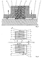
- FIG. 1 a half-sided longitudinal section is designed according to the invention Stock depicted.
- any propeller drive (not shown here) used two counter-driven shafts to increase the efficiency.
- One propeller is with the inner shaft 1, in most cases as a solid shaft formed, and the other propeller driven with a hollow shaft 2, the Hollow shaft 2 concentrically includes the inner shaft 1.
- the Hollow shaft 2 two flanges 3, 4, which are arranged at a distance from each other.
- the cavity between the two flanges 3, 4 is according to the invention trained camp arranged. It consists of an inner rotor 5 and one External runners 6, which are toothed together like a comb via supporting webs. details this can be seen in FIG. 2.
- an intermediate ring 7 is arranged over several Dowel screws 8, not shown, with the external rotor 6 or with the two Flanges 3, 4 is connected.
- FIG 2 are the details of the bearing designed according to the invention shown.
- Both the inner rotor 5 and the outer rotor 6 extend axially concentric supporting webs 9, 9 ', 9 "or 10, 10', 10", the comb-like are interlinked.
- the end areas of the supporting webs 9 - 9 "or 10 - 10" point a distance 11 from the respective inner wall of the inner rotor 5 or outer rotor 6 or 12 on.
- the sliding surfaces 13 and 14 are for clarification with a black Dot marked. Thanks to precision and elastic resilience of the supporting bars 9 - 9 "or 10 - 10" ensures that all sliding surfaces 13 and 14 are even wear so that a multi-surface principle is established and in this way the Surface pressure is reduced.
- FIG. 3 shows the details of the lubrication system in the embodiment according to the invention Camp.
- the lubricant is supplied or discharged 21 axially through in each case Bores 22, 22 ', 23, 23' arranged radially in the hollow shaft 2.
- These holes 22, 22 ', 23, 23' open into an annular space 24, 25 which is formed by the Inner shaft 1 and the hollow shaft 2 arranged radially at a distance from it Sealing of the respective annular space 24, 25 to the right or to the left takes place via a shaft seal 26, 27.
- For the distribution in the radial direction are on the one hand
- Outer rotor 6 radially extending channels 28, 28 'and radially in the inner rotor 5 extending channels 29, 29 'arranged.
- main channels 28, 28 'and 29, 29' extend axially branches 30, 30 ', 31, 31', 32, 32 ', 33, 33'.
- These cross channels 30 - 33 ' open in the annular spaces 34, 35 between the end face of the respective Support web 9 - 9 'or 10 - 10' 'and the respective inner wall of the inner rotor 5 or External rotor 6.
- the lubricant distribution described above guarantees a 360 ° lubrication, which is crucial for counter-rotating shafts 1, 2 Significance for the hydrostatic or hydrodynamic separation of the sliding surfaces 13, 14 is.
Landscapes
- Engineering & Computer Science (AREA)
- General Engineering & Computer Science (AREA)
- Mechanical Engineering (AREA)
- Chemical & Material Sciences (AREA)
- Combustion & Propulsion (AREA)
- Ocean & Marine Engineering (AREA)
- Sliding-Contact Bearings (AREA)
- Support Of The Bearing (AREA)
- Magnetic Bearings And Hydrostatic Bearings (AREA)
Applications Claiming Priority (2)
| Application Number | Priority Date | Filing Date | Title |
|---|---|---|---|
| DE19623278 | 1996-05-31 | ||
| DE19623278A DE19623278C2 (de) | 1996-05-31 | 1996-05-31 | Lagerung für zwei gegenläufig angetriebene Wellen |
Publications (3)
| Publication Number | Publication Date |
|---|---|
| EP0810152A2 EP0810152A2 (de) | 1997-12-03 |
| EP0810152A3 EP0810152A3 (de) | 1999-05-26 |
| EP0810152B1 true EP0810152B1 (de) | 2001-02-28 |
Family
ID=7796639
Family Applications (1)
| Application Number | Title | Priority Date | Filing Date |
|---|---|---|---|
| EP97250165A Expired - Lifetime EP0810152B1 (de) | 1996-05-31 | 1997-05-27 | Lagerung für zwei gegenläufig angetriebene Wellen |
Country Status (4)
| Country | Link |
|---|---|
| EP (1) | EP0810152B1 (da) |
| DE (2) | DE19623278C2 (da) |
| DK (1) | DK0810152T3 (da) |
| ES (1) | ES2155962T3 (da) |
Families Citing this family (4)
| Publication number | Priority date | Publication date | Assignee | Title |
|---|---|---|---|---|
| FR2773586B1 (fr) * | 1998-01-09 | 2000-02-11 | Snecma | Turbomachine a freinage mutuel d'arbres concentriques |
| WO2009049070A2 (en) * | 2007-10-09 | 2009-04-16 | Smartin Technologies, Llc | Compact non-contact mechanical coupling, damping and/or load bearing device |
| DE102011121562A1 (de) * | 2011-12-20 | 2013-06-20 | Robert Bosch Gmbh | Gleitlager |
| CN115030952B (zh) * | 2022-06-06 | 2024-06-21 | 中国船舶重工集团公司第七一九研究所 | 推力轴承及轮缘推进器 |
Family Cites Families (5)
| Publication number | Priority date | Publication date | Assignee | Title |
|---|---|---|---|---|
| US3527545A (en) * | 1969-04-14 | 1970-09-08 | Algoship Int | Contrarotating propeller drive |
| US5281033A (en) * | 1990-10-09 | 1994-01-25 | Ide Russell D | Housed bearing assembly with sealed roller |
| JP3122198B2 (ja) * | 1991-10-15 | 2001-01-09 | 三菱重工業株式会社 | 二重反転式プロペラ装置における内軸用すべり軸受 |
| US5275493A (en) * | 1992-04-23 | 1994-01-04 | Ide Russell D | Plain bearing with multiple load bearing surfaces |
| DE4308778A1 (de) * | 1993-03-19 | 1994-09-22 | Renk Tacke Gmbh | Schiffsantrieb mit konterrotierenden koaxialen Propellerwellen |
-
1996
- 1996-05-31 DE DE19623278A patent/DE19623278C2/de not_active Expired - Fee Related
-
1997
- 1997-05-27 EP EP97250165A patent/EP0810152B1/de not_active Expired - Lifetime
- 1997-05-27 ES ES97250165T patent/ES2155962T3/es not_active Expired - Lifetime
- 1997-05-27 DK DK97250165T patent/DK0810152T3/da active
- 1997-05-27 DE DE59703029T patent/DE59703029D1/de not_active Expired - Fee Related
Also Published As
| Publication number | Publication date |
|---|---|
| DE19623278C2 (de) | 2002-01-03 |
| EP0810152A2 (de) | 1997-12-03 |
| DK0810152T3 (da) | 2001-05-21 |
| ES2155962T3 (es) | 2001-06-01 |
| EP0810152A3 (de) | 1999-05-26 |
| DE59703029D1 (de) | 2001-04-05 |
| DE19623278A1 (de) | 1997-12-04 |
Similar Documents
| Publication | Publication Date | Title |
|---|---|---|
| DE69203908T2 (de) | Traglagereinheit. | |
| DE2416640A1 (de) | Lageranordnung zum lagern einer sich drehenden welle in einer stationaeren lagerhalterung | |
| DE3619728A1 (de) | Homokinetisches universalgelenk | |
| EP3057822B1 (de) | Wälzlager | |
| DE69529422T2 (de) | Umkehrbare lagervorrichtung für umkehrbare doppelschraube | |
| DE2647588A1 (de) | Grosswaelzlager in segmentbauweise | |
| DE2857672C2 (de) | Kippsegment-Radiallager für hochbelastete, schnellaufende Wellen | |
| DE19826460C2 (de) | Lageranordnung | |
| DE3603604A1 (de) | Lager fuer rotationsmaschinen | |
| DE19621585B4 (de) | Anordnung beim Antrieb einer Breitstreckwalze | |
| EP0810152B1 (de) | Lagerung für zwei gegenläufig angetriebene Wellen | |
| EP0222692A2 (de) | Wälzlager | |
| DE60126405T2 (de) | Schiffsantriebssystem | |
| DE2210979C3 (de) | Spiralrillengleitlager | |
| EP1015779B1 (de) | Pendelrollenlager | |
| DE4216408A1 (de) | Gleitlager | |
| DE3444000C2 (da) | ||
| DE2311864A1 (de) | Laengslagervorrichtung mit konischem reibring | |
| DE3305768C2 (da) | ||
| EP3271596A1 (de) | Hydrodynamisches gleitlager | |
| EP3788267A1 (de) | Wälzlager | |
| EP4430327A1 (de) | Anordnung mit zwei bauteilen und einem ölübertragungsring | |
| DE2542947C3 (de) | Als Hohlring ausgebildeter Festschmierring zur Versorgung eines Gleitlagers mit Schmiermittel | |
| DE1077924B (de) | Elastische, aus Leichtmetall bestehende Lagerbuechse fuer Gleitlager | |
| DE3104261A1 (de) | Lagerung fuer die verdrehbaren rotorblaetter eines hubschraubers |
Legal Events
| Date | Code | Title | Description |
|---|---|---|---|
| PUAI | Public reference made under article 153(3) epc to a published international application that has entered the european phase |
Free format text: ORIGINAL CODE: 0009012 |
|
| AK | Designated contracting states |
Kind code of ref document: A2 Designated state(s): DE DK ES FI FR GB IT |
|
| RAP1 | Party data changed (applicant data changed or rights of an application transferred) |
Owner name: A. FRIEDR. FLENDER AG |
|
| PUAL | Search report despatched |
Free format text: ORIGINAL CODE: 0009013 |
|
| AK | Designated contracting states |
Kind code of ref document: A3 Designated state(s): DE DK ES FI FR GB IT |
|
| 17P | Request for examination filed |
Effective date: 19990528 |
|
| GRAG | Despatch of communication of intention to grant |
Free format text: ORIGINAL CODE: EPIDOS AGRA |
|
| GRAG | Despatch of communication of intention to grant |
Free format text: ORIGINAL CODE: EPIDOS AGRA |
|
| GRAH | Despatch of communication of intention to grant a patent |
Free format text: ORIGINAL CODE: EPIDOS IGRA |
|
| 17Q | First examination report despatched |
Effective date: 20000817 |
|
| GRAH | Despatch of communication of intention to grant a patent |
Free format text: ORIGINAL CODE: EPIDOS IGRA |
|
| GRAA | (expected) grant |
Free format text: ORIGINAL CODE: 0009210 |
|
| AK | Designated contracting states |
Kind code of ref document: B1 Designated state(s): DE DK ES FI FR GB IT |
|
| REF | Corresponds to: |
Ref document number: 59703029 Country of ref document: DE Date of ref document: 20010405 |
|
| ET | Fr: translation filed | ||
| GBT | Gb: translation of ep patent filed (gb section 77(6)(a)/1977) |
Effective date: 20010327 |
|
| ITF | It: translation for a ep patent filed | ||
| REG | Reference to a national code |
Ref country code: DK Ref legal event code: T3 |
|
| REG | Reference to a national code |
Ref country code: ES Ref legal event code: FG2A Ref document number: 2155962 Country of ref document: ES Kind code of ref document: T3 |
|
| REG | Reference to a national code |
Ref country code: GB Ref legal event code: IF02 |
|
| PLBE | No opposition filed within time limit |
Free format text: ORIGINAL CODE: 0009261 |
|
| STAA | Information on the status of an ep patent application or granted ep patent |
Free format text: STATUS: NO OPPOSITION FILED WITHIN TIME LIMIT |
|
| 26N | No opposition filed | ||
| PGFP | Annual fee paid to national office [announced via postgrant information from national office to epo] |
Ref country code: GB Payment date: 20030516 Year of fee payment: 7 |
|
| PGFP | Annual fee paid to national office [announced via postgrant information from national office to epo] |
Ref country code: FR Payment date: 20030521 Year of fee payment: 7 Ref country code: FI Payment date: 20030521 Year of fee payment: 7 |
|
| PGFP | Annual fee paid to national office [announced via postgrant information from national office to epo] |
Ref country code: DK Payment date: 20030522 Year of fee payment: 7 |
|
| PGFP | Annual fee paid to national office [announced via postgrant information from national office to epo] |
Ref country code: ES Payment date: 20030523 Year of fee payment: 7 |
|
| PGFP | Annual fee paid to national office [announced via postgrant information from national office to epo] |
Ref country code: DE Payment date: 20030527 Year of fee payment: 7 |
|
| PG25 | Lapsed in a contracting state [announced via postgrant information from national office to epo] |
Ref country code: GB Free format text: LAPSE BECAUSE OF NON-PAYMENT OF DUE FEES Effective date: 20040527 Ref country code: FI Free format text: LAPSE BECAUSE OF NON-PAYMENT OF DUE FEES Effective date: 20040527 |
|
| PG25 | Lapsed in a contracting state [announced via postgrant information from national office to epo] |
Ref country code: ES Free format text: LAPSE BECAUSE OF NON-PAYMENT OF DUE FEES Effective date: 20040528 |
|
| PG25 | Lapsed in a contracting state [announced via postgrant information from national office to epo] |
Ref country code: DK Free format text: LAPSE BECAUSE OF NON-PAYMENT OF DUE FEES Effective date: 20040601 |
|
| PG25 | Lapsed in a contracting state [announced via postgrant information from national office to epo] |
Ref country code: DE Free format text: LAPSE BECAUSE OF NON-PAYMENT OF DUE FEES Effective date: 20041201 |
|
| REG | Reference to a national code |
Ref country code: DK Ref legal event code: EBP |
|
| GBPC | Gb: european patent ceased through non-payment of renewal fee | ||
| PG25 | Lapsed in a contracting state [announced via postgrant information from national office to epo] |
Ref country code: FR Free format text: LAPSE BECAUSE OF NON-PAYMENT OF DUE FEES Effective date: 20050131 |
|
| REG | Reference to a national code |
Ref country code: FR Ref legal event code: ST |
|
| PG25 | Lapsed in a contracting state [announced via postgrant information from national office to epo] |
Ref country code: IT Free format text: LAPSE BECAUSE OF NON-PAYMENT OF DUE FEES Effective date: 20050527 |
|
| REG | Reference to a national code |
Ref country code: ES Ref legal event code: FD2A Effective date: 20040528 |