EP0809977A2 - Dispenser for marker disks - Google Patents
Dispenser for marker disks Download PDFInfo
- Publication number
- EP0809977A2 EP0809977A2 EP97104174A EP97104174A EP0809977A2 EP 0809977 A2 EP0809977 A2 EP 0809977A2 EP 97104174 A EP97104174 A EP 97104174A EP 97104174 A EP97104174 A EP 97104174A EP 0809977 A2 EP0809977 A2 EP 0809977A2
- Authority
- EP
- European Patent Office
- Prior art keywords
- marking
- insert
- opening
- cover
- lid
- Prior art date
- Legal status (The legal status is an assumption and is not a legal conclusion. Google has not performed a legal analysis and makes no representation as to the accuracy of the status listed.)
- Withdrawn
Links
Images


Classifications
-
- B—PERFORMING OPERATIONS; TRANSPORTING
- B65—CONVEYING; PACKING; STORING; HANDLING THIN OR FILAMENTARY MATERIAL
- B65D—CONTAINERS FOR STORAGE OR TRANSPORT OF ARTICLES OR MATERIALS, e.g. BAGS, BARRELS, BOTTLES, BOXES, CANS, CARTONS, CRATES, DRUMS, JARS, TANKS, HOPPERS, FORWARDING CONTAINERS; ACCESSORIES, CLOSURES, OR FITTINGS THEREFOR; PACKAGING ELEMENTS; PACKAGES
- B65D83/00—Containers or packages with special means for dispensing contents
- B65D83/04—Containers or packages with special means for dispensing contents for dispensing annular, disc-shaped, spherical or like small articles, e.g. tablets or pills
- B65D83/0409—Containers or packages with special means for dispensing contents for dispensing annular, disc-shaped, spherical or like small articles, e.g. tablets or pills the dispensing means being adapted for delivering one article, or a single dose, upon each actuation
-
- A—HUMAN NECESSITIES
- A61—MEDICAL OR VETERINARY SCIENCE; HYGIENE
- A61C—DENTISTRY; APPARATUS OR METHODS FOR ORAL OR DENTAL HYGIENE
- A61C5/00—Filling or capping teeth
- A61C5/40—Implements for surgical treatment of the roots or nerves of the teeth; Nerve needles; Methods or instruments for medication of the roots
- A61C5/44—Means for controlling working depth, e.g. supports or boxes with depth-gauging means, stop positioners or files with adjustably-mounted handles
-
- B—PERFORMING OPERATIONS; TRANSPORTING
- B65—CONVEYING; PACKING; STORING; HANDLING THIN OR FILAMENTARY MATERIAL
- B65D—CONTAINERS FOR STORAGE OR TRANSPORT OF ARTICLES OR MATERIALS, e.g. BAGS, BARRELS, BOTTLES, BOXES, CANS, CARTONS, CRATES, DRUMS, JARS, TANKS, HOPPERS, FORWARDING CONTAINERS; ACCESSORIES, CLOSURES, OR FITTINGS THEREFOR; PACKAGING ELEMENTS; PACKAGES
- B65D2583/00—Containers or packages with special means for dispensing contents
- B65D2583/04—For dispensing annular, disc-shaped or spherical or like small articles or tablets
- B65D2583/0445—For dispensing annular, disc-shaped or spherical or like small articles or tablets characterised by the shape of the container
- B65D2583/0468—For dispensing annular, disc-shaped or spherical or like small articles or tablets characterised by the shape of the container of drawer-and-shell type
Definitions
- the invention relates to a dispenser for marking discs for limiting the depth of penetration of tooth root canal preparation instruments or the like, with a box-like structure comprising a base and a cover, the space between the base and the cover at least partially having a height which is approximately equal to the thickness of the marking discs, and a guide for separating the marking disks and for arranging a marking disk at a specific location is provided, at which location an insertion opening in the bottom and an opening in the lid are provided, the opening in the lid being so large that a marking disk passes through.
- Such a dispenser is known from DE 34 19 712 C2.
- marking disks for example made of silicone or rubber, are used as stoppers to indicate this depth on the tooth root canal preparation instrument.
- a marking disc is placed on the tooth root canal preparation instrument before use, to the point where the tooth root canal preparation instrument is allowed to penetrate into the tooth canal.
- the dispenser of the type mentioned at the outset is intended to facilitate the mounting of the marking disks by ensuring that a marking disk is arranged at a specific point in such a way that it can be impaled by the tooth root canal preparation instrument and together with the tooth root canal preparation instrument at the point indicating the depth of penetration into the tooth root can be removed from the donor.
- a dispenser is provided in the known dispenser, which closes the opening in the cover in the non-actuated state, so that no marking discs can fall out, and in the actuated state opens the opening in the lid and at the same time ensures that a marking disc is placed under the opening in the lid.
- Such an allocator represents an additional component which is relatively complicated in its shape and complicates the structure of the dispenser.
- the object on which the invention is based is therefore to design the dispenser of the type mentioned at the outset in such a way that it has a simple structure and is inexpensive to produce.
- the dispenser according to the invention has no complex mechanical separating devices and no moving components and is easy to refill by merely using the bottom and lid of the box-like structure, e.g. can be separated from one another by pulling off an adhesive strip holding these components together.
- the box-like structure and the insert can be made of the same material, so that the dispenser can be disposed of or recycled according to type.
- the production of the dispenser according to the invention is very inexpensive.
- the dispenser for marking disks 4 shown in FIGS. 1 and 2 for limiting the penetration depth of tooth root canal preparation instruments essentially comprises a base 1, a cover 2, an insert 3 arranged in the base 1 and an insert cover 5 into which the box-like structure from the base 1 , the lid 2 and the insert 3 is inserted, as shown in particular in Fig. 2.
- the insert 3 is designed so that its depth, i.e. the space between its bottom surface and the cover 2 at least at one point 9 essentially corresponds to the thickness of the marking disk 4.
- the remaining space between the insert 3 and the lid 2 can be made deeper.
- a guide in the form of a web 8 is provided, which runs approximately at a distance from the width of a marking disc 4 parallel to an edge of the insert 3 and ensures that the marking discs 4 are separated and each a marking disc 4 is arranged at a specific point in the insert 3, which in the exemplary embodiment shown in FIG. 1 is the front end of the channel, which is delimited between the web 8 and the edge of the insert 3.
- an insertion opening 7 is provided in the insert 3, which is so large that a tooth root canal preparation instrument can pass through it.
- a corresponding opening is in the bottom 1.
- an opening 6 is provided in the cover 2 at this point, the size of which corresponds at least to the size of a marking disk 4.
- the insert 3 can consist of a deep-drawn plastic film, or can be formed from a milled plastic film material.
- the insert sleeve 5 must be designed so that it covers the opening 6 in the lid 2 when the box-like structure of bottom 1, lid 2 and insert 3 is pushed in, so that no marking disks can fall out.
- the insert cover has a rectangular cutout 10, which is arranged asymmetrically with respect to the longitudinal axis, so that it is delimited by edges of different widths. The wider edge covers the opening 6 in the cover 2 when the box-like structure of cover 2, base 1 and insert 3 is pushed in.
- a marking disc 4 is removed from the dispenser with the structure described above in the manner which is shown in FIGS. 2 and 3 in detail. This means that when a marking disc 4 is to be removed, the box-like structure from the base 1 and the lid 2 with the insert 3 therein is pushed out at least as far from the insert sleeve 5 or the insert sleeve 5 is pushed back so far that the Opening 6 in cover 2 is released. Due to the design of the bottom surface of the insert 3 and the web 8, it is ensured that there is always only one marking disc 4 under this opening 6.
- a tooth root canal preparation instrument 11 is then inserted through the opening 6, the marking disc 4 underneath, the puncture opening 7 in the insert 3 and the opening in the bottom 1 below, until the marking disc 4 is pulled up to the point that corresponds to the permissible depth of penetration into the tooth root.
- the tooth root canal preparation instrument 11 is then taken out with the opened marking disc 4 through the opening 6 in the cover part 2 and is then ready for use.
- the insert sleeve 5 can also be made from a plastic material, for example a plastic film, this results in a structure which is relatively simple and involves low production costs. Nevertheless, it is ensured that the marking discs can be removed individually without problems and that the dispenser is securely closed when not in use.
Landscapes
- Health & Medical Sciences (AREA)
- Engineering & Computer Science (AREA)
- Biomedical Technology (AREA)
- Neurology (AREA)
- Neurosurgery (AREA)
- Nuclear Medicine, Radiotherapy & Molecular Imaging (AREA)
- Surgery (AREA)
- Oral & Maxillofacial Surgery (AREA)
- Dentistry (AREA)
- Epidemiology (AREA)
- Life Sciences & Earth Sciences (AREA)
- Animal Behavior & Ethology (AREA)
- General Health & Medical Sciences (AREA)
- Public Health (AREA)
- Veterinary Medicine (AREA)
- Mechanical Engineering (AREA)
- Dental Tools And Instruments Or Auxiliary Dental Instruments (AREA)
Abstract
Spender für Markierungsscheiben zum Begrenzen der Eindringtiefe von Zahnwurzelkanalaufbereitungsinstrumenten oder dergleichen. Der Spender besteht aus einem schachtelartigen Aufbau aus einem Boden 1 und einem Deckel 2. Der Raum zwischen dem Boden 1 und dem Deckel 2 hat wenigstens teilweise eine Höhe, die etwa gleich der Dicke der Markierungsscheiben ist. Es ist eine Führung 8 zum Vereinzeln der Markierungsscheiben und zum Anordnen einer Markierungsscheibe an einer bestimmten Stelle vorgesehen. An dieser Stelle befinden sich eine Einstichöffnung 7 im Boden 1 und eine Öffnung 6 im Deckel 2. Die Öffnung 6 im Deckel 2 ist wenigstens so groß, daß eine Markierungsscheibe 4 hindurchgeht. Der schachtelartige Aufbau aus dem Boden 1 und dem Deckel 2 ist in einer Einschubhülle 5 angeordnet, die so ausgebildet ist, daß sie im eingeschobenen Zustand des schachtelartigen Aufbaus die Öffnung 6 im Deckel 2 abdeckt.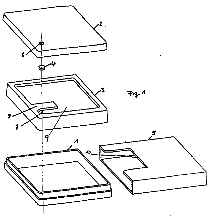
Description
Die Erfindung betrifft einen Spender für Markierungsscheiben zum Begrenzen der Eindringtiefe von Zahnwurzelkanalaufbereitungsinstrumenten oder dergleichen mit einem schachtelartigen Aufbau aus einem Boden und einem Deckel, wobei der Raum zwischen dem Boden und dem Deckel wenigstens teilweise eine Höhe hat, die etwa gleich der Dicke der Markierungsscheiben ist, und eine Führung zum Vereinzeln der Markierungsscheiben und zum Anordnen einer Markierungsscheibe an einer bestimmten Stelle vorgesehen ist, an welcher Stelle eine Einstichöffnung im Boden und eine Öffnung im Deckel vorgesehen sind, welche Öffnung im Deckel so groß ist, daß eine Markierungsscheibe hindurchgeht.The invention relates to a dispenser for marking discs for limiting the depth of penetration of tooth root canal preparation instruments or the like, with a box-like structure comprising a base and a cover, the space between the base and the cover at least partially having a height which is approximately equal to the thickness of the marking discs, and a guide for separating the marking disks and for arranging a marking disk at a specific location is provided, at which location an insertion opening in the bottom and an opening in the lid are provided, the opening in the lid being so large that a marking disk passes through.
Ein derartiger Spender ist aus der DE 34 19 712 C2 bekannt.Such a dispenser is known from DE 34 19 712 C2.
Da Zahnwurzelkanalaufbereitungsinstrumente nur bis zu einer gewissen Tiefe in die Zahnwurzel eindringen dürfen, werden Markierungsscheiben, beispielsweise aus Silikon oder Gummi, als Stopper dazu benutzt, diese Tiefe am Zahnwurzelkanalaufbereitungsinstrument anzuzeigen. Zu diesem Zweck wird vor dem Einsatz eine Markierungsscheibe auf das Zahnwurzelkanalaufbereitungsinstrument aufgezogen, und zwar bis zu einer Stelle, bis zu der das Zahnwurzelkanalaufbereitungsinstrument in den Zahnkanal eindringen darf.Since tooth root canal preparation instruments are only allowed to penetrate into the tooth root to a certain depth, marking disks, for example made of silicone or rubber, are used as stoppers to indicate this depth on the tooth root canal preparation instrument. For this purpose, a marking disc is placed on the tooth root canal preparation instrument before use, to the point where the tooth root canal preparation instrument is allowed to penetrate into the tooth canal.
Der Spender der eingangs genannten Art soll das Aufziehen der Markierungsscheiben erleichtern, indem dafür gesorgt wird, daß eine Markierungsscheibe an einer bestimmten Stelle so angeordnet ist, daß sie vom Zahnwurzelkanalaufbereitungsinstrument aufgespießt werden kann und zusammen mit dem Zahnwurzelkanalaufbereitungsinstrument an der die Eindringtiefe in die Zahnwurzel anzeigenden Stelle aus dem Spender entnommen werden kann.The dispenser of the type mentioned at the outset is intended to facilitate the mounting of the marking disks by ensuring that a marking disk is arranged at a specific point in such a way that it can be impaled by the tooth root canal preparation instrument and together with the tooth root canal preparation instrument at the point indicating the depth of penetration into the tooth root can be removed from the donor.
Zur Vereinzelung und Anordnung einer Markierungsscheibe an der Stelle, an der sie aufgespießt und entnommen werden kann, ist bei dem bekannten Spender ein Zuteiler vorgesehen, der im nicht betätigten Zustand die Öffnung im Deckel verschließt, so daß keine Markierungsscheiben herausfallen können, und im betätigten Zustand die Öffnung im Deckel freigibt und gleichzeitig dafür sorgt, daß eine Markierungsscheibe unter der Öffnung im Deckel angeordnet wird.For the separation and arrangement of a marking disc at the point at which it can be impaled and removed, a dispenser is provided in the known dispenser, which closes the opening in the cover in the non-actuated state, so that no marking discs can fall out, and in the actuated state opens the opening in the lid and at the same time ensures that a marking disc is placed under the opening in the lid.
Ein derartiger Zuteiler stellt ein zusätzliches in seiner Formgebung relativ kompliziertes Bauteil dar, das den Aufbau des Spenders kompliziert.Such an allocator represents an additional component which is relatively complicated in its shape and complicates the structure of the dispenser.
Die der Erfindung zugrundeliegende Aufgabe besteht daher darin, den Spender der eingangs genannten Art so auszubilden, daß er einen einfachen Aufbau hat und in seiner Herstellung mit geringen Kosten verbunden ist.The object on which the invention is based is therefore to design the dispenser of the type mentioned at the outset in such a way that it has a simple structure and is inexpensive to produce.
Diese Aufgabe wird gemäß der Erfindung durch eine Einschubhülle gelöst, in die der schachtelartige Aufbau eingeschoben ist und die so ausgebildet ist, daß sie im eingeschobenen Zustand die Öffnung im Deckel abdeckt.This object is achieved according to the invention by means of an insert sleeve into which the box-like structure is inserted and which is designed such that it covers the opening in the lid when inserted.
Bei der erfindungsgemäßen Ausbildung ist somit kein Zuteiler vorgesehen, sondern wird die Funktion der Abdeckung der Entnahmeöffnung im Deckel von einer einfachen Einschubhülle erfüllt, in die der schachtelartige Aufbau des Spenders im Zustand der Nichtbenutzung eingeschoben ist. Wenn eine Markierungsscheibe dem Spender entnommen werden soll, muß lediglich die Einschubhülle soweit zurückgeschoben werden, daß die Öffnung im Deckel freiliegt, die Entnahme der darunterliegenden Markierungsscheibe ist dann mittels eines Zahnwurzelkanalaufbereitungsinstrumentes problemlos dadurch möglich, daß mit dem Zahnwurzelkanalaufbereitungsinstrument durch die Öffnung im Deckel die Markierungsscheibe durchstoßen wird, wobei das Zahnwurzelkanalaufbereitungsinstrument durch die Einstichöffnung im Boden hindurchgehen kann.In the embodiment according to the invention, therefore, no allocator is provided, but the function of covering the removal opening in the lid is fulfilled by a simple insert sleeve into which the box-like structure of the dispenser is inserted when not in use. If a marking disc is to be removed from the dispenser, all that has to be done is to push the insert sleeve back so far that the opening in the cover is exposed; the removal of the marking disc underneath is then easily possible by means of a tooth root canal preparation instrument by piercing the marking disc with the tooth root canal preparation instrument through the opening in the cover the tooth root canal preparation instrument can pass through the puncture opening in the floor.
Weitere Vorteile des erfindungsgemäßen Spenders sind darin zu sehen, daß er keine aufwendigen mechanischen Vereinzelungseinrichtungen und keine beweglichen Bauteile aufweist und leicht wiederbefüllbar ist, indem lediglich Boden und Deckel des schachtelartigen Aufbaus z.B. durch Abziehen eines diese Bauteile zusammenhaltenden Klebestreifens voneinander getrennt werden.Further advantages of the dispenser according to the invention can be seen in the fact that it has no complex mechanical separating devices and no moving components and is easy to refill by merely using the bottom and lid of the box-like structure, e.g. can be separated from one another by pulling off an adhesive strip holding these components together.
Besonders bevorzugte Ausgestaltungen und Weiterbildungen des erfindungsgemäßen Spenders sind Gegenstand der Ansprüche 2 bis 6.Particularly preferred refinements and developments of the dispenser according to the invention are the subject of
Der schachtelartige Aufbau und der Einsatz können aus dem gleichen Material gefertigt sein, so daß der Spender sortenrein zu entsorgen bzw. wiederzuverwerten ist. Die Herstellung des erfindungsgemäßen Spenders ist sehr kostenkünstig.The box-like structure and the insert can be made of the same material, so that the dispenser can be disposed of or recycled according to type. The production of the dispenser according to the invention is very inexpensive.
Im folgenden wird anhand der zugehörigen Zeichnung ein besonders bevorzugtes Ausführungsbeispiel der Erfindung näher beschrieben. Es zeigen
- Fig. 1 eine auseinandergezogene perspektivische Ansicht der einzelnen Bauteile des Ausführungsbeispiels,
- Fig. 2 eine perspektivische Ansicht des Ausführungsbeispiels im zusammengesetzten Zustand bei der Entnahme einer Markierungsscheibe und
- Fig. 3 in einer Teilschnittansicht des Entnahmebereiches des Ausführungsbeispiels, wie eine Markierungsscheibe mittels eines Zahnwurzelkanalaufbereitungsinstrumentes entnommen wird.
- 1 is an exploded perspective view of the individual components of the embodiment,
- Fig. 2 is a perspective view of the embodiment in the assembled state when removing a marker disc and
- 3 shows a partial sectional view of the removal area of the exemplary embodiment of how a marking disk is removed by means of a tooth root canal preparation instrument.
Der in Fig. 1 und 2 dargestellte Spender für Markierungsscheiben 4 zum Begrenzen der Eindringtiefe von Zahnwurzelkanalaufbereitungsinstrumenten umfaßt im wesentlichen einen Boden 1, einen Deckel 2, einen im Boden 1 angeordneten Einsatz 3 sowie eine Einschubhülle 5, in die der schachtelartige Aufbau aus dem Boden 1, dem Deckel 2 und dem Einsatz 3 eingeschoben wird, wie es insbesondere in Fig. 2 dargestellt ist.The dispenser for marking
Der Einsatz 3 ist so ausgebildet, daß seine Tiefe, d.h. der Zwischenraum zwischen seiner Bodenfläche und dem Deckel 2 an wenigstens einer Stelle 9 im wesentlichen der Dicke der Markierungsscheibe 4 entspricht. Der übrige Raum zwischen dem Einsatz 3 und dem Deckel 2 kann tiefer ausgebildet sein. Wie es in Fig. 1 dargestellt ist, ist eine Führung in Form eines Stegs 8 vorgesehen, der etwa im Abstand der Breite einer Markierungsscheibe 4 parallel zu einem Rand des Einsatzes 3 verläuft und dafür sorgt, daß die Markierungsscheiben 4 vereinzelt werden und jeweils eine Markierungsscheibe 4 an einer bestimmten Stelle im Einsatz 3 angeordnet wird, die bei dem in Fig. 1 dargestellten Ausführungsbeispiel das vordere Ende des Kanals ist, der zwischen dem Steg 8 und dem Rand des Einsatzes 3 begrenzt ist.The
An dieser Stelle, an der eine einzelne Markierungsscheibe 4 angeordnet wird, ist im Einsatz 3 eine Einstichöffnung 7 vorgesehen, die so groß ist, daR ein Zahnwurzelkanalaufbereitungsinstrument hindurchgehen kann. Eine entsprechende Öffnung befindet sich im Boden 1. Im Deckel 2 ist an dieser Stelle eine Öffnung 6 vorgesehen, deren Größe wenigstens der Größe einer Markierungsscheibe 4 entspricht.At this point, at which a
Der Einsatz 3 kann aus einer tiefgezogenen Kunststoffolie bestehen, oder aus ausgefrästem Kunststoffolienmaterial gebildet sein.The
Die Einschubhülle 5 muß so ausgebildet sein, daß sie im eingeschobenen Zustand des schachtelartigen Aufbaus aus Boden 1, Deckel 2 und Einsatz 3 die Öffnung 6 im Deckel 2 abdeckt, damit keine Markierungsscheiben herausfallen können. Bei dem in Fig. 1 dargestellten Ausführungsbeispiel weist die Einschubhülle einen rechtwinkligen Ausschnitt 10 auf, der bezüglich der Längsachse asymmetrisch angeordnet ist, so daß er von Rändern unterschiedlicher Breite begrenzt wird. Der breitere Rand deckt im eingeschobenen Zustand des schachtelartigen Aufbaus aus Deckel 2, Boden 1 und Einsatz 3 die Öffnung 6 im Deckel 2 ab.The
Eine Markierungsscheibe 4 wird aus dem Spender mit dem oben beschriebenen Aufbau in der Weise entnommen, die in den Fig. 2 und 3 im einzelnen dargestellt ist. Das heißt, daß dann, wenn eine Markierungsscheibe 4 entnommen werden soll, der schachtelartige Aufbau aus dem Boden 1 und dem Deckel 2 mit dem darin befindlichen Einsatz 3 wenigstens soweit aus der Einschubhülle 5 herausgeschoben wird bzw. die Einschubhülle 5 soweit zurückgeschoben wird, daß die Öffnung 6 im Deckel 2 freikommt. Aufgrund der Ausbildung der Bodenfläche des Einsatzes 3 und des Stegs 8 ist dafür gesorgt, daß sich unter dieser Öffnung 6 immer nur eine Markierungsscheibe 4 befindet. In diesem Zustand wird dann mit einem Zahnwurzelkanalaufbereitungsinstrument 11 durch die Öffnung 6, die darunter liegende Markierungsscheibe 4 sowie die Einstichöffnung 7 im Einsatz 3 und die darunter liegende Öffnung im Boden 1 eingestochen und zwar soweit, bis die Markierungsscheibe 4 zu der Stelle aufgezogen ist, die der zulässigen Eindringtiefe in die Zahnwurzel entspricht. Das Zahnwurzelkanalaufbereitungsinstrument 11 wird dann mit der aufgezogenen Markierungsscheibe 4 durch die Öffnung 6 im Deckelteil 2 herausgenommen und ist dann einsatzbereit.A
Da neben dem Boden 1, dem Deckel 2 und dem Einsatz 3 auch die Einschubhülle 5 aus einem Kunststoffmaterial, beispielsweise einer Kunststoffolie, gefertigt werden kann, ergibt sich ein Aufbau, der relativ einfach und bei der Herstellung mit geringen Kosten verbunden ist. Dennoch ist sichergestellt, daß die Markierungsscheiben einzeln problemlos entnommen werden können und der Spender im Zustand der Nichtbenutzung sicher verschlossen ist.Since, in addition to the base 1, the
Claims (6)
Applications Claiming Priority (2)
| Application Number | Priority Date | Filing Date | Title |
|---|---|---|---|
| DE19622033A DE19622033C1 (en) | 1996-05-31 | 1996-05-31 | Distributor for marking discs for limiting penetration depth of tooth root channel preparation instruments |
| DE19622033 | 1996-05-31 |
Publications (2)
| Publication Number | Publication Date |
|---|---|
| EP0809977A2 true EP0809977A2 (en) | 1997-12-03 |
| EP0809977A3 EP0809977A3 (en) | 1999-01-20 |
Family
ID=7795887
Family Applications (1)
| Application Number | Title | Priority Date | Filing Date |
|---|---|---|---|
| EP97104174A Withdrawn EP0809977A3 (en) | 1996-05-31 | 1997-03-12 | Dispenser for marker disks |
Country Status (3)
| Country | Link |
|---|---|
| US (1) | US5827060A (en) |
| EP (1) | EP0809977A3 (en) |
| DE (1) | DE19622033C1 (en) |
Families Citing this family (11)
| Publication number | Priority date | Publication date | Assignee | Title |
|---|---|---|---|---|
| US6358049B1 (en) | 2000-02-08 | 2002-03-19 | Leon A. Cerniway | Endodontic tool length gauge |
| US7303817B2 (en) | 2001-10-24 | 2007-12-04 | Weitao Jia | Dental filling material |
| US7211136B2 (en) | 2001-10-24 | 2007-05-01 | Pentron Clinical Technologies, Llc | Dental filling material |
| US7750063B2 (en) | 2001-10-24 | 2010-07-06 | Pentron Clinical Technologies, Llc | Dental filling material |
| US7204875B2 (en) | 2001-10-24 | 2007-04-17 | Pentron Clinical Technologies, Llc | Dental filling material |
| US7204874B2 (en) | 2001-10-24 | 2007-04-17 | Pentron Clinical Technologies, Llc | Root canal filling material |
| US8635805B1 (en) * | 2009-08-24 | 2014-01-28 | William Henry Schmunk | Bait retainer and dispenser apparatus |
| DE102014001279B4 (en) | 2014-01-31 | 2016-12-29 | András Csögör | Dental device |
| USD924330S1 (en) | 2019-11-26 | 2021-07-06 | Applestone Meat Company Llc | Item carrier |
| USD924328S1 (en) | 2019-11-26 | 2021-07-06 | Applestone Meat Company Llc | Inner shell of an item carrier |
| USD924329S1 (en) | 2019-11-26 | 2021-07-06 | Applestone Meat Company Llc | Outer shell of an item carrier |
Family Cites Families (9)
| Publication number | Priority date | Publication date | Assignee | Title |
|---|---|---|---|---|
| US1904386A (en) * | 1930-11-29 | 1933-04-18 | Charles E Raymond | Dispensing container for tablets and the like |
| US2251405A (en) * | 1939-11-09 | 1941-08-05 | William T Holland | Dispensing box |
| US2506311A (en) * | 1946-09-11 | 1950-05-02 | Reynolds Metals Co | Bag pouch |
| US2877927A (en) * | 1954-07-15 | 1959-03-17 | Upjohn Co | Dispensing container |
| US3295208A (en) * | 1961-11-13 | 1967-01-03 | Redtenbacher Kurt | Apparatus for determining the working length of root canal instruments |
| US3911587A (en) * | 1973-12-28 | 1975-10-14 | John Orchover Forrest | Jag system for marking dental instruments for depth penetration |
| US4182040A (en) * | 1978-02-21 | 1980-01-08 | Bechtold Edmund C Jr | Endodontic file holder and gauge |
| CH653546A5 (en) * | 1983-06-03 | 1986-01-15 | Maillefer Auguste Sa | ACCESSORY FOR DENTAL ART. |
| US5154611A (en) * | 1990-10-09 | 1992-10-13 | Calvin Chen C | Endodontic instrument |
-
1996
- 1996-05-31 DE DE19622033A patent/DE19622033C1/en not_active Expired - Fee Related
- 1996-07-05 US US08/675,908 patent/US5827060A/en not_active Expired - Fee Related
-
1997
- 1997-03-12 EP EP97104174A patent/EP0809977A3/en not_active Withdrawn
Also Published As
| Publication number | Publication date |
|---|---|
| US5827060A (en) | 1998-10-27 |
| DE19622033C1 (en) | 1997-08-14 |
| EP0809977A3 (en) | 1999-01-20 |
Similar Documents
| Publication | Publication Date | Title |
|---|---|---|
| DE2746118C3 (en) | Holder for interchangeable information carriers in strip form | |
| DE3541309C2 (en) | ||
| DE2841119B2 (en) | Disposable container for holding used scalpel blades | |
| DE19622033C1 (en) | Distributor for marking discs for limiting penetration depth of tooth root channel preparation instruments | |
| EP0163913B1 (en) | Price tag box | |
| DE3212859A1 (en) | INSECT FEEDING STATION | |
| DE2163719C3 (en) | Mounting frame for electrical installation (ionszH corner | |
| DE3525321A1 (en) | Device for holding a foil roll and for taking off pieces cut off from the foil | |
| DE2624602A1 (en) | DRY SHAVER | |
| DE2745407A1 (en) | POISON DISPENSER FOR HOUSEHOLD SCHAEDLINGS | |
| DE3508490C2 (en) | ||
| DE29609707U1 (en) | Marking disc dispenser | |
| DE29711006U1 (en) | Test stick for skin allergy tests | |
| DE1400768B2 (en) | SECURING DEVICE OR LOCKING DEVICE WITH AN AT LEAST TAPERALLY CONICAL CLAMPING WASHER | |
| EP0712372B1 (en) | Cutting device for a foil dispenser | |
| DE2065757A1 (en) | TAPE CASSETTE WITH LABEL | |
| EP0226146B1 (en) | Case containing felt pens | |
| DE2515721C3 (en) | Curtain rail with cover | |
| DE1554330C (en) | Containers for packaging | |
| WO1983003362A1 (en) | Grid, particularly for filling in lotto coupons or the like | |
| DE3404795A1 (en) | Apparatus for protecting mouthpieces and reeds of woodwind instruments | |
| DE202008014942U1 (en) | Container for holding cards | |
| DE1988456U (en) | LOT FOR PLAYS. | |
| DE3138552A1 (en) | Office file tab system | |
| DE7520823U (en) | Device for transferring small amounts of liquid to an electrophoresis plate |
Legal Events
| Date | Code | Title | Description |
|---|---|---|---|
| PUAI | Public reference made under article 153(3) epc to a published international application that has entered the european phase |
Free format text: ORIGINAL CODE: 0009012 |
|
| AK | Designated contracting states |
Kind code of ref document: A2 Designated state(s): CH FR IT LI SE |
|
| PUAL | Search report despatched |
Free format text: ORIGINAL CODE: 0009013 |
|
| AK | Designated contracting states |
Kind code of ref document: A3 Designated state(s): CH FR IT LI SE |
|
| STAA | Information on the status of an ep patent application or granted ep patent |
Free format text: STATUS: THE APPLICATION IS DEEMED TO BE WITHDRAWN |
|
| 18D | Application deemed to be withdrawn |
Effective date: 19990720 |