EP0809971B1 - System zum Festhalten der Wirbelsäule - Google Patents
System zum Festhalten der Wirbelsäule Download PDFInfo
- Publication number
- EP0809971B1 EP0809971B1 EP97106886A EP97106886A EP0809971B1 EP 0809971 B1 EP0809971 B1 EP 0809971B1 EP 97106886 A EP97106886 A EP 97106886A EP 97106886 A EP97106886 A EP 97106886A EP 0809971 B1 EP0809971 B1 EP 0809971B1
- Authority
- EP
- European Patent Office
- Prior art keywords
- fastener
- vertebra
- plate
- longitudinal
- set forth
- Prior art date
- Legal status (The legal status is an assumption and is not a legal conclusion. Google has not performed a legal analysis and makes no representation as to the accuracy of the status listed.)
- Expired - Lifetime
Links
- 230000001154 acute effect Effects 0.000 claims abstract description 14
- 230000033001 locomotion Effects 0.000 claims description 13
- 230000000903 blocking effect Effects 0.000 claims 1
- 210000000988 bone and bone Anatomy 0.000 description 20
- 239000000463 material Substances 0.000 description 12
- 239000007943 implant Substances 0.000 description 3
- 238000003780 insertion Methods 0.000 description 3
- 230000037431 insertion Effects 0.000 description 3
- 229910001200 Ferrotitanium Inorganic materials 0.000 description 2
- RTAQQCXQSZGOHL-UHFFFAOYSA-N Titanium Chemical compound [Ti] RTAQQCXQSZGOHL-UHFFFAOYSA-N 0.000 description 2
- 239000000560 biocompatible material Substances 0.000 description 2
- 238000012986 modification Methods 0.000 description 2
- 230000004048 modification Effects 0.000 description 2
- 229910001220 stainless steel Inorganic materials 0.000 description 2
- 239000010935 stainless steel Substances 0.000 description 2
- 239000010936 titanium Substances 0.000 description 2
- 230000008468 bone growth Effects 0.000 description 1
- 230000002093 peripheral effect Effects 0.000 description 1
Images


Classifications
-
- A—HUMAN NECESSITIES
- A61—MEDICAL OR VETERINARY SCIENCE; HYGIENE
- A61F—FILTERS IMPLANTABLE INTO BLOOD VESSELS; PROSTHESES; DEVICES PROVIDING PATENCY TO, OR PREVENTING COLLAPSING OF, TUBULAR STRUCTURES OF THE BODY, e.g. STENTS; ORTHOPAEDIC, NURSING OR CONTRACEPTIVE DEVICES; FOMENTATION; TREATMENT OR PROTECTION OF EYES OR EARS; BANDAGES, DRESSINGS OR ABSORBENT PADS; FIRST-AID KITS
- A61F5/00—Orthopaedic methods or devices for non-surgical treatment of bones or joints; Nursing devices ; Anti-rape devices
- A61F5/01—Orthopaedic devices, e.g. long-term immobilising or pressure directing devices for treating broken or deformed bones such as splints, casts or braces
- A61F5/04—Devices for stretching or reducing fractured limbs; Devices for distractions; Splints
-
- A—HUMAN NECESSITIES
- A61—MEDICAL OR VETERINARY SCIENCE; HYGIENE
- A61B—DIAGNOSIS; SURGERY; IDENTIFICATION
- A61B17/00—Surgical instruments, devices or methods
- A61B17/56—Surgical instruments or methods for treatment of bones or joints; Devices specially adapted therefor
- A61B17/58—Surgical instruments or methods for treatment of bones or joints; Devices specially adapted therefor for osteosynthesis, e.g. bone plates, screws or setting implements
- A61B17/68—Internal fixation devices, including fasteners and spinal fixators, even if a part thereof projects from the skin
- A61B17/70—Spinal positioners or stabilisers, e.g. stabilisers comprising fluid filler in an implant
- A61B17/7059—Cortical plates
-
- A—HUMAN NECESSITIES
- A61—MEDICAL OR VETERINARY SCIENCE; HYGIENE
- A61B—DIAGNOSIS; SURGERY; IDENTIFICATION
- A61B17/00—Surgical instruments, devices or methods
- A61B17/56—Surgical instruments or methods for treatment of bones or joints; Devices specially adapted therefor
- A61B17/58—Surgical instruments or methods for treatment of bones or joints; Devices specially adapted therefor for osteosynthesis, e.g. bone plates, screws or setting implements
- A61B17/68—Internal fixation devices, including fasteners and spinal fixators, even if a part thereof projects from the skin
- A61B17/70—Spinal positioners or stabilisers, e.g. stabilisers comprising fluid filler in an implant
- A61B17/7001—Screws or hooks combined with longitudinal elements which do not contact vertebrae
- A61B17/7044—Screws or hooks combined with longitudinal elements which do not contact vertebrae also having plates, staples or washers bearing on the vertebrae
-
- A—HUMAN NECESSITIES
- A61—MEDICAL OR VETERINARY SCIENCE; HYGIENE
- A61B—DIAGNOSIS; SURGERY; IDENTIFICATION
- A61B17/00—Surgical instruments, devices or methods
- A61B17/56—Surgical instruments or methods for treatment of bones or joints; Devices specially adapted therefor
- A61B17/58—Surgical instruments or methods for treatment of bones or joints; Devices specially adapted therefor for osteosynthesis, e.g. bone plates, screws or setting implements
- A61B17/68—Internal fixation devices, including fasteners and spinal fixators, even if a part thereof projects from the skin
- A61B17/70—Spinal positioners or stabilisers, e.g. stabilisers comprising fluid filler in an implant
- A61B17/7001—Screws or hooks combined with longitudinal elements which do not contact vertebrae
- A61B17/7041—Screws or hooks combined with longitudinal elements which do not contact vertebrae with single longitudinal rod offset laterally from single row of screws or hooks
Definitions
- the present invention relates to an apparatus for use in retaining vertebrae of a spinal column in a desired spatial relationship.
- the present invention relates to an apparatus for use in retaining cervical vertebrae of a human spinal column in a desired spatial relationship.
- EP-A-0 570 929 discloses an implant for the spinal column for fixing the vertebrae.
- the implant comprises two mounting plates each having at least two screw holes and an articulate bearing member.
- the bearing members are interconnected by means of an elongate spindle member having a right handed thread portion and a left handed thread portion.
- the mounting plates comprise a corrugation on the surface facing the vertebrae.
- the screws for fixing the mounting plates to the vertebrae may converge at an acute angle, as viewed in the inferior direction.
- EP-A-0 679 370 discloses a bone surgical fixing device. It comprises a bone plate to be fixed to be fixed to a bone and a fixing rod member, the bone plate having a receiving device for the rod member and a locking device for keeping the rod member in the receiving device.
- the screws for attaching the bone plate to the bone converge at an acute angle, as viewed in the inferior direction.
- FR-A-2 713 473 discloses an implant device for the spinal column for fixing the vertebrae.
- the device comprises two laterally extending rod members, each fixed to one of two vertebrae by means of screws, and two longitudinally extending rod members interconnecting the two laterally extending rod members.
- the screws for attaching the laterally extending rod members to the vertebra converge at an acute angle, as viewed in the inferior direction.
- the present invention is an apparatus for retaining first and second vertebrae of a spinal column in a desired spatial relationship.
- the apparatus includes a longitudinal member positionable along the spinal column.
- a member connectable with the first vertebra has first and second fastener openings and a portion engageable with the longitudinal member.
- a first fastener is extendable through the first fastener opening in the member to connect the member with the first vertebra.
- the first fastener has a first end portion for attachment to the first vertebra and has a longitudinal axis.
- a second fastener is extendable through the second fastener opening in the member to connect the member with the first vertebra.
- the second fastener has a first end portion for attachment to the first vertebra and has a longitudinal axis.
- the longitudinal axis of the first fastener and the longitudinal axis of the second fastener converge at an acute angle as viewed in the sagittal plane when the first and second fasteners connect the member with the first vertebra.
- the apparatus also includes means for connecting the longitudinal member with the second vertebra.
- the member connectable with the first vertebra has a body portion.
- the member also has a lip portion projecting in a first direction from the body portion of the member.
- the lip portion of the member is engageable with a surface of the first vertebra facing toward the second vertebra.
- the present invention relates to an apparatus for use in retaining vertebrae of a spinal column in a desired spatial relationship.
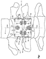
- Fig. 1 illustrates an apparatus 10 for use in retaining bone portions such as cervical vertebrae V1 and V2 of a human spinal column C in a desired spatial relationship.
- the spinal column C has an axis A which is a vertical axis of the human body.
- the apparatus 10 includes a pair of surgically implantable rods 12 and 14 (Figs. 1 and 2).
- the apparatus 10 also includes first and second members or plates 30 and 32 which engage the rods 12 and 14; three fasteners 38, 40, and 42 for connecting the first plate with the first vertebra V1; and three fasteners 44, 46, and 48 for connecting the second plate with the second vertebra V2.
- the first rod 12 (Fig. 1) is made of a suitable biocompatible material, such as titanium or stainless steel.
- the first rod 12 has an elongate cylindrical configuration and has a circular cross section taken in a plane extending perpendicular to the longitudinal central axis of the first rod.
- the first rod 12 has a smooth outer surface.
- a first end portion of the first rod 12 is formed as a cap 50.
- the first rod 12 also has a second end portion 52 opposite from the first end portion 50.
- the second rod 14 is identical to the first rod 12.
- the second rod 14 has a first end portion which is formed as a cap 54.
- the second rod 14 also has a second end portion 56 opposite from the first end portion 54.
- the rods 12 and 14 are bendable to a desired configuration to conform to a desired curvature of the spinal column C.
- the rods 12 and 14 together have sufficient strength and rigidity to maintain the vertebrae V1 and V2 in a desired spatial relationship.
- the rods 12 and 14 have a length which is sufficient to enable the rods to span at least the two vertebrae V1 and V2.
- the length of the rods 12 and 14 will depend upon the condition to be corrected and the number of vertebrae to be held in a desired spatial relationship relative to each other by the apparatus 10. If more than two vertebrae are to be held in a desired spatial relationship relative to each other by the apparatus 10, the rods 12 and 14 would be longer and more than two plates, such as the plates 30 and 32, may be used.
- the first plate 30 (Figs. 5 and 6) is made of a suitable biocompatible material, such as titanium or stainless steel.
- the first plate 30 includes a main body portion 60.
- the main body portion 60 of the first plate 30 has a planar outer side surface 62 for facing anteriorly or away from the first vertebra V1.
- the first plate 30 has an arcuate inner side surface 64 for facing posteriorly or toward the first vertebra V1.
- the inner side surface 64 of the first plate 30 may engage the anterior surface of the first vertebra V1 when the first plate is connected with the first vertebra as described below.
- the main body portion 60 of the first plate 30 has a central portion 66 which extends laterally between a first side portion 68 and a second side portion 70 of the first plate. Because the inner side surface 64 of the first plate 30 has an arcuate configuration, the central portion 66 of the first plate is relatively thin (as viewed in a direction from left to right in Fig. 3) as compared to the first side portion 68 and to the second side portion 70.
- the main body portion 60 of the first plate 30 also has first and second end portions 72 and 74.
- the first end portion 72 of the first plate 30 includes a planar first end surface 76 of the first plate 30.
- the second end portion 74 includes a planar second end surface 78 of the first plate 30.
- the second end surface 78 extends parallel to the first end surface 76.
- a first rod passage 80 is formed in the first side portion 68 of the first plate 30.
- the first rod passage 80 is an opening which extends between the first and second end surfaces 76 and 78 of the first plate 30 in a direction parallel to the planar outer side surface 62 of the first plate.
- the first rod passage 80 is defined by a cylindrical surface 81 and tapered pilot surfaces 83 and 84 at opposite ends of the cylindrical surface 81.
- the diameter of the cylindrical surface 81 is slightly greater than the diameter of the first rod 12, so that the first rod and the first plate 30 can be relatively movable.
- the second side portion 70 of the first plate 30 is a mirror image of the first side portion 68.
- a second rod passage 82 is formed in the second side portion 70 of the first plate 30.
- the second rod passage 82 is an opening which extends between the first and second end surfaces 76 and 78 of the first plate 30 in a direction parallel to the planar outer side surface 62 of the first plate.
- the second rod passage 82 extends parallel to the first rod passage 80.
- the second rod passage 82 is defined by a cylindrical surface 85 and tapered pilot surfaces 86 and 87 at opposite ends of the cylindrical surface 85.
- the diameter of the second rod passage 82 is the same as the diameter of the first rod passage 80.
- the diameter of the cylindrical surface 85 is slightly greater than the diameter of the second rod 14, so that the second rod and the first plate 30 can be relatively movable.
- a circular first fastener opening 90 extends through the central portion 66 of the first plate 30.
- the first fastener opening 90 has an axis 92 (Fig. 2) which extends perpendicular to the plane of the outer side surface 62 of the first plate 30.
- the axis 92 extends in a first direction as indicated by the arrow 94, that is, from right to left as viewed in Fig. 2, when the first plate 30 is mounted on the first vertebra V1.
- the first direction 94 extends perpendicular to the axes of the rods 12 and 14.
- the first fastener opening 90 is partially defined by a larger diameter cylindrical surface 96 (Fig. 6) which extends from the outer side surface 62 of the first plate 30 in a direction into the material of the central portion 66 of the first plate.
- the cylindrical surface 96 is centered on the axis 92 of the first fastener opening 90.
- the first fastener opening 90 is partially defined by a smaller diameter cylindrical surface 98 which extends from the inner side surface 64 of the first plate 30 in a direction into the material of the central portion 66 of the first plate to a location spaced radially inward from the surface 96.
- the cylindrical surface 98 is centered on the axis 92 of the first fastener opening 90.
- An annular shoulder surface 100 extends radially (relative to the axis 92) between the cylindrical surfaces 96 and 98.
- the shoulder surface 100 and the larger diameter cylindrical surface 96 define a recess 102 in the outer side surface 62 of the first plate 30.
- the main body portion 60 of the first plate 30 also includes a circular second fastener opening 110 formed at a location adjacent to, but spaced apart from, the first rod passage 80 in the first side portion 68 of the first plate.
- the second fastener opening 110 extends through both the second end surface 78 of the first plate 30 and the outer side surface 62 of the first plate.
- the second fastener opening 110 is partially defined by a larger diameter cylindrical surface 112 (Fig. 6) which extends from the outer side surface of the first plate 30 in a direction into the material of the first side portion 68 of the first plate.
- the cylindrical surface 112 is centered on an axis 114 (Fig. 2) of the second fastener opening 110.
- the cylindrical surface 112 is spaced apart from the first rod passage 80.
- the second fastener opening 110 is partially defined by a smaller diameter cylindrical surface 116 (Fig. 6) which extends from the inner side surface 64 of the first plate 30 in a direction into the material of the first side portion 68 of the first plate, to a location spaced radially inward from the surface 112.
- the cylindrical surface 116 is centered on the axis 114 of the second fastener opening 110.
- An annular shoulder surface 118 extends radially (relative to the axis 114) between the cylindrical surfaces 112 and 116.
- the shoulder surface 118 and the larger diameter cylindrical surface 112 define a recess 120 in the outer side surface 62 of the first plate 30.
- the axis 114 of the second fastener opening 110 extends transverse to the axis 92 of the first fastener opening 90. Specifically, the axis 114 (Fig. 3) of the second fastener opening 110 converges with the axis 92 of the first fastener opening 90 as viewed in a transverse plane at right angles to the vertical axis A, as can be seen from Fig. 3. In the illustrated embodiment, the axis 114 converges at an angle of about 10° with the axis 92 as viewed in this transverse plane.
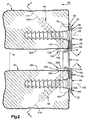
- the axis 114 of the second fastener opening 110 also converges with the axis 92 of the first fastener opening 90 as viewed in the sagittal plane, as can be seen in Fig. 2.
- the axis 114 converges at an angle of 45° with the axis 92 as viewed in the sagittal plane. It is contemplated that the angle of convergence as viewed in the sagittal plane could be in the range of from about 30° to about 60°.
- the main body portion 60 of the first plate 30 also includes a circular third fastener opening 130 formed at a location adjacent to, but spaced apart from, the second rod passage 82 in the second side portion 70 of the first plate.
- the third fastener opening 130 extends through both the second end surface 78 of the first plate 30 and the outer side surface 62 of the first plate.
- the third fastener opening 130 is partially defined by a larger diameter cylindrical surface 132 (Fig. 6) which extends from the outer side surface 62 of the first plate 30 in a direction into the material of the second side portion 70 of the first plate.
- the cylindrical surface 132 is centered on an axis 134 (Fig. 4) of the third fastener opening 130.
- the cylindrical surface 132 is spaced apart from the second rod passage 82.
- the third fastener opening 130 is partially defined by a smaller diameter cylindrical surface 136 (Fig. 6) which extends from the inner side surface 64 of the first plate 30 in a direction into the material of the second side portion 70 of the first plate, to a location spaced radially inward from the surface 32.
- the cylindrical surface 136 is centered on the axis 134 of the third fastener opening 130.
- An annular shoulder surface 138 extends radially (relative to the axis 134) between the cylindrical surfaces 132 and 136.
- the shoulder surface 138 and the larger diameter cylindrical surface 132 define a recess 140 in the outer side surface 62 of the first plate 30.
- the axis 134 (Fig. 3) of the third fastener opening 130 is coplanar with and extends parallel to the axis 114 of the second fastener opening 110.
- the axis 134 of the third fastener opening 130 extends transverse to the axis 92 of the first fastener opening 90.
- the axis 134 of the third fastener opening 130 converges with the axis 92 of the first fastener opening 90 as viewed in a transverse plane at right angles to the vertical axis A, as can be seen from Fig. 3.
- the axis 134 converges with the axis 92 at an angle of 10° as viewed in this transverse plane.
- the axis 134 of the third fastener opening 130 also converges with the axis 92 of the first fastener opening 90 as viewed in the sagittal plane, as can be seen from Fig. 2.
- the axis 134 converges with the axis 92 at an angle of 45° as viewed in the sagittal plane. It is contemplated that this angle of convergence as viewed in the sagittal plane could be in the range of from about 30° to about 60°.
- the first plate 30 includes a lip portion or lip 150 which is formed as one piece with the main body portion 60 of the first plate.
- the lip 150 best seen in Figs. 2 and 5, projects from the second end portion 74 of the main body portion 60 of the first plate 30.
- the lip 150 projects in the first direction 94 (Fig. 2) when the first plate 30 is mounted on the first vertebra V1.
- the lip 150 has a planar configuration as viewed in the first direction 94, for example, as seen in Fig. 2.
- the lip 150 has an arcuate configuration, as can be seen in Fig. 5, when viewed in a direction parallel to the plane of the outer side surface 62 of the first plate 30.
- the arcuate configuration of the lip 150 generally follows the arcuate configuration of the inner side surface 64 of the main body portion 60 of the first plate 30.
- the lip 150 extends continuously between the first and second side portions 68 and 70 of the first plate 30.
- the lip 150 may be discontinuous at one or more locations along the width of the plate 30.
- the lip 150 has an outer end surface 152 (Fig. 2) which is formed as an extension of the second end surface 78 of the main body portion 60 of the first plate 30.
- An opposite inner end surface 154 (Figs. 2 and 5) of the lip 150 extends parallel to the outer end surface 152.
- the lip 150 also has an inner side surface 156 which extends between the inner and outer end surfaces 154 and 152 of the lip 150.
- the second and third fastener openings 110 and 130 extend partially through the lip 150.
- the second fastener opening 110 as can be seen in Fig. 2, extends through the corner between, or intersection of, the lip 150 and the main body portion 60 of the first plate 30.
- the third fastener opening 130 also extends through the corner between, or intersection of, the lip 150 and the main body portion 60 of the first plate 30.
- the second plate 32 (Fig. 7) is generally similar in configuration to the first plate 30 (Fig. 5).
- the second plate 32 (Fig. 7) is configured, however, so that the head ends of fasteners received in certain fastener openings in the second plate are engageable with the rods 12 and 14 disposed in rod passages in the second plate. This engagement can block movement of the second plate 32 relative to the rods 12 and 14, in a manner described below.
- the second plate 32 includes a main body portion 160 which has a planar outer side surface 162 for facing anteriorly or away from the vertebra V2.
- the main body portion 160 also has an arcuate inner side surface 164 for facing posteriorly or toward the second vertebra V2.
- the inner side surface 164 of the second plate 32 may engage the anterior surface of the second vertebra V2 when the second plate is connected with the second vertebra as described below.
- the main body portion 160 has a central portion 166 which extends laterally between a first side portion 168 and a second side portion 170 of the second plate 32. Because the inner side surface 164 of the second plate 32 has an arcuate configuration, the central portion 166 of the second plate 32 is relatively thin (as viewed in a direction from left to right in Fig. 4) as compared to the first side portion 168 and to the second side portion 170.
- the main body portion 160 of the second plate 32 also has first and second end portions 172 and 174.
- the first end portion 172 of the second plate 32 includes a planar first end surface 176 of the second plate.
- the second end portion 174 of the second plate 32 includes a planar second end surface 178 of the second plate.
- the second end surface 178 extends parallel to the first end surface 176.
- a first rod passage 180 is formed in the first side portion 168 of the second plate 32.
- the first rod passage 180 is an opening which extends between the first and second end surfaces 176 and 178 in a direction parallel to the planar outer side surface 162 of the second plate 32.
- the first rod passage 180 is defined by a cylindrical surface 181 and tapered pilot surfaces 183 and 184 at opposite ends of the cylindrical surface 181.
- the diameter of the cylindrical surface 181 is slightly greater than the diameter of the first rod 12.
- a second rod passage 182 is formed in the second side portion 170 of the second plate 32.
- the second rod passage 182 is an opening which extends between the first and second end surfaces 176 and 178 in a direction parallel to the planar outer side surface 162 of the second plate 32.
- the second rod passage 182 extends parallel to and has the same diameter as first rod passage 180.
- the second rod passage 182 is defined by a cylindrical surface 185 and tapered pilot surfaces 186 and 187 at opposite ends of the cylindrical surface 185.
- the diameter of the cylindrical surface 185 is slightly greater than the diameter of the second rod 14.
- a circular first fastener opening 190 extends through the central portion 166 of the second plate 32.
- the first fastener opening 190 has an axis 192 (Figs. 2 and 4) which extends perpendicular to the plane of the outer side surface 162 of the second plate 32.
- the axis 192 extends in the first direction 94 when the second plate 32 is mounted on the second vertebra V2.
- the first fastener opening 190 is partially defined by a larger diameter cylindrical surface 196 (Fig. 8) which extends from the outer side surface 162 of the second plate 32 in a direction into the material of the central portion 166 of the second plate.
- the cylindrical surface 196 is centered on the axis 192 of the first fastener opening 190.
- the first fastener opening 190 is partially defined by a smaller diameter cylindrical surface 198 which extends from the inner side surface 164 of the second plate 32 in a direction into the material of the central portion 166 of the second plate, to a location spaced radially inward from the surface 196.
- the cylindrical surface 198 is centered on the axis 192 of the first fastener opening 190.
- An annular shoulder surface 200 extends radially (relative to the axis 192) between the cylindrical surfaces 196 and 198.
- the shoulder surface 200 and the larger diameter cylindrical surface 196 define a recess 202 in the outer side surface 162 of the second plate 32.
- the main body portion 160 of the second plate 32 also includes a circular second fastener opening 210 formed at a location adjacent to and intersecting the first rod passage 180 in the first side portion 168 of the second plate.
- the second fastener opening 210 extends through both the second end surface 178 of the second plate 32 and the outer side surface 162 of the second plate.
- the second fastener opening 210 is partially defined by a larger diameter cylindrical surface 212 (Fig. 8) which extends from the outer side surface 262 of the second plate 32 in a direction into the material of the first side portion 168 of the second plate.
- the cylindrical surface 212 is centered on an axis 214 (Figs. 2 and 4) of the second fastener opening 210.
- the cylindrical surface 212 intersects the cylindrical surface 181 which defines the first rod passage 180.
- the second fastener opening 210 overlaps a portion of the first rod passage 180.
- the second fastener opening 210 is partially defined by a smaller diameter cylindrical surface 216 which extends from the inner side surface 264 of the second plate 32 in a direction into the material of the first side portion 168 of the second plate, to a location spaced radially inward from the surface 212.
- the cylindrical surface 216 is centered on the axis 214 of the second fastener opening 210.
- An annular shoulder surface 218 extends radially (relative to the axis 214) between the cylindrical surfaces 212 and 216.
- the shoulder surface 218 and the larger diameter cylindrical surface 212 define a recess 220 in the outer side surface 262 of the second plate 32.
- the axis 214 of the second fastener opening 210 extends transverse to the axis 192 of the first fastener opening 190. Specifically, the axis 214 of the second fastener opening 210 converges with the axis 192 of the first fastener opening 190 as viewed in a transverse plane at right angles to the vertical axis A, as can be seen from Fig. 4. In the illustrated embodiment, the axis 214 converges with the axis 192 at angle of about 10° as viewed in this transverse plane.
- the axis 214 of the second fastener opening 210 also converges with the axis 192 of the first fastener opening 190 as viewed in the sagittal plane, as can be seen in Fig. 2.
- the axis 214 converges with the axis 192 at an angle of 45° as viewed in the sagittal plane. It is contemplated that this angle of convergence could be in the range of from about 30° to about 60° as viewed in the sagittal plane.
- the main body portion 160 of the second plate 32 also includes a circular third fastener opening 230 formed at a location adjacent to and intersecting the second rod passage 182 in the second side portion 170 of the second plate.
- the third fastener opening 230 extends through both the second end surface 178 of the second plate 32 and the outer side surface 162 of the second plate.
- the distance between the third fastener opening 230 in the second plate 32 and the second fastener opening 210 in the second plate is slightly less than the distance between the third fastener opening 130 in the first plate 30 and the second fastener opening 110 in the first plate.
- the third fastener opening 230 is partially defined by a larger diameter cylindrical surface 232 (Fig. 8) which extends from the outer side surface 262 of the second plate 32 in a direction into the material of the second side portion 170 of the second plate.
- the cylindrical surface 232 is centered on an axis 234 (Fig. 4) of the third fastener opening 230.
- the cylindrical surface 232 intersects the cylindrical surface 185 which defines the second rod passage 182.
- the third fastener opening 230 overlaps a portion of the second rod passage 182.
- the third fastener opening 230 is partially defined by a smaller diameter cylindrical surface 236 (Fig. 8) which extends from the inner side surface 264 of the second plate 32 into the material of the second side portion 170 of the second plate to a location spaced radially inward from the surface 232.
- the cylindrical surface 236 is centered on the axis 234 of the third fastener opening 230.
- An annular shoulder surface 238 extends radially (relative to the axis 234) between the cylindrical surfaces 232 and 236.
- the shoulder surface 238 and the larger diameter cylindrical surface 232 define a recess 240 in the outer side surface 162 of the second plate 32.
- the axis 234 of the third fastener opening 230 is coplanar with and extends parallel to the axis 214 of the second fastener opening 210.
- the axis 234 of the third fastener opening 230 extends transverse to the axis 192 of the first fastener opening 190.
- the axis 234 of the third fastener opening 230 converges with the axis 192 of the first fastener opening 190 as viewed in a transverse plane at right angles to the vertical axis A, as can be seen from Fig. 4.
- the axis 234 converges with the axis 192 at an angle of about 10° as viewed in this transverse plane.
- the axis 234 of the third fastener opening 230 also converges with the axis 192 of the first fastener opening 190 as viewed in the sagittal plane, as can be seen from Fig. 2.
- the axis 234 converges with the axis 192 at an angle of 45°. It is contemplated that this angle of convergence as viewed in the sagittal plane could be in the range of from about 30° to about 60°.
- the second plate 32 includes a lip portion or lip 250 which is formed as one piece with the main body portion 160 of the second plate.
- the lip 250 best seen in Figs. 4 and 7, projects from the second end portion 174 of the main body portion 160 of the second plate 32.
- the lip 250 projects in the first direction 94 (Fig. 2) when the second plate 32 is mounted on the second vertebra V2.
- the lip 250 has a planar configuration as viewed in the first direction 94, for example, as seen in Fig. 2.
- the lip 250 as viewed in a direction parallel to the plane of the outer side surface 162 of the second plate 32, has an arcuate configuration generally following the arcuate configuration of the inner side surface 164 of the main body portion 160 of the second plate 32.
- the lip 250 extends continuously between the first and second side portions 168 and 170 of the second plate 32.
- the lip 250 may be discontinuous at one or more locations along the width of the second plate 32.
- the lip 250 has an outer end surface 252 (Fig. 2) which is formed as an extension of the second end surface 178 of the main body portion 160 of the second plate 32.
- An opposite inner end surface 254 (Figs. 2 and 8) of the lip 250 extends parallel to the outer end surface 252.
- the lip 250 also has an inner side surface 256 which extends between the inner and outer end surfaces 252 and 254 of the lip 250.
- the second and third fastener openings 210 and 230 extend partially through the lip 250.
- the second fastener opening 210, as well as the third fastener opening 230 extend through the corner between, or intersection of, the lip 250 and the main body portion 160 of the second plate 32.
- the fasteners 38, 40, 42, 44, 46, and 48 which connect the first plate 30 with the first vertebra V1 and the second plate 32 with the second vertebra V2, are identical to each other. Because the fasteners 38-48 are identical, only the fastener 40 is described herein in detail.
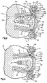
- the fastener 40 (Fig. 3) includes a sleeve 300 and an expander 310.
- the sleeve 300 has a hollow, elongate shank portion 302 centered on a longitudinal central axis 304 of the fastener 40.
- the shank portion 302 defines a cylindrical central opening 308 in the sleeve 300.
- a coarse external helical thread convolution 306 is formed on the outer peripheral surface of the shank portion 302 of the sleeve 300.
- the shank portion 302 of the sleeve 300 is radially and axially slotted so that the shank portion is expandable radially.
- a series of projections are formed on the inner surface of the sleeve 300 for engagement by the expander 310 to expand the shank portion 302 of the sleeve in a manner described below.
- a head end portion 314 of the sleeve 300 has a cylindrical outer side surface 316.
- An annular lip or rim 318 extends around the head end portion 314 of the sleeve 300 and projects radially outward from the outer side surface 316.
- the head end portion 314 of the sleeve 300 has a conical inner side surface 320 and a conical inner side surface 322.
- the conical inner side surface 322 merges with an internal thread convolution 324 formed on the sleeve 300.
- the head end portion 314 of the sleeve 300 is radially and axially slotted to define four segments 326 of the head end portion.
- the four segments 326 are movable radially relative to each other and to the axis 304 of the fastener 40 so that the head end portion 314 of the sleeve 300 is expandable radially.
- the expander 310 has a head end portion 340 and a shank portion 342.
- An inner end 344 of the shank portion 342 of the expander 310 is slightly larger in diameter than the cylindrical central opening 308 in the sleeve 300.
- the head end portion 340 of the expander 310 has an X-shaped driver slot 346 for receiving a driving tool for rotating the expander relative to the sleeve 300.
- the head end portion 340 has a conical outer side surface 348 and a conical outer side surface 350.
- the conical outer side surface 350 on the head end portion 340 of the expander 310 has a different angle of taper than does the conical inner side surface 322 on the head end portion 314 of the sleeve 300.
- the conical outer side surface 350 on the head end portion 340 of the expander 310 merges with an external thread convolution 352 formed on the expander 310.
- the external thread convolution 352 on the expander 310 screws into the internal thread convolution 324 on the sleeve 300.
- the rods 12 and 14 are first assembled with the plates 30 and 32. Specifically, the first rod 12 is inserted through the first rod passage 80 in the first plate 30 and through the first rod passage 180 in the second plate 32. One of the tapered pilot surfaces 83 and 84 on the first plate 30, and one of the tapered pilot surfaces 183 and 184 on the second plate 32, guide insertion of the first rod 12. The second rod 14 is inserted through the second rod passage 82 in the first plate 30 and through the second rod passage 182 in the second plate 32. One of the tapered pilot surfaces 86 and 87 on the first plate 30, and one of the tapered pilot surfaces 186 and 187 on the second plate 32, guide insertion of the second rod 14.
- the assembly of the rods 12 and 14 and the plates 30 and 32 is then positioned over the exposed anterior surface of the spinal column C.
- the first plate 30 (Fig. 2) is positioned adjacent to the first vertebra V1 so that the first end surface 154 on the lip 150 of the first plate engages a lower surface 360 on the first vertebra V1.
- the lower surface 360 on the first vertebra V1 faces toward the second vertebra V2.
- the second plate 32 is positioned adjacent to the second vertebra V2 so that the first end surface 254 on the lip 250 of the second plate engages an upper surface 362 on the second vertebra V2.
- the upper surface 362 on the second vertebra V2 faces toward the first vertebra V1.
- a suitable drill guide and drill (not shown) are used to drill fastener openings in the first vertebra V1 and in the second vertebra V2.
- the fasteners 38, 40 and 42 are inserted to connect the first plate 30 with the first vertebra.
- the insertion and securing of the fastener 40, although not necessarily performed first, will be described as exemplary.
- the sleeve 300 of the fastener 40 is inserted through the second fastener opening 110 in the first plate 30.
- the sleeve 300 of the fastener 40 is threaded into the drilled opening in the vertebra V1 in a known manner (not shown) to fix the sleeve in position in the vertebra V1.
- the unexpanded head portion 314 of the sleeve 300 is disposed in the recess 120 in the first plate 30.
- the expander 310 of the fastener 40 is then inserted into the sleeve 300.
- the externally threaded portion 352 of the expander 310 is screwed into the internal threads 324 on the sleeve 300.
- the inner end portion 344 of the expander 310 causes the shank portion 302 of the sleeve to expand radially outward, helping to lock the sleeve in place in the vertebra V1.
- the head portion 340 of the expander 310 engages the head portion 314 of the sleeve 300.
- the head portion 340 of the expander 310 wedges the locking segments 326 on the sleeve 300 radially outward into engagement with the first plate 30 to rigidly lock the fastener 40 in position relative to the first plate.
- the head of the fastener 40 is adjacent to the lip 150.
- the remaining fasteners 38 and 42 for the first plate 30 are similarly secured to the vertebra V1 and are rigidly locked to the first plate.
- the heads of the fasteners 38 and 42 are adjacent to the lip 150.
- the first plate 30 is securely connected with the first vertebra V1.
- the fasteners 44, 46 and 48 are similarly used to connect the second vertebra V2 and the second plate 32.
- the heads of the fasteners 44, 46, and 48 are adjacent to the lip 250.
- the fasteners 44, 46 and 48 are rigidly locked to the plate 32 and the plate 32 is securely connected with the second vertebra V2.
- the fastener 40 (as well as the fastener 42, not shown in Fig. 2) extends at an angle (upward as viewed in Fig. 2) to the lip 150. Accordingly, when the fasteners 40 and 42 are tightened into the first vertebra V1, the fasteners tend to draw the lip 150 of the first plate 30 tightly against the surface 360 of the vertebra, that is, in an upward direction as viewed in Fig. 2. At the same time, the fasteners 40 and 42, as well as the fastener 38, tend to draw the main body portion 60 of the first plate 30 tightly against the anterior surface of the first vertebra V1, that is, in a direction to the left as viewed in Fig. 2. Accordingly, it can be seen that tightening the fasteners 38, 40 and 42 tends to draw the first plate 30 in two directions against the first vertebra V1.
- the first fastener 38 has a longitudinal central axis which is coincident with the axis 92 of the first fastener opening 90 when the first fastener 38 is disposed in the first fastener opening 90 in the first plate 30.
- the longitudinal central axis 304 of the second fastener 40 is coincident with the axis 114 of the second fastener opening 110.
- the axis 92 of the first fastener opening 90 and the axis 114 of the second fastener opening 110 converge at an acute angle as viewed in the sagittal plane (Fig. 2). Therefore, the longitudinal axis of the first fastener 38 and the longitudinal axis 304 of the second fastener 40 converge at an acute angle as viewed in the sagittal plane (Fig. 2) when the first and second fasteners 38 and 40 connect the first plate 30 with the first vertebra V1.
- the axis of the first fastener 38 and the axis 304 of the second fastener 40 converge at an angle of about 45° as viewed in the sagittal plane. It is contemplated that this angle of convergence in the sagittal plane could be in the range of from about 30° to about 60°.
- the longitudinal central axis of the third fastener 42 is coincident with the axis 134 of the third fastener opening 130.
- the axis 92 of the first fastener opening 90 and the axis 134 of the third fastener opening 130 converge at an acute angle as viewed in the sagittal plane (Fig. 2). Therefore, the longitudinal axis of the first fastener 38 and the longitudinal axis of the third fastener 42 converge at an acute angle as viewed in the sagittal plane (Fig. 2) when the first and third fasteners 38 and 42 connect the first plate 30 with the first vertebra V1.
- the axis of the first fastener 38 and the axis of the third fastener 42 converge at an angle of about 45° as viewed in the sagittal plane. It is contemplated that this angle of convergence in the sagittal plane could be in the range of from about 30° to about 60°.
- the second plate 32 is, in a similar manner, secured in position relative to the second vertebra V2. Tightening the fasteners 44, 46 and 48 tends to draw the second plate 32 in two directions against the second vertebra V2.
- the axis of the first fastener 44 and the axis of the second fastener 46 converge at an acute angle as viewed in the sagittal plane (Fig. 2).
- the axis of the first fastener 44 and the axis of the third fastener 48 converge at an acute angle as viewed in the sagittal plane (Fig. 2).
- these axes converge at an angle of about 45° as viewed in the sagittal plane. It is contemplated that this angle of convergence in the sagittal plane could be in the range of from about 30° to about 60°.
- the outer fasteners 46 and 48 secure the second plate and the second vertebra.
- the fasteners 46 and 48 also serve to interlock the second plate 32 with the rods 12 and 14. This is because the locking segments 326 on the sleeves 300 of the fasteners 46 and 48 (Fig. 4) move radially outward into engagement with the rods 12 and 14, respectively, when each fastener's expander is fully screwed into the fastener's sleeve.
- the engagement between the fasteners 46 and 48 and the rods 12 and 14 blocks movement of the fasteners 46 and 48 relative to the rods.
- the first plate 30, in contrast, is movable relative to the rods 12 and 14, because the second and third fastener openings 110 and 130 are spaced apart from the rod passages 80 and 82. Therefore, the first plate 30 is movable relative to the second plate 32.
- the first vertebra V1 is movable vertically downward relative to the second vertebra V2.
- This relative movement allows for the maintaining of a load on bone graft placed between the vertebrae V1 and V2. If the first plate 30 were not movable vertically downward relative to the second plate 32, then the distance between the vertebrae V1 and V2 would be fixed. If bone graft were placed between the vertebrae V1 and V2 and the bone graft resorbed sufficiently, the bone graft could possibly shrink out of engagement with one or both of the vertebrae V1 and V2.
- Allowing relative movement of the plates 30 and 32 can help to maintain a desired load on bone graft placed between the vertebrae V1 and V2 and maintains the vertebrae in contact with the bone graft to facilitate bone growth.
- the lips 150 and 250 on the plates 30 and 32 are, preferably, configured so that the lips do not contact bone graft placed between the vertebrae.
- a dynamic (movable) plate such as the plate 30.
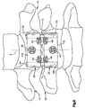
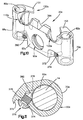
- two locking plates identical to the plate 32 can be used in the same apparatus 10.
- a system is illustrated in Fig. 9.
- the upper plate 32 (Fig. 9) is fixed in position relative to the vertebra V1 and to the rods 12 and 14.
- the lower plate 32 (Fig. 9) is fixed in position relative to the vertebra V2 and to the rods 12 and 14. Accordingly, the apparatus 10 (Fig. 9) blocks relative movement between the vertebrae V1 and V2.
- Figs. 10 and 11 illustrate a plate 30a which is constructed in accordance with a second embodiment of the present invention.
- the plate 30a can be substituted, in the apparatus 10, for the plate 30.
- the plate 30a is generally similar to the plate 30 (Figs. 5 and 6), and similar reference numerals are used to designate similar parts, with the suffix "a" added in Figs. 10 and 11 for clarity.
- a pair of set screws 370 are provided for engaging the rods 12 and 14 to block movement of the plate, and thereby its associated bone portion, relative to the rods.
- the outer side surface 62a of the plate 30a is recessed at 372 adjacent to the second rod passage 82a.
- a seat 374 extends inwardly from the recess 372 to a threaded opening 376.
- An inner end portion 378 of the opening 376 intersects with the second rod passage 82a.
- a second threaded opening 380 intersects the first rod passage 80a.
- fasteners such as the fasteners 38-42 are inserted through fastener openings 90a, 110a, and 130a in the plate 30a, to secure the plate to its associated bone portion.
- the head end portions of the fasteners for the plate 30a do not engage the rods 12 and 14, and do not clamp the rods against the plate 30a.
- a set screw 370 is threaded into the opening 376.
- An inner end portion 382 of the set screw 370 engages.the cylindrical outer surface of the second rod 14.
- the engagement of the set screw 370 with the second rod 14 clamps the rod against the second side portion 70a of the plate 30a.
- Another set screw 370 is threaded into the opening 380 to engage the first rod 12 and clamp the first rod against the first side portion 68a of the plate 30a.
- the set screws 370, the rods 12 and 14, and the plate 30a are interlocked.
- the plate 30a is movable relative to (along the length of) the rods 12 and 14. Because the plate 30a is fixed to its associated bone portion, then the bone portion also is movable relative to the rods 12 and 14.
- a portion of the lip 150a is removed at the location of the fastener openings 110a and 130a, to provide better visibility.
- This provides two lip segments 151 and 153 at the side portions 68a and 70a, respectively, of the plate 30a.
- the lip segments 151 and 153 are spaced apart on opposite sides of the longitudinal axis, or centerline, of the plate 30a.
- a portion of the lip 150a also is removed at the lateral center of the plate 30a, and a notch 384 is provided in the plate 30a, again to increase visibility.
Landscapes
- Health & Medical Sciences (AREA)
- Orthopedic Medicine & Surgery (AREA)
- Life Sciences & Earth Sciences (AREA)
- Neurology (AREA)
- Surgery (AREA)
- General Health & Medical Sciences (AREA)
- Veterinary Medicine (AREA)
- Engineering & Computer Science (AREA)
- Biomedical Technology (AREA)
- Heart & Thoracic Surgery (AREA)
- Public Health (AREA)
- Animal Behavior & Ethology (AREA)
- Molecular Biology (AREA)
- Medical Informatics (AREA)
- Nuclear Medicine, Radiotherapy & Molecular Imaging (AREA)
- Nursing (AREA)
- Vascular Medicine (AREA)
- Surgical Instruments (AREA)
- Prostheses (AREA)
- Medicines Containing Plant Substances (AREA)
- Investigating Or Analysing Biological Materials (AREA)
- Pharmaceuticals Containing Other Organic And Inorganic Compounds (AREA)
- Massaging Devices (AREA)
Claims (18)
- Vorrichtung (10) zum Festhalten erster und zweiter Wirbel (V1, V2) einer Wirbelsäule in einer gewünschten räumlichen Beziehung, welche Vorrichtung aufweist:dadurch gekennzeichnet, dass die genannte Längsachse (92) der genannten ersten Schraube (38) und die genannte Längsachse (114) der genannten zweiten Schraube (40), in einer Sagittalebene betrachtet, in einem spitzen Winkel konvergieren, wenn die erste und die zweite Schraube (38, 40) das genannte Glied (30) mit dem ersten Wirbel (V1) verbinden, wobei das genannte Glied (30), welches mit dem ersten Wirbel (V1) verbunden werden kann, einen Hauptteil (60) und einen Lippenteil (150) ausweist, welcher sich in einer ersten Richtung vom genannten Hauptteil (60) des genannten Gliedes (30) weg erstreckt, und wobei der genannte Lippenteil (150) des genannten Gliedes (30) mit einer gegen den zweiten Wirbel (V2) gerichteten Oberfläche des ersten Wirbels (V1) in Eingriff gebracht werden kann.ein oder zwei längsverlaufende Glieder (12, 14), welche längs der hinteren Oberfläche der Wirbelsäule positioniert werden können;ein Glied (30), welches mit dem ersten Wirbel (V1) verbunden werden kann, wobei das genannte Glied (30) erste und zweite Schraubenöffnungen (90, 110) und einen Teil (68, 70), welcher mit dem genannten längsverlaufende Glied (12, 14) in Eingriff gebracht werden kann, aufweist;eine erste Schraube (38), welche sich durch die genannte erste Schraubenöffnung (90) im genannten Glied (30) erstrecken kann, um das genannte Glied (30) mit dem ersten Wirbel (V1) zu verbinden, wobei die genannte erste Schraube (38) einen ersten Endteil zur Befestigung am ersten Wirbel (V1) und eine Längsachse (92) aufweist;eine zweite Schraube (40), welche sich durch die genannte zweite Schraubenöffnung (110) im genannten Glied (30) erstrecken kann, um das genannte Glied (30) mit dem ersten Wirbel (V1) zu verbinden, wobei die genannte zweite Schraube (40) einen ersten Endteil zur Befestigung am ersten Wirbel (V1) und eine Längsachse (114) aufweist; undMittel (32) zum Verbinden der genannten längsverlaufenden Glieder (12, 14) mit dem zweiten Wirbel (V2);
- Vorrichtung nach Anspruch 1, dadurch gekennzeichnet, dass die genannten ersten und zweiten Schrauben (38, 40) zweite Endteile aufweisen, welche den genannten ersten Endteilen gegenüber liegen, wobei der genannte erste Endteil der genannten ersten Schraube (38) vom genannten ersten Endteil der genannten zweiten Schraube (40) in einem ersten Abstand angeordnet ist, wenn die genannten ersten und zweiten Schrauben das genannte Glied (30) mit dem ersten Wirbel (V1) verbinden, und der genannte zweite Endteil der genannten ersten Schraube (38) vom genannten zweiten Endteil der genannten zweiten Schraube (40) in einem zweiten Abstand angeordnet ist, welcher grösser ist als der genannte erste Abstand, wenn die genannten ersten und zweiten Schrauben das genannte Glied (30) mit dem ersten Wirbel (V1) verbinden.
- Vorrichtung nach Anspruch 1, dadurch gekennzeichnet, dass das genannte Glied (30a) eine Klemmschraube (370) aufweist, welche am genannten längsverlaufenden Glied (12, 14) angreifen kann, um eine Bewegung des genannten Gliedes (30a) gegenüber dem genannten längsverlaufenden Glied (12, 14) zu blockieren, wenn die genannten ersten und zweiten Schrauben (38, 40) das genannte Glied (30a) mit dem zweiten Wirbel (V2) verbinden.
- Vorrichtung nach Anspruch 1, dadurch gekennzeichnet, dass das genannte Glied (30) einen Teil einer der genannten ersten und zweiten Schrauben (38, 40) umfasst, welcher an dem genannten längsverlaufenden Glied (12, 14) angreifen kann, um eine Bewegung der betreffenden Schraube (38, 40) und damit des genannten Gliedes (30) gegenüber dem genannten längsverlaufenden Glied (12, 14) zu blockieren, wenn die genannten ersten und zweiten Schrauben (38, 40) das genannte Glied (30) mit dem zweiten Wirbel (V2) verbinden.
- Vorrichtung nach Anspruch 1, dadurch gekennzeichnet, dass die genannte Längsachse (114) der genannten zweiten Schraube (40) sich, in der Sagittalebene betrachtet, unter einem Winkel im Bereich von 30 Grad bis 60 Grad gegenüber der genannten Längsachse (92) der genannten ersten Schraube (38) erstreckt.
- Vorrichtung nach Anspruch 5, dadurch gekennzeichnet, dass die genannte Längsachse (114) der genannten zweiten Schraube (40) sich, in der Sagittalebene betrachtet, unter einem Winkel von ungefähr 45 Grad gegenüber der genannten Längsachse (92) der genannten ersten Schraube (38) erstreckt.
- Vorrichtung nach Anspruch 1, dadurch gekennzeichnet, dass das genannte Glied (30) eine dritte Schraubenöffnung (130) aufweist, wobei die genannte Vorrichtung weiter eine dritte Schraube (42) aufweist, welche sich durch die genannte dritte Schraubenöffnung (130) im genannten Glied (30) hindurch erstrecken kann, um das genannte Glied (30) mit dem ersten Wirbel (V1) zu verbinden, und wobei die genannte dritte Schraube (42) einen ersten Endteil zur Verbindung mit dem ersten Wirbel (V1) und eine Längsachse (134) aufweist.
- Vorrichtung nach Anspruch 7, dadurch gekennzeichnet, dass die genannte zweite Schraube (40) und die genannte dritte Schraube (42) im Grossen und Ganzen koplanar angeordnet sind, wobei die genannte Längsachse (92) der genannten ersten Schraube (38) und die genannte Längsachse (134) der genannten dritten Schraube (42), in der Sagittalebene betrachtet, unter einem spitzen Winkel konvergieren, wenn die genannten ersten, zweiten und dritten Schrauben (38, 40, 42) das genannte Glied (30) mit dem ersten Wirbel (V1) verbinden.
- Vorrichtung nach Anspruch 1, dadurch gekennzeichnet, dass die genannten Mittel zum Verbinden des genannten längsverlaufenden Gliedes (12, 14) mit dem zweiten Wirbel (V2) ein zweites Glied (32), welches mit dem zweiten Wirbel (V2) verbunden werden kann, umfasst, wobei das genannte zweite Glied (32) umfasst:wobei die genannten Längsachsen (192, 214) der genannten ersten und zweiten Schrauben (44, 46), in einer Sagittalebene betrachtet, unter einem spitzen Winkel konvergieren, wenn die genannten ersten und zweiten zusätzlichen Schrauben (44, 46) das genannte zweite Glied (32) mit dem zweiten Wirbel (V2) verbinden.mindestens zwei Schraubenöffnungen (190, 210, 230) und einen Teil, welcher an dem genannten längsverlaufenden Glied (12, 14) angreifen kann;eine erste zusätzliche Schraube (44), welche sich durch eine erste (190) der genannten mindestens zwei Schraubenöffnungen im genannten zweiten Glied (32) hindurch erstrecken kann, um das genannte zweite Glied (32) mit dem zweiten Wirbel (V2) zu verbinden, wobei die genannte erste zusätzliche Schraube (44) einen ersten Endteil zur Verbindung mit dem zweiten Wirbel (V2) und eine Längsachse (192) aufweist;eine zweite zusätzliche Schraube (46), welche sich durch eine zweite (210) der genannten mindestens zwei Schraubenöffnungen im genannten zweiten Glied (32) hindurch erstrecken kann, um das genannte zweite Glied (32) mit dem zweiten Wirbel (V2) zu verbinden, wobei die genannte zweite zusätzliche Schraube (46) einen ersten Endteil zur Verbindung mit dem zweiten Wirbel (V2) und eine Längsachse (214) aufweist:
- Vorrichtung nach Anspruch 9, dadurch gekennzeichnet, dass das genannte erste Glied (30) Mittel aufweist, um eine Bewegung des genannten ersten Gliedes (30) gegenüber dem genannten längsverlaufenden Glied (12, 14) zu blockieren, wenn die genannten ersten und zweiten Schrauben (38, 40) das genannte erste Glied (30) mit dem ersten Wirbel (V1) verbinden, wobei das genannte zweite Glied gegenüber dem genannten längsverlaufenden Glied (12, 14) beweglich ist, wenn die genannten ersten und zweiten zusätzlichen Schrauben (44, 46) das genannte zweite Glied (32) mit dem zweiten Wirbel (V2) verbinden.
- Vorrichtung nach Anspruch 1, dadurch gekennzeichnet, dass der genannte Hauptteil (60) des genannten Gliedes (30) einen ersten Endteil (72) und einen zwischen dem genannten ersten Endteil (72 ) und dem zweiten Wirbel (V2) angeordneten zweiten Endteil (74) aufweist, wobei der genannte Hauptteil (60) erste und zweite Schraubenöffnungen (90, 110) aufweist, welche im genannten zweiten Endteil (74) angeordnet sind, wobei der genannte Lippenteil (150) vom genannten zweiten Endteil (74) vorspringt.
- Vorrichtung nach Anspruch 1, dadurch gekennzeichnet, dass der genannte Hauptteil (60) des genannten Gliedes (30) eine im Grossen und Ganzen ebene äussere Seitenoberfläche (62) aufweist, wobei der genannte Lippenteil (150) des genannten Gliedes (30) eine im Grossen und Ganzen ebene Gestalt aufweist, welche sich in einer Richtung quer zur Ebene der genannten äusseren Seitenoberfläche (62) des genannten Hauptteils (60) des genannten Gliedes (30) erstreckt.
- Vorrichtung nach Anspruch 1, dadurch gekennzeichnet, dass der genannte Hauptteil (60a) des genannten Gliedes (30a) erste und zweite, einander gegenüberliegende Seitenteile (68a, 70a) aufweist, wobei der genannte Lippenteil (150a) des genannten Gliedes (30a) ein erstes Segment (151) am genannten ersten Seitenteil (68a) und ein zweites Segment (153) am genannten zweiten Seitenteil (70a) aulweist.
- Vorrichtung nach Anspruch 13, dadurch gekennzeichnet, dass das genannte erste Lippensegment (151) in Abstand vom genannten zweiten Lippensegment (153) an gegenüberliegenden Seiten der Längsachse des genannten Gliedes (30a) angeordnet ist.
- Vorrichtung nach Anspruch 13, dadurch gekennzeichnet, dass der genannte Lippenteil (150) des genannten Gliedes (30) sich im Wesentlichen kontinuierlich längs des genannten Gliedes (30) zwischen ersten und zweiten Seitenteilen (68, 70) erstreckt.
- Vorrichtung nach Anspruch 1, dadurch gekennzeichnet, dass sie ein Paar längsverlaufender Glieder (12, 14) aufweist, welche längs der Wirbelsäule positioniert werden können, wobei das genannte Glied (32) erste und zweite Schraubenöffnungen (190, 210) und Teile, welche an den genannten zwei längsverfaufenden Gliedern (12, 14) angreifen können, aufweist.
- Vorrichtung nach Anspruch 1, dadurch gekennzeichnet, dass die genannte erste Schraube (38) und die genannte zweite Schraube (40) mit dem genannten Glied (30) fest verriegelt sind.
- Vorrichtung nach Anspruch 1, dadurch gekennzeichnet, dass die Drehung der ersten Schraube (38) und der zweiten Schraube (40) bewirkt, dass das genannte Plattenglied (30) in mindestens zwei Richtungen gegen den genannten Wirbel (V1) gezogen wird.
Applications Claiming Priority (2)
| Application Number | Priority Date | Filing Date | Title |
|---|---|---|---|
| US655851 | 1996-05-31 | ||
| US08/655,851 US5800433A (en) | 1996-05-31 | 1996-05-31 | Spinal column retaining apparatus |
Publications (3)
| Publication Number | Publication Date |
|---|---|
| EP0809971A2 EP0809971A2 (de) | 1997-12-03 |
| EP0809971A3 EP0809971A3 (de) | 1998-01-07 |
| EP0809971B1 true EP0809971B1 (de) | 2003-04-09 |
Family
ID=24630650
Family Applications (1)
| Application Number | Title | Priority Date | Filing Date |
|---|---|---|---|
| EP97106886A Expired - Lifetime EP0809971B1 (de) | 1996-05-31 | 1997-04-25 | System zum Festhalten der Wirbelsäule |
Country Status (10)
| Country | Link |
|---|---|
| US (2) | US5800433A (de) |
| EP (1) | EP0809971B1 (de) |
| JP (2) | JP3302611B2 (de) |
| KR (1) | KR100212354B1 (de) |
| CN (1) | CN1119125C (de) |
| AT (1) | ATE236581T1 (de) |
| AU (1) | AU695138B2 (de) |
| CA (1) | CA2203716C (de) |
| DE (1) | DE69720591T2 (de) |
| ES (1) | ES2196209T3 (de) |
Cited By (7)
| Publication number | Priority date | Publication date | Assignee | Title |
|---|---|---|---|---|
| US7204837B2 (en) | 2001-12-14 | 2007-04-17 | Paul Kamaljit S | Spinal plate assembly |
| US7255699B2 (en) | 2001-12-14 | 2007-08-14 | Paul Kamaljit S | Spinal plate assembly |
| US7740649B2 (en) | 2004-02-26 | 2010-06-22 | Pioneer Surgical Technology, Inc. | Bone plate system and methods |
| US8172885B2 (en) | 2003-02-05 | 2012-05-08 | Pioneer Surgical Technology, Inc. | Bone plate system |
| US8361126B2 (en) | 2007-07-03 | 2013-01-29 | Pioneer Surgical Technology, Inc. | Bone plate system |
| US8623019B2 (en) | 2007-07-03 | 2014-01-07 | Pioneer Surgical Technology, Inc. | Bone plate system |
| US8900277B2 (en) | 2004-02-26 | 2014-12-02 | Pioneer Surgical Technology, Inc. | Bone plate system |
Families Citing this family (170)
| Publication number | Priority date | Publication date | Assignee | Title |
|---|---|---|---|---|
| US5800433A (en) | 1996-05-31 | 1998-09-01 | Acromed Corporation | Spinal column retaining apparatus |
| US5843082A (en) * | 1996-05-31 | 1998-12-01 | Acromed Corporation | Cervical spine stabilization method and system |
| WO1998001076A1 (de) * | 1996-07-09 | 1998-01-15 | Synthes Ag Chur | Vorrichtung für die knochenchirurgie |
| ZA983955B (en) * | 1997-05-15 | 2001-08-13 | Sdgi Holdings Inc | Anterior cervical plating system. |
| US20040220571A1 (en) * | 1998-04-30 | 2004-11-04 | Richard Assaker | Bone plate assembly |
| US6533786B1 (en) | 1999-10-13 | 2003-03-18 | Sdgi Holdings, Inc. | Anterior cervical plating system |
| FR2778088B1 (fr) * | 1998-04-30 | 2000-09-08 | Materiel Orthopedique En Abreg | Implant anterieur notamment pour le rachis cervical |
| US6228085B1 (en) * | 1998-07-14 | 2001-05-08 | Theken Surgical Llc | Bone fixation system |
| US8343186B2 (en) | 2004-04-06 | 2013-01-01 | Arthrex, Inc. | Fully threaded suture anchor with transverse anchor pin |
| US9521999B2 (en) | 2005-09-13 | 2016-12-20 | Arthrex, Inc. | Fully-threaded bioabsorbable suture anchor |
| CA2366783C (en) | 1999-04-05 | 2008-01-29 | Lance Middleton | Artificial spinal ligament |
| US6234705B1 (en) | 1999-04-06 | 2001-05-22 | Synthes (Usa) | Transconnector for coupling spinal rods |
| US6283967B1 (en) | 1999-12-17 | 2001-09-04 | Synthes (U.S.A.) | Transconnector for coupling spinal rods |
| US6692503B2 (en) | 1999-10-13 | 2004-02-17 | Sdgi Holdings, Inc | System and method for securing a plate to the spinal column |
| WO2001030248A1 (en) | 1999-10-22 | 2001-05-03 | Reiley Mark A | Facet arthroplasty devices and methods |
| US7674293B2 (en) | 2004-04-22 | 2010-03-09 | Facet Solutions, Inc. | Crossbar spinal prosthesis having a modular design and related implantation methods |
| US7691145B2 (en) | 1999-10-22 | 2010-04-06 | Facet Solutions, Inc. | Prostheses, systems and methods for replacement of natural facet joints with artificial facet joint surfaces |
| US8187303B2 (en) | 2004-04-22 | 2012-05-29 | Gmedelaware 2 Llc | Anti-rotation fixation element for spinal prostheses |
| US6461359B1 (en) | 1999-11-10 | 2002-10-08 | Clifford Tribus | Spine stabilization device |
| US6235033B1 (en) | 2000-04-19 | 2001-05-22 | Synthes (Usa) | Bone fixation assembly |
| WO2001089428A2 (en) * | 2000-05-25 | 2001-11-29 | Neurortho Implants Design, Llc | Inter-vertebral disc prosthesis for rachis for an anterior surgery thereof |
| US20030229348A1 (en) * | 2000-05-25 | 2003-12-11 | Sevrain Lionel C. | Auxiliary vertebrae connecting device |
| AU6197901A (en) * | 2000-05-25 | 2001-12-03 | Lionel C Sevrain | Anchoring system for fixing objects to bones |
| US6277120B1 (en) | 2000-09-20 | 2001-08-21 | Kevin Jon Lawson | Cable-anchor system for spinal fixation |
| US6740088B1 (en) * | 2000-10-25 | 2004-05-25 | Sdgi Holdings, Inc. | Anterior lumbar plate and method |
| US6488683B2 (en) * | 2000-11-08 | 2002-12-03 | Cleveland Clinic Foundation | Method and apparatus for correcting spinal deformity |
| US6972019B2 (en) * | 2001-01-23 | 2005-12-06 | Michelson Gary K | Interbody spinal implant with trailing end adapted to receive bone screws |
| ATE336953T1 (de) * | 2001-02-13 | 2006-09-15 | Jeffrey E Yeung | Kompressionsvorrichtung und trokar zum reparieren einer zwischenwirbelprothese |
| US7169182B2 (en) | 2001-07-16 | 2007-01-30 | Spinecore, Inc. | Implanting an artificial intervertebral disc |
| US6673113B2 (en) | 2001-10-18 | 2004-01-06 | Spinecore, Inc. | Intervertebral spacer device having arch shaped spring elements |
| US6872210B2 (en) * | 2001-02-23 | 2005-03-29 | James P. Hearn | Sternum fixation device |
| FR2823096B1 (fr) | 2001-04-06 | 2004-03-19 | Materiel Orthopedique En Abreg | Plaque pour dispositif d'osteosynthese des vertebres l5 et s1, dispositif d'osteosynthese incluant une telle plaque, et instrument pour la pose d'une telle plaque |
| US6599290B2 (en) | 2001-04-17 | 2003-07-29 | Ebi, L.P. | Anterior cervical plating system and associated method |
| US7186256B2 (en) * | 2001-06-04 | 2007-03-06 | Warsaw Orthopedic, Inc. | Dynamic, modular, single-lock anterior cervical plate system having assembleable and movable segments |
| US7097645B2 (en) * | 2001-06-04 | 2006-08-29 | Sdgi Holdings, Inc. | Dynamic single-lock anterior cervical plate system having non-detachably fastened and moveable segments |
| EP1404225A4 (de) * | 2001-06-04 | 2009-09-16 | Warsaw Orthopedic Inc | Anteriores zervikales plattensystem mit ankern zum eingriff in wirbelkörper, verbindungsplatte und verfahren zu seiner anbringung |
| JP4283665B2 (ja) * | 2001-06-04 | 2009-06-24 | ウォーソー・オーソペディック・インコーポレーテッド | 可動セグメントを有する前方頸椎用動的平板 |
| US7044952B2 (en) | 2001-06-06 | 2006-05-16 | Sdgi Holdings, Inc. | Dynamic multilock anterior cervical plate system having non-detachably fastened and moveable segments |
| US7041105B2 (en) | 2001-06-06 | 2006-05-09 | Sdgi Holdings, Inc. | Dynamic, modular, multilock anterior cervical plate system having detachably fastened assembleable and moveable segments |
| US7713302B2 (en) * | 2001-10-01 | 2010-05-11 | Spinecore, Inc. | Intervertebral spacer device utilizing a spirally slotted belleville washer having radially spaced concentric grooves |
| US7771477B2 (en) | 2001-10-01 | 2010-08-10 | Spinecore, Inc. | Intervertebral spacer device utilizing a belleville washer having radially spaced concentric grooves |
| US6679883B2 (en) | 2001-10-31 | 2004-01-20 | Ortho Development Corporation | Cervical plate for stabilizing the human spine |
| US7766947B2 (en) | 2001-10-31 | 2010-08-03 | Ortho Development Corporation | Cervical plate for stabilizing the human spine |
| AR038680A1 (es) * | 2002-02-19 | 2005-01-26 | Synthes Ag | Implante intervertebral |
| FR2836370B1 (fr) * | 2002-02-27 | 2005-02-04 | Materiel Orthopedique En Abreg | Plaque d'ancrage pour dispositif d'osteosynthese de la colonne vertebrale, et dispositif la comprenant |
| US20080027548A9 (en) | 2002-04-12 | 2008-01-31 | Ferree Bret A | Spacerless artificial disc replacements |
| US8038713B2 (en) | 2002-04-23 | 2011-10-18 | Spinecore, Inc. | Two-component artificial disc replacements |
| US6706068B2 (en) | 2002-04-23 | 2004-03-16 | Bret A. Ferree | Artificial disc replacements with natural kinematics |
| US7001389B1 (en) | 2002-07-05 | 2006-02-21 | Navarro Richard R | Fixed and variable locking fixation assembly |
| US6989012B2 (en) * | 2002-07-16 | 2006-01-24 | Sdgi Holdings, Inc. | Plating system for stabilizing a bony segment |
| US7179260B2 (en) | 2003-09-29 | 2007-02-20 | Smith & Nephew, Inc. | Bone plates and bone plate assemblies |
| US20040116931A1 (en) * | 2002-12-17 | 2004-06-17 | Carlson Gregory D. | Vertebrae fixation device and method of use |
| US7575588B2 (en) * | 2003-02-03 | 2009-08-18 | Warsaw Orthopedic Inc. | Midline occipital vertebral fixation system |
| DE50313446D1 (de) | 2003-02-06 | 2011-03-10 | Synthes Gmbh | Zwischenwirbelimplantat |
| US6908484B2 (en) | 2003-03-06 | 2005-06-21 | Spinecore, Inc. | Cervical disc replacement |
| US7662182B2 (en) * | 2003-03-06 | 2010-02-16 | Spinecore, Inc. | Instrumentation and methods for use in implanting a cervical disc replacement device |
| US7278997B1 (en) | 2003-03-07 | 2007-10-09 | Theken Spine, Llc | Instrument guide and implant holder |
| US7819903B2 (en) | 2003-03-31 | 2010-10-26 | Depuy Spine, Inc. | Spinal fixation plate |
| US20050255114A1 (en) * | 2003-04-07 | 2005-11-17 | Nuvelo, Inc. | Methods and diagnosis for the treatment of preeclampsia |
| US7291152B2 (en) * | 2003-04-18 | 2007-11-06 | Abdou M Samy | Bone fixation system and method of implantation |
| US8100976B2 (en) * | 2003-04-21 | 2012-01-24 | Rsb Spine Llc | Implant subsidence control |
| US7985255B2 (en) * | 2003-04-21 | 2011-07-26 | Rsb Spine Llc | Implant subsidence control |
| US20170020683A1 (en) | 2003-04-21 | 2017-01-26 | Rsb Spine Llc | Bone plate stabilization system and method for its use |
| US8613772B2 (en) * | 2003-04-21 | 2013-12-24 | Rsb Spine Llc | Lateral mount implant device |
| US6984234B2 (en) * | 2003-04-21 | 2006-01-10 | Rsb Spine Llc | Bone plate stabilization system and method for its use |
| US8348982B2 (en) * | 2003-04-21 | 2013-01-08 | Atlas Spine, Inc. | Bone fixation plate |
| US7608104B2 (en) | 2003-05-14 | 2009-10-27 | Archus Orthopedics, Inc. | Prostheses, tools and methods for replacement of natural facet joints with artifical facet joint surfaces |
| US20040230304A1 (en) | 2003-05-14 | 2004-11-18 | Archus Orthopedics Inc. | Prostheses, tools and methods for replacement of natural facet joints with artifical facet joint surfaces |
| US6945974B2 (en) | 2003-07-07 | 2005-09-20 | Aesculap Inc. | Spinal stabilization implant and method of application |
| US6945975B2 (en) * | 2003-07-07 | 2005-09-20 | Aesculap, Inc. | Bone fixation assembly and method of securement |
| US7074238B2 (en) | 2003-07-08 | 2006-07-11 | Archus Orthopedics, Inc. | Prostheses, tools and methods for replacement of natural facet joints with artificial facet joint surfaces |
| US7763056B2 (en) * | 2003-08-18 | 2010-07-27 | Dalton Brian E | Cervical compression plate assembly |
| US20050049595A1 (en) | 2003-09-03 | 2005-03-03 | Suh Sean S. | Track-plate carriage system |
| US7857839B2 (en) | 2003-09-03 | 2010-12-28 | Synthes Usa, Llc | Bone plate with captive clips |
| US7909860B2 (en) | 2003-09-03 | 2011-03-22 | Synthes Usa, Llc | Bone plate with captive clips |
| US20050090822A1 (en) * | 2003-10-24 | 2005-04-28 | Dipoto Gene | Methods and apparatus for stabilizing the spine through an access device |
| US20050131406A1 (en) | 2003-12-15 | 2005-06-16 | Archus Orthopedics, Inc. | Polyaxial adjustment of facet joint prostheses |
| US20050165484A1 (en) * | 2004-01-22 | 2005-07-28 | Ferree Bret A. | Artificial disc replacement (ADR) fixation methods and apparatus |
| US20050165487A1 (en) * | 2004-01-28 | 2005-07-28 | Muhanna Nabil L. | Artificial intervertebral disc |
| US7311712B2 (en) | 2004-02-26 | 2007-12-25 | Aesculap Implant Systems, Inc. | Polyaxial locking screw plate assembly |
| US7344537B1 (en) | 2004-03-05 | 2008-03-18 | Theken Spine, Llc | Bone fixation rod system |
| US7942913B2 (en) | 2004-04-08 | 2011-05-17 | Ebi, Llc | Bone fixation device |
| US7914556B2 (en) | 2005-03-02 | 2011-03-29 | Gmedelaware 2 Llc | Arthroplasty revision system and method |
| US7051451B2 (en) | 2004-04-22 | 2006-05-30 | Archus Orthopedics, Inc. | Facet joint prosthesis measurement and implant tools |
| WO2006055186A2 (en) | 2004-10-25 | 2006-05-26 | Archus Orthopedics, Inc. | Spinal prosthesis having a modular design |
| US7406775B2 (en) | 2004-04-22 | 2008-08-05 | Archus Orthopedics, Inc. | Implantable orthopedic device component selection instrument and methods |
| US20050245933A1 (en) * | 2004-05-03 | 2005-11-03 | Sevrain Lionel C | Multi coaxial screw system |
| US8142462B2 (en) | 2004-05-28 | 2012-03-27 | Cavitech, Llc | Instruments and methods for reducing and stabilizing bone fractures |
| US7727266B2 (en) | 2004-06-17 | 2010-06-01 | Warsaw Orthopedic, Inc. | Method and apparatus for retaining screws in a plate |
| WO2006022644A1 (en) * | 2004-07-26 | 2006-03-02 | Innovative Spinal Design, Inc. | Bone fixation plate |
| US20060036250A1 (en) * | 2004-08-12 | 2006-02-16 | Lange Eric C | Antero-lateral plating systems for spinal stabilization |
| WO2006023671A1 (en) | 2004-08-18 | 2006-03-02 | Archus Orthopedics, Inc. | Adjacent level facet arthroplasty devices, spine stabilization systems, and methods |
| US7883510B2 (en) * | 2004-08-27 | 2011-02-08 | Depuy Spine, Inc. | Vertebral staples and insertion tools |
| US20060052870A1 (en) * | 2004-09-09 | 2006-03-09 | Ferree Bret A | Methods and apparatus to prevent movement through artificial disc replacements |
| CN1293849C (zh) * | 2004-09-14 | 2007-01-10 | 李郁松 | 上颈椎生理性内固定装置 |
| US7887566B2 (en) * | 2004-09-16 | 2011-02-15 | Hynes Richard A | Intervertebral support device with bias adjustment and related methods |
| US9615866B1 (en) | 2004-10-18 | 2017-04-11 | Nuvasive, Inc. | Surgical fixation system and related methods |
| US7621914B2 (en) * | 2004-10-28 | 2009-11-24 | Biodynamics, Llc | Adjustable bone plate |
| ATE524121T1 (de) | 2004-11-24 | 2011-09-15 | Abdou Samy | Vorrichtungen zur platzierung eines orthopädischen intervertebralen implantats |
| US7527640B2 (en) | 2004-12-22 | 2009-05-05 | Ebi, Llc | Bone fixation system |
| US20060195089A1 (en) * | 2005-02-03 | 2006-08-31 | Lehuec Jean-Charles | Spinal plating and intervertebral support systems and methods |
| US8496686B2 (en) | 2005-03-22 | 2013-07-30 | Gmedelaware 2 Llc | Minimally invasive spine restoration systems, devices, methods and kits |
| US7678113B2 (en) | 2005-04-19 | 2010-03-16 | Warsaw Orthopedic, Inc. | Antero-lateral plating systems and methods for spinal stabilization |
| US7674296B2 (en) | 2005-04-21 | 2010-03-09 | Globus Medical, Inc. | Expandable vertebral prosthesis |
| US8777959B2 (en) | 2005-05-27 | 2014-07-15 | Spinecore, Inc. | Intervertebral disc and insertion methods therefor |
| DE602006020094D1 (de) | 2005-09-12 | 2011-03-31 | Arthrex Inc | Ösennahtanker |
| US7955364B2 (en) | 2005-09-21 | 2011-06-07 | Ebi, Llc | Variable angle bone fixation assembly |
| WO2007038429A1 (en) * | 2005-09-27 | 2007-04-05 | Endius, Inc. | Methods and apparatuses for stabilizing the spine through an access device |
| WO2007130699A2 (en) * | 2006-01-13 | 2007-11-15 | Clifford Tribus | Spine reduction and stabilization device |
| US20070233089A1 (en) * | 2006-02-17 | 2007-10-04 | Endius, Inc. | Systems and methods for reducing adjacent level disc disease |
| US20100305704A1 (en) | 2006-02-27 | 2010-12-02 | Synthes Gmbh | Intervertebral implant with fixation geometry |
| WO2007103081A2 (en) | 2006-03-02 | 2007-09-13 | The Cleveland Clinic Foundation | Asymmetrical cervical fusion plate and method for use |
| US7799055B2 (en) * | 2006-07-07 | 2010-09-21 | Warsaw Orthopedic, Inc. | Minimal spacing spinal stabilization device and method |
| WO2008019397A2 (en) | 2006-08-11 | 2008-02-14 | Archus Orthopedics, Inc. | Angled washer polyaxial connection for dynamic spine prosthesis |
| US8262710B2 (en) | 2006-10-24 | 2012-09-11 | Aesculap Implant Systems, Llc | Dynamic stabilization device for anterior lower lumbar vertebral fusion |
| EP2206467B1 (de) | 2007-05-21 | 2013-02-20 | AOI Medical Inc. | Instrument mit aufblasbarem Teil zum Reduzieren eines Wirbelkompressionsbruchs und Tentakel zum Einfüllen von Knochenzement |
| US8409258B2 (en) | 2007-06-01 | 2013-04-02 | Polyvalor, Limited Partnership | Fusionless vertebral physeal device and method |
| US8882813B2 (en) * | 2007-10-19 | 2014-11-11 | Spinesmith Partners, L.P. | Locking mechanisms and associated methods |
| US9072548B2 (en) * | 2007-06-07 | 2015-07-07 | Anthem Orthopaedics Llc | Spine repair assembly |
| US8709054B2 (en) | 2007-08-07 | 2014-04-29 | Transcorp, Inc. | Implantable vertebral frame systems and related methods for spinal repair |
| WO2009021144A2 (en) * | 2007-08-07 | 2009-02-12 | Transcorp, Inc. | Device for variably adjusting intervertebral distraction and lordosis |
| US7867263B2 (en) * | 2007-08-07 | 2011-01-11 | Transcorp, Inc. | Implantable bone plate system and related method for spinal repair |
| US8430882B2 (en) * | 2007-09-13 | 2013-04-30 | Transcorp, Inc. | Transcorporeal spinal decompression and repair systems and related methods |
| US8323320B2 (en) * | 2007-09-13 | 2012-12-04 | Transcorp, Inc. | Transcorporeal spinal decompression and repair system and related method |
| US20090076516A1 (en) * | 2007-09-13 | 2009-03-19 | David Lowry | Device and method for tissue retraction in spinal surgery |
| US20090088604A1 (en) * | 2007-09-28 | 2009-04-02 | David Lowry | Vertebrally-mounted tissue retractor and method for use in spinal surgery |
| KR20100105580A (ko) | 2007-11-16 | 2010-09-29 | 신세스 게엠바하 | 낮은 프로파일 추간 임플란트 |
| EP2227181A1 (de) * | 2007-11-27 | 2010-09-15 | Transcorp, Inc. | Verfahren und systeme zur reparatur einer bandscheibe über einen transkorporalen weg |
| US8377132B2 (en) * | 2008-01-16 | 2013-02-19 | Aesculap Implant Systems, Llc | Standalone dynamic interbody |
| US8414651B2 (en) * | 2008-01-16 | 2013-04-09 | Aesculap Implant Systems, Llc | Dynamic interbody |
| CA2847598A1 (en) * | 2008-01-18 | 2009-07-23 | Spinecore, Inc. | Instruments and methods for inserting artificial intervertebral implants |
| US8480716B2 (en) | 2008-04-25 | 2013-07-09 | Pioneer Surgical Technology, Inc. | Bone plate system |
| US8636740B2 (en) * | 2008-05-08 | 2014-01-28 | Aesculap Implant Systems, Llc | Minimally invasive spinal stabilization system |
| CN101617959B (zh) * | 2008-07-04 | 2012-05-02 | 上海中医药大学附属曙光医院 | 用于制作大鼠脊柱亚脱位动物模型的外部连接固定装置 |
| US8328807B2 (en) | 2008-07-09 | 2012-12-11 | Icon Orthopaedic Concepts, Llc | Ankle arthrodesis nail and outrigger assembly |
| US8414584B2 (en) | 2008-07-09 | 2013-04-09 | Icon Orthopaedic Concepts, Llc | Ankle arthrodesis nail and outrigger assembly |
| US20100049252A1 (en) * | 2008-08-21 | 2010-02-25 | Southern Spine, Llc | Transverse Connector Device for Extending an Existing Spinal Fixation System |
| BRPI0921485A2 (pt) | 2008-11-07 | 2016-01-12 | Synthes Gmbh | montagem de placa acoplada e espaçador de intercorpo vertebral |
| US20100137916A1 (en) * | 2008-12-03 | 2010-06-03 | Warsaw Orthopedic, Inc., An Indiana Corporation | Spinal plates for stabilizing segments |
| US8721723B2 (en) | 2009-01-12 | 2014-05-13 | Globus Medical, Inc. | Expandable vertebral prosthesis |
| WO2010094032A2 (en) | 2009-02-16 | 2010-08-19 | Aoi Medical Inc. | Trauma nail accumulator |
| USD734853S1 (en) | 2009-10-14 | 2015-07-21 | Nuvasive, Inc. | Bone plate |
| WO2011057187A1 (en) | 2009-11-09 | 2011-05-12 | Centinel Spine, Inc. | Spinal implant with attachment system |
| US8740983B1 (en) | 2009-11-11 | 2014-06-03 | Nuvasive, Inc. | Spinal fusion implants and related methods |
| US8840668B1 (en) | 2009-11-11 | 2014-09-23 | Nuvasive, Inc. | Spinal implants, instruments and related methods |
| US8764806B2 (en) | 2009-12-07 | 2014-07-01 | Samy Abdou | Devices and methods for minimally invasive spinal stabilization and instrumentation |
| US8591585B2 (en) | 2010-04-12 | 2013-11-26 | Globus Medical, Inc. | Expandable vertebral implant |
| US8870880B2 (en) | 2010-04-12 | 2014-10-28 | Globus Medical, Inc. | Angling inserter tool for expandable vertebral implant |
| US9301850B2 (en) | 2010-04-12 | 2016-04-05 | Globus Medical, Inc. | Expandable vertebral implant |
| US8282683B2 (en) | 2010-04-12 | 2012-10-09 | Globus Medical, Inc. | Expandable vertebral implant |
| US8425569B2 (en) | 2010-05-19 | 2013-04-23 | Transcorp, Inc. | Implantable vertebral frame systems and related methods for spinal repair |
| US8562656B2 (en) | 2010-10-15 | 2013-10-22 | Warsaw Orrthopedic, Inc. | Retaining mechanism |
| US9220604B2 (en) | 2010-12-21 | 2015-12-29 | DePuy Synthes Products, Inc. | Intervertebral implants, systems, and methods of use |
| US9241809B2 (en) | 2010-12-21 | 2016-01-26 | DePuy Synthes Products, Inc. | Intervertebral implants, systems, and methods of use |
| US9358122B2 (en) | 2011-01-07 | 2016-06-07 | K2M, Inc. | Interbody spacer |
| US8845728B1 (en) | 2011-09-23 | 2014-09-30 | Samy Abdou | Spinal fixation devices and methods of use |
| US9241807B2 (en) | 2011-12-23 | 2016-01-26 | Pioneer Surgical Technology, Inc. | Systems and methods for inserting a spinal device |
| US20130226240A1 (en) | 2012-02-22 | 2013-08-29 | Samy Abdou | Spinous process fixation devices and methods of use |
| US9198767B2 (en) | 2012-08-28 | 2015-12-01 | Samy Abdou | Devices and methods for spinal stabilization and instrumentation |
| US9320617B2 (en) | 2012-10-22 | 2016-04-26 | Cogent Spine, LLC | Devices and methods for spinal stabilization and instrumentation |
| USD745159S1 (en) | 2013-10-10 | 2015-12-08 | Nuvasive, Inc. | Intervertebral implant |
| EP3151766B1 (de) * | 2014-06-03 | 2021-03-03 | Geldwert, MD, Josef J. | Chirurgisches implantat zur korrektur von hallux valgus oder ballenzehe |
| US9867718B2 (en) | 2014-10-22 | 2018-01-16 | DePuy Synthes Products, Inc. | Intervertebral implants, systems, and methods of use |
| USD858769S1 (en) | 2014-11-20 | 2019-09-03 | Nuvasive, Inc. | Intervertebral implant |
| US10857003B1 (en) | 2015-10-14 | 2020-12-08 | Samy Abdou | Devices and methods for vertebral stabilization |
| US10973648B1 (en) | 2016-10-25 | 2021-04-13 | Samy Abdou | Devices and methods for vertebral bone realignment |
| US10744000B1 (en) | 2016-10-25 | 2020-08-18 | Samy Abdou | Devices and methods for vertebral bone realignment |
| US11179248B2 (en) | 2018-10-02 | 2021-11-23 | Samy Abdou | Devices and methods for spinal implantation |
| US11877779B2 (en) | 2020-03-26 | 2024-01-23 | Xtant Medical Holdings, Inc. | Bone plate system |
| CN112294501B (zh) * | 2020-10-30 | 2021-09-10 | 东南大学 | 一种可调节与装配的动物椎体固定器械 |
Family Cites Families (28)
| Publication number | Priority date | Publication date | Assignee | Title |
|---|---|---|---|---|
| US3741205A (en) | 1971-06-14 | 1973-06-26 | K Markolf | Bone fixation plate |
| GB1551706A (en) * | 1975-04-28 | 1979-08-30 | Downs Surgical Ltd | Surgical implant |
| GB1551705A (en) * | 1975-04-28 | 1979-08-30 | Downs Surgicial Ltd | Surgial implant |
| US4289123A (en) | 1980-03-31 | 1981-09-15 | Dunn Harold K | Orthopedic appliance |
| CH648197A5 (de) * | 1980-05-28 | 1985-03-15 | Synthes Ag | Implantat und zu dessen befestigung an einem knochen dienende schrauben. |
| US5024213A (en) * | 1989-02-08 | 1991-06-18 | Acromed Corporation | Connector for a corrective device |
| DE3923995A1 (de) * | 1989-07-20 | 1991-01-31 | Lutz Biedermann | Stabilisierungselement fuer knochen |
| FR2658413B1 (fr) * | 1990-02-19 | 1997-01-03 | Sofamor | Dispositif d'osteosynthese pour la correction des deviations rachidiennes. |
| US5092893A (en) * | 1990-09-04 | 1992-03-03 | Smith Thomas E | Human orthopedic vertebra implant |
| US5152303A (en) * | 1991-06-18 | 1992-10-06 | Carl Allen | Anterolateral spinal fixation system and related insertion process |
| US5261911A (en) * | 1991-06-18 | 1993-11-16 | Allen Carl | Anterolateral spinal fixation system |
| US5180381A (en) | 1991-09-24 | 1993-01-19 | Aust Gilbert M | Anterior lumbar/cervical bicortical compression plate |
| ATE124238T1 (de) | 1992-05-18 | 1995-07-15 | Pina Vertriebs Ag | Implantat für die wirbeläule. |
| ZA937672B (en) * | 1992-10-22 | 1994-05-16 | Danek Medical Inc | Spinal rod transverse connector for supporting vertebral fixation elements |
| DE69320593T2 (de) * | 1992-11-25 | 1999-03-04 | Codman & Shurtleff, Inc., Randolph, Mass. | Knochenplattensystem |
| US5403314A (en) * | 1993-02-05 | 1995-04-04 | Acromed Corporation | Apparatus for retaining spinal elements in a desired spatial relationship |
| US5395372A (en) * | 1993-09-07 | 1995-03-07 | Danek Medical, Inc. | Spinal strut graft holding staple |
| JPH07106921A (ja) * | 1993-10-08 | 1995-04-21 | Uniden Corp | 高速走査無線受信機 |
| US5454812A (en) * | 1993-11-12 | 1995-10-03 | Lin; Chih-I | Spinal clamping device having multiple distance adjusting strands |
| FR2713473A1 (fr) * | 1993-12-13 | 1995-06-16 | Caffiniere De Jean Yves | Matériel d'ostéosynthèse vertébrale postérieure par barre transversale inter-pédiculaire. |
| US5522816A (en) * | 1994-03-09 | 1996-06-04 | Acromed Corporation | Transverse connection for spinal column corrective devices |
| US5662652A (en) | 1994-04-28 | 1997-09-02 | Schafer Micomed Gmbh | Bone surgery holding apparatus |
| US5498263A (en) * | 1994-06-28 | 1996-03-12 | Acromed Corporation | Transverse connector for spinal column corrective devices |
| US5683391A (en) * | 1995-06-07 | 1997-11-04 | Danek Medical, Inc. | Anterior spinal instrumentation and method for implantation and revision |
| US5683392A (en) * | 1995-10-17 | 1997-11-04 | Wright Medical Technology, Inc. | Multi-planar locking mechanism for bone fixation |
| US5681312A (en) * | 1996-05-31 | 1997-10-28 | Acromed Corporation | Spine construct with band clamp |
| US5713900A (en) * | 1996-05-31 | 1998-02-03 | Acromed Corporation | Apparatus for retaining bone portions in a desired spatial relationship |
| US5800433A (en) | 1996-05-31 | 1998-09-01 | Acromed Corporation | Spinal column retaining apparatus |
-
1996
- 1996-05-31 US US08/655,851 patent/US5800433A/en not_active Expired - Fee Related
-
1997
- 1997-04-25 DE DE69720591T patent/DE69720591T2/de not_active Expired - Fee Related
- 1997-04-25 CA CA002203716A patent/CA2203716C/en not_active Expired - Fee Related
- 1997-04-25 ES ES97106886T patent/ES2196209T3/es not_active Expired - Lifetime
- 1997-04-25 AT AT97106886T patent/ATE236581T1/de not_active IP Right Cessation
- 1997-04-25 EP EP97106886A patent/EP0809971B1/de not_active Expired - Lifetime
- 1997-04-29 AU AU19151/97A patent/AU695138B2/en not_active Ceased
- 1997-05-20 JP JP12997097A patent/JP3302611B2/ja not_active Expired - Fee Related
- 1997-05-28 CN CN97112102A patent/CN1119125C/zh not_active Expired - Fee Related
- 1997-05-29 KR KR1019970021485A patent/KR100212354B1/ko not_active Expired - Fee Related
-
1998
- 1998-08-28 US US09/141,920 patent/US6214005B1/en not_active Expired - Fee Related
-
2001
- 2001-11-15 JP JP2001350026A patent/JP2002191615A/ja active Pending
Cited By (9)
| Publication number | Priority date | Publication date | Assignee | Title |
|---|---|---|---|---|
| US7204837B2 (en) | 2001-12-14 | 2007-04-17 | Paul Kamaljit S | Spinal plate assembly |
| US7255699B2 (en) | 2001-12-14 | 2007-08-14 | Paul Kamaljit S | Spinal plate assembly |
| US8172885B2 (en) | 2003-02-05 | 2012-05-08 | Pioneer Surgical Technology, Inc. | Bone plate system |
| US7740649B2 (en) | 2004-02-26 | 2010-06-22 | Pioneer Surgical Technology, Inc. | Bone plate system and methods |
| US7909859B2 (en) | 2004-02-26 | 2011-03-22 | Pioneer Surgical Technology, Inc. | Bone plate system and methods |
| US8900277B2 (en) | 2004-02-26 | 2014-12-02 | Pioneer Surgical Technology, Inc. | Bone plate system |
| US8361126B2 (en) | 2007-07-03 | 2013-01-29 | Pioneer Surgical Technology, Inc. | Bone plate system |
| US8623019B2 (en) | 2007-07-03 | 2014-01-07 | Pioneer Surgical Technology, Inc. | Bone plate system |
| US9381046B2 (en) | 2007-07-03 | 2016-07-05 | Pioneer Surgical Technology, Inc. | Bone plate system |
Also Published As
| Publication number | Publication date |
|---|---|
| AU695138B2 (en) | 1998-08-06 |
| CN1119125C (zh) | 2003-08-27 |
| US6214005B1 (en) | 2001-04-10 |
| CN1169848A (zh) | 1998-01-14 |
| KR100212354B1 (ko) | 1999-08-02 |
| CA2203716C (en) | 2003-07-22 |
| DE69720591T2 (de) | 2003-11-20 |
| ATE236581T1 (de) | 2003-04-15 |
| AU1915197A (en) | 1997-12-04 |
| JP3302611B2 (ja) | 2002-07-15 |
| JPH1043200A (ja) | 1998-02-17 |
| US5800433A (en) | 1998-09-01 |
| JP2002191615A (ja) | 2002-07-09 |
| KR970076124A (ko) | 1997-12-10 |
| EP0809971A2 (de) | 1997-12-03 |
| EP0809971A3 (de) | 1998-01-07 |
| DE69720591D1 (de) | 2003-05-15 |
| CA2203716A1 (en) | 1997-11-30 |
| ES2196209T3 (es) | 2003-12-16 |
Similar Documents
| Publication | Publication Date | Title |
|---|---|---|
| EP0809971B1 (de) | System zum Festhalten der Wirbelsäule | |
| US6193720B1 (en) | Cervical spine stabilization method and system | |
| US6036693A (en) | Cervical spine stabilization method and system | |
| CA2203943C (en) | An apparatus for retaining bone portions in a desired spatial relationship | |
| CA2294902C (en) | Multi-axial bone screw | |
| US5810817A (en) | Spinal therapy apparatus | |
| EP1682016B1 (de) | Knochenfixationssystem mit befestigungsglied mit niedrigem profil | |
| US5735853A (en) | Bone screw for osteosynthesis | |
| US6315779B1 (en) | Multi-axial bone anchor system | |
| US5387212A (en) | Vertebral locking and retrieving system with central locking rod | |
| US8313510B2 (en) | Device for securing spinal rods | |
| EP1098601B1 (de) | Vorrichtung zur wirbelsäulenosteosynthese | |
| EP0809972A2 (de) | Verbindungselement für ein Stabilisierungssystem einer menschlichen Wirbelsäule | |
| AU762865B2 (en) | Device for securing spinal rods | |
| AU727838B2 (en) | Cervical spine stabilization method and system |
Legal Events
| Date | Code | Title | Description |
|---|---|---|---|
| PUAI | Public reference made under article 153(3) epc to a published international application that has entered the european phase |
Free format text: ORIGINAL CODE: 0009012 |
|
| PUAL | Search report despatched |
Free format text: ORIGINAL CODE: 0009013 |
|
| 17P | Request for examination filed |
Effective date: 19970522 |
|
| AK | Designated contracting states |
Kind code of ref document: A2 Designated state(s): AT BE CH DE ES FR GB IT LI NL SE |
|
| AK | Designated contracting states |
Kind code of ref document: A3 Designated state(s): AT BE CH DE ES FR GB IT LI NL SE |
|
| 17Q | First examination report despatched |
Effective date: 20000726 |
|
| GRAG | Despatch of communication of intention to grant |
Free format text: ORIGINAL CODE: EPIDOS AGRA |
|
| GRAG | Despatch of communication of intention to grant |
Free format text: ORIGINAL CODE: EPIDOS AGRA |
|
| GRAG | Despatch of communication of intention to grant |
Free format text: ORIGINAL CODE: EPIDOS AGRA |
|
| GRAH | Despatch of communication of intention to grant a patent |
Free format text: ORIGINAL CODE: EPIDOS IGRA |
|
| GRAH | Despatch of communication of intention to grant a patent |
Free format text: ORIGINAL CODE: EPIDOS IGRA |
|
| RAP1 | Party data changed (applicant data changed or rights of an application transferred) |
Owner name: DEPUY ACROMED, INC. |
|
| GRAA | (expected) grant |
Free format text: ORIGINAL CODE: 0009210 |
|
| AK | Designated contracting states |
Designated state(s): AT BE CH DE ES FR GB IT LI NL SE |
|
| REG | Reference to a national code |
Ref country code: GB Ref legal event code: FG4D |
|
| REG | Reference to a national code |
Ref country code: CH Ref legal event code: EP |
|
| PGFP | Annual fee paid to national office [announced via postgrant information from national office to epo] |
Ref country code: DE Payment date: 20030428 Year of fee payment: 7 |
|
| REG | Reference to a national code |
Ref country code: CH Ref legal event code: NV Representative=s name: ROTTMANN, ZIMMERMANN + PARTNER AG |
|
| REG | Reference to a national code |
Ref country code: SE Ref legal event code: TRGR |
|
| PGFP | Annual fee paid to national office [announced via postgrant information from national office to epo] |
Ref country code: NL Payment date: 20030831 Year of fee payment: 8 |
|
| ET | Fr: translation filed | ||
| REG | Reference to a national code |
Ref country code: ES Ref legal event code: FG2A Ref document number: 2196209 Country of ref document: ES Kind code of ref document: T3 |
|
| PLBE | No opposition filed within time limit |
Free format text: ORIGINAL CODE: 0009261 |
|
| STAA | Information on the status of an ep patent application or granted ep patent |
Free format text: STATUS: NO OPPOSITION FILED WITHIN TIME LIMIT |
|
| 26N | No opposition filed |
Effective date: 20040112 |
|
| PGFP | Annual fee paid to national office [announced via postgrant information from national office to epo] |
Ref country code: SE Payment date: 20040406 Year of fee payment: 8 |
|
| PGFP | Annual fee paid to national office [announced via postgrant information from national office to epo] |
Ref country code: FR Payment date: 20040408 Year of fee payment: 8 |
|
| PGFP | Annual fee paid to national office [announced via postgrant information from national office to epo] |
Ref country code: AT Payment date: 20040415 Year of fee payment: 8 |
|
| PGFP | Annual fee paid to national office [announced via postgrant information from national office to epo] |
Ref country code: ES Payment date: 20040416 Year of fee payment: 8 |
|
| PGFP | Annual fee paid to national office [announced via postgrant information from national office to epo] |
Ref country code: GB Payment date: 20040421 Year of fee payment: 8 |
|
| PGFP | Annual fee paid to national office [announced via postgrant information from national office to epo] |
Ref country code: CH Payment date: 20040428 Year of fee payment: 8 |
|
| PGFP | Annual fee paid to national office [announced via postgrant information from national office to epo] |
Ref country code: BE Payment date: 20040617 Year of fee payment: 8 |
|
| PG25 | Lapsed in a contracting state [announced via postgrant information from national office to epo] |
Ref country code: DE Free format text: LAPSE BECAUSE OF NON-PAYMENT OF DUE FEES Effective date: 20041103 |
|
| PG25 | Lapsed in a contracting state [announced via postgrant information from national office to epo] |
Ref country code: IT Free format text: LAPSE BECAUSE OF NON-PAYMENT OF DUE FEES;WARNING: LAPSES OF ITALIAN PATENTS WITH EFFECTIVE DATE BEFORE 2007 MAY HAVE OCCURRED AT ANY TIME BEFORE 2007. THE CORRECT EFFECTIVE DATE MAY BE DIFFERENT FROM THE ONE RECORDED. Effective date: 20050425 Ref country code: GB Free format text: LAPSE BECAUSE OF NON-PAYMENT OF DUE FEES Effective date: 20050425 Ref country code: AT Free format text: LAPSE BECAUSE OF NON-PAYMENT OF DUE FEES Effective date: 20050425 |
|
| PG25 | Lapsed in a contracting state [announced via postgrant information from national office to epo] |
Ref country code: SE Free format text: LAPSE BECAUSE OF NON-PAYMENT OF DUE FEES Effective date: 20050426 Ref country code: ES Free format text: LAPSE BECAUSE OF NON-PAYMENT OF DUE FEES Effective date: 20050426 |
|
| PG25 | Lapsed in a contracting state [announced via postgrant information from national office to epo] |
Ref country code: LI Free format text: LAPSE BECAUSE OF NON-PAYMENT OF DUE FEES Effective date: 20050430 Ref country code: CH Free format text: LAPSE BECAUSE OF NON-PAYMENT OF DUE FEES Effective date: 20050430 Ref country code: BE Free format text: LAPSE BECAUSE OF NON-PAYMENT OF DUE FEES Effective date: 20050430 |
|
| BERE | Be: lapsed |
Owner name: *DEPUY ACROMED INC. Effective date: 20050430 |
|
| PG25 | Lapsed in a contracting state [announced via postgrant information from national office to epo] |
Ref country code: NL Free format text: LAPSE BECAUSE OF NON-PAYMENT OF DUE FEES Effective date: 20051101 |
|
| EUG | Se: european patent has lapsed | ||
| REG | Reference to a national code |
Ref country code: CH Ref legal event code: PL |
|
| GBPC | Gb: european patent ceased through non-payment of renewal fee |
Effective date: 20050425 |
|
| PG25 | Lapsed in a contracting state [announced via postgrant information from national office to epo] |
Ref country code: FR Free format text: LAPSE BECAUSE OF NON-PAYMENT OF DUE FEES Effective date: 20051230 |
|
| NLV4 | Nl: lapsed or anulled due to non-payment of the annual fee |
Effective date: 20051101 |
|
| REG | Reference to a national code |
Ref country code: FR Ref legal event code: ST Effective date: 20051230 |
|
| REG | Reference to a national code |
Ref country code: ES Ref legal event code: FD2A Effective date: 20050426 |
|
| BERE | Be: lapsed |
Owner name: *DEPUY ACROMED INC. Effective date: 20050430 |