US7909859B2 - Bone plate system and methods - Google Patents
Bone plate system and methods Download PDFInfo
- Publication number
- US7909859B2 US7909859B2 US11/259,714 US25971405A US7909859B2 US 7909859 B2 US7909859 B2 US 7909859B2 US 25971405 A US25971405 A US 25971405A US 7909859 B2 US7909859 B2 US 7909859B2
- Authority
- US
- United States
- Prior art keywords
- plate
- bone
- retainer
- plate member
- retainers
- Prior art date
- Legal status (The legal status is an assumption and is not a legal conclusion. Google has not performed a legal analysis and makes no representation as to the accuracy of the status listed.)
- Active, expires
Links
- GMPHVYZTQKNUCB-UHFFFAOYSA-N C(C1CCC1)C1CCCC1 Chemical compound C(C1CCC1)C1CCCC1 GMPHVYZTQKNUCB-UHFFFAOYSA-N 0.000 description 1
Images


Classifications
-
- A—HUMAN NECESSITIES
- A61—MEDICAL OR VETERINARY SCIENCE; HYGIENE
- A61B—DIAGNOSIS; SURGERY; IDENTIFICATION
- A61B17/00—Surgical instruments, devices or methods
- A61B17/56—Surgical instruments or methods for treatment of bones or joints; Devices specially adapted therefor
- A61B17/58—Surgical instruments or methods for treatment of bones or joints; Devices specially adapted therefor for osteosynthesis, e.g. bone plates, screws or setting implements
- A61B17/68—Internal fixation devices, including fasteners and spinal fixators, even if a part thereof projects from the skin
- A61B17/80—Cortical plates, i.e. bone plates; Instruments for holding or positioning cortical plates, or for compressing bones attached to cortical plates
- A61B17/8033—Cortical plates, i.e. bone plates; Instruments for holding or positioning cortical plates, or for compressing bones attached to cortical plates having indirect contact with screw heads, or having contact with screw heads maintained with the aid of additional components, e.g. nuts, wedges or head covers
- A61B17/8042—Cortical plates, i.e. bone plates; Instruments for holding or positioning cortical plates, or for compressing bones attached to cortical plates having indirect contact with screw heads, or having contact with screw heads maintained with the aid of additional components, e.g. nuts, wedges or head covers the additional component being a cover over the screw head
-
- A—HUMAN NECESSITIES
- A61—MEDICAL OR VETERINARY SCIENCE; HYGIENE
- A61B—DIAGNOSIS; SURGERY; IDENTIFICATION
- A61B17/00—Surgical instruments, devices or methods
- A61B17/16—Instruments for performing osteoclasis; Drills or chisels for bones; Trepans
- A61B17/1613—Component parts
- A61B17/1615—Drill bits, i.e. rotating tools extending from a handpiece to contact the worked material
-
- A—HUMAN NECESSITIES
- A61—MEDICAL OR VETERINARY SCIENCE; HYGIENE
- A61B—DIAGNOSIS; SURGERY; IDENTIFICATION
- A61B17/00—Surgical instruments, devices or methods
- A61B17/16—Instruments for performing osteoclasis; Drills or chisels for bones; Trepans
- A61B17/1662—Instruments for performing osteoclasis; Drills or chisels for bones; Trepans for particular parts of the body
- A61B17/1671—Instruments for performing osteoclasis; Drills or chisels for bones; Trepans for particular parts of the body for the spine
-
- A—HUMAN NECESSITIES
- A61—MEDICAL OR VETERINARY SCIENCE; HYGIENE
- A61B—DIAGNOSIS; SURGERY; IDENTIFICATION
- A61B17/00—Surgical instruments, devices or methods
- A61B17/16—Instruments for performing osteoclasis; Drills or chisels for bones; Trepans
- A61B17/17—Guides or aligning means for drills, mills, pins or wires
- A61B17/1728—Guides or aligning means for drills, mills, pins or wires for holes for bone plates or plate screws
-
- A—HUMAN NECESSITIES
- A61—MEDICAL OR VETERINARY SCIENCE; HYGIENE
- A61B—DIAGNOSIS; SURGERY; IDENTIFICATION
- A61B17/00—Surgical instruments, devices or methods
- A61B17/16—Instruments for performing osteoclasis; Drills or chisels for bones; Trepans
- A61B17/17—Guides or aligning means for drills, mills, pins or wires
- A61B17/1739—Guides or aligning means for drills, mills, pins or wires specially adapted for particular parts of the body
- A61B17/1757—Guides or aligning means for drills, mills, pins or wires specially adapted for particular parts of the body for the spine
-
- A—HUMAN NECESSITIES
- A61—MEDICAL OR VETERINARY SCIENCE; HYGIENE
- A61B—DIAGNOSIS; SURGERY; IDENTIFICATION
- A61B17/00—Surgical instruments, devices or methods
- A61B17/56—Surgical instruments or methods for treatment of bones or joints; Devices specially adapted therefor
- A61B17/58—Surgical instruments or methods for treatment of bones or joints; Devices specially adapted therefor for osteosynthesis, e.g. bone plates, screws or setting implements
- A61B17/68—Internal fixation devices, including fasteners and spinal fixators, even if a part thereof projects from the skin
- A61B17/70—Spinal positioners or stabilisers, e.g. stabilisers comprising fluid filler in an implant
- A61B17/7059—Cortical plates
-
- A—HUMAN NECESSITIES
- A61—MEDICAL OR VETERINARY SCIENCE; HYGIENE
- A61B—DIAGNOSIS; SURGERY; IDENTIFICATION
- A61B17/00—Surgical instruments, devices or methods
- A61B17/56—Surgical instruments or methods for treatment of bones or joints; Devices specially adapted therefor
- A61B17/58—Surgical instruments or methods for treatment of bones or joints; Devices specially adapted therefor for osteosynthesis, e.g. bone plates, screws or setting implements
- A61B17/88—Osteosynthesis instruments; Methods or means for implanting or extracting internal or external fixation devices
- A61B17/8863—Apparatus for shaping or cutting osteosynthesis equipment by medical personnel
-
- A—HUMAN NECESSITIES
- A61—MEDICAL OR VETERINARY SCIENCE; HYGIENE
- A61B—DIAGNOSIS; SURGERY; IDENTIFICATION
- A61B17/00—Surgical instruments, devices or methods
- A61B17/56—Surgical instruments or methods for treatment of bones or joints; Devices specially adapted therefor
- A61B17/58—Surgical instruments or methods for treatment of bones or joints; Devices specially adapted therefor for osteosynthesis, e.g. bone plates, screws or setting implements
- A61B17/88—Osteosynthesis instruments; Methods or means for implanting or extracting internal or external fixation devices
- A61B17/92—Impactors or extractors, e.g. for removing intramedullary devices
-
- A—HUMAN NECESSITIES
- A61—MEDICAL OR VETERINARY SCIENCE; HYGIENE
- A61B—DIAGNOSIS; SURGERY; IDENTIFICATION
- A61B17/00—Surgical instruments, devices or methods
- A61B17/16—Instruments for performing osteoclasis; Drills or chisels for bones; Trepans
- A61B17/1655—Instruments for performing osteoclasis; Drills or chisels for bones; Trepans for tapping
-
- A—HUMAN NECESSITIES
- A61—MEDICAL OR VETERINARY SCIENCE; HYGIENE
- A61B—DIAGNOSIS; SURGERY; IDENTIFICATION
- A61B17/00—Surgical instruments, devices or methods
- A61B17/56—Surgical instruments or methods for treatment of bones or joints; Devices specially adapted therefor
- A61B17/58—Surgical instruments or methods for treatment of bones or joints; Devices specially adapted therefor for osteosynthesis, e.g. bone plates, screws or setting implements
- A61B17/68—Internal fixation devices, including fasteners and spinal fixators, even if a part thereof projects from the skin
- A61B17/80—Cortical plates, i.e. bone plates; Instruments for holding or positioning cortical plates, or for compressing bones attached to cortical plates
- A61B17/8004—Cortical plates, i.e. bone plates; Instruments for holding or positioning cortical plates, or for compressing bones attached to cortical plates with means for distracting or compressing the bone or bones
- A61B17/8009—Cortical plates, i.e. bone plates; Instruments for holding or positioning cortical plates, or for compressing bones attached to cortical plates with means for distracting or compressing the bone or bones the plate having a ratchet
-
- A—HUMAN NECESSITIES
- A61—MEDICAL OR VETERINARY SCIENCE; HYGIENE
- A61B—DIAGNOSIS; SURGERY; IDENTIFICATION
- A61B17/00—Surgical instruments, devices or methods
- A61B17/56—Surgical instruments or methods for treatment of bones or joints; Devices specially adapted therefor
- A61B17/58—Surgical instruments or methods for treatment of bones or joints; Devices specially adapted therefor for osteosynthesis, e.g. bone plates, screws or setting implements
- A61B17/88—Osteosynthesis instruments; Methods or means for implanting or extracting internal or external fixation devices
- A61B17/8875—Screwdrivers, spanners or wrenches
-
- A—HUMAN NECESSITIES
- A61—MEDICAL OR VETERINARY SCIENCE; HYGIENE
- A61B—DIAGNOSIS; SURGERY; IDENTIFICATION
- A61B90/00—Instruments, implements or accessories specially adapted for surgery or diagnosis and not covered by any of the groups A61B1/00 - A61B50/00, e.g. for luxation treatment or for protecting wound edges
- A61B90/03—Automatic limiting or abutting means, e.g. for safety
- A61B2090/033—Abutting means, stops, e.g. abutting on tissue or skin
- A61B2090/034—Abutting means, stops, e.g. abutting on tissue or skin abutting on parts of the device itself
-
- A—HUMAN NECESSITIES
- A61—MEDICAL OR VETERINARY SCIENCE; HYGIENE
- A61B—DIAGNOSIS; SURGERY; IDENTIFICATION
- A61B90/00—Instruments, implements or accessories specially adapted for surgery or diagnosis and not covered by any of the groups A61B1/00 - A61B50/00, e.g. for luxation treatment or for protecting wound edges
- A61B90/06—Measuring instruments not otherwise provided for
- A61B2090/061—Measuring instruments not otherwise provided for for measuring dimensions, e.g. length
Definitions
- the invention relates to bone plate systems and, more particularly, to a bone plate system including a retention system to retain the bone anchors against back from apertures of the plate, and to devices and methods for implanting and removing a bone plate system.
- bone may refer to a bone, or a bone fragment or portion, and the term may refer to a portion of a bone that is covered with another material, such as the endplates covering the top and bottom surface of a vertebra.
- These systems have been used to secure spinal vertebrae and, more specifically, cervical vertebrae.
- Bone plate systems are typically used to assist or direct spinal fusion or vertebral healing procedures. These procedures promote earlier post-operative patient mobility, decrease a need for post-operative collars, decrease the incidence of graft dislodgement if a graft is used, and improve success in correcting spinal deformities.
- fusion refers to the joining of materials, such as bone or graft material, and the fusion site is the entire region in which fusion may be desired.
- a shortcoming with bone plates is the backing out or loosening of the screws. If the screws loosen, the bones are not properly secure and may move relative to each other. This may compromise the ability to achieve optimal bone fusion and bone alignment, or it may lead to loss of graft material, and damage or loss of bone. Furthermore, when the plate is a dynamic or dynamized plate, such that at least some screws may move relative to the plate, these issues may be further compounded or exacerbated by a screw backing out.
- compression slots have been formed in a plate whereby a screw receiving bore is in the form of a slot with tapered walls, and a screw with a tapered shank is driven against the tapered wall such that a force between the shank and the slot is directed transverse to the shank. Accordingly, that force compresses the screw and the bone to which the screw is connected towards another bone connected to the plate.
- Another manner for permitting compressive force between joined bones is to utilize a dynamic plate having at least one elongated screw aperture that allows settling of the vertebrae by gravity by allowing at least one secured bone to move slightly relative to the plate.
- heretofore known arrangements of fixed and dynamized apertures in such plates provide less than optimal capacity for controlling the movement and/or compression between more than two levels of secured vertebrae.
- a bone plate assembly including a bone support plate having a plurality of paired apertures for receiving screws securing the plate to vertebrae and being curved about both a longitudinal and a lateral axis of the plate.
- a single, long flexible band is secured by retainers within a recessed portion or channel that extends longitudinally for substantially the entire extent of the top surface of the plate.
- the plate is depicted having increasingly elongated slots extending from a first end, and each slot permits translation relative to adjacent vertebrae and relative to the first end.
- the curve of a plate it is common for the curve of a plate to be adjusted for a particular patient's anatomy, such as via bending of the plate by a plate bending tool.
- the ends of the bands of the '833 patent are secured within end apertures so that, if the curve of the plate is decreased, the band ends may protrude from the plate.
- the band ends may pull out of the end apertures, and the bands or retainers may become loose from each other or the plate.
- the bands may be stretched which reduces their ability to shift as desired to permit screw securement and to return to their natural position and which may impair their general integrity.
- an increase of the curvature of the plate draws the bands closer to and into the holes, reducing the ability to properly seat the screw underneath the band.
- the '786 patent discloses a plate with a first pair of holes at a first end of the plate and a series of paired holes or slots extending from the first pair allowing for each vertebrae secured by the plate to translate toward the first plate end.
- the slots are increasingly large as they are arrayed away from the first hole pair. More specifically, the plate is fixedly secured to a first vertebra by the first pair of holes, and an adjacent pair of holes or slots is secured with a second, adjacent vertebra which is then permitted to translate toward the first vertebra.
- a third pair of slots is secured with a third vertebra, adjacent to the second vertebra, and is permitted to translate toward the second vertebra.
- the third vertebra must translate at least as much as the second vertebra, else the second and third vertebrae will separate due to the translation of the second vertebra toward the first vertebra.
- the third pair of slots must provide for the translation expected or permitted by the second pair of slots, as well as the expected translation by the third vertebra relative to the second vertebra.
- each pair of slots must be increasingly longer to permitted the cumulative amount of translation between the vertebra intermediate such pair of slots and the first pair of holes or slots.
- One problem with such a bone plate configuration is that forces on the plate and screws, such as moment arms from each level of screws to the lowest level, are greater.
- Another problem is that, though the screws may translate in the slots, this translation is not precisely controlled or predictable, and the greater translation that is required results in a greater ability for graft material to explant due to this lack of control, or be crushed by bearing a greater than desired load.
- Bone plate systems are provided for securing a plurality of bones or bone fragments in a predetermined relative orientation. Each bone plate system is secured with the bones via bone anchors in the form of screws received into bores in the plate.
- the screws are generally inhibited from backing out of the bone plate once secured by screw retainers.
- the retainers include at least two side portions, preferably straight side portions, positioned above the head of a screw when the screw is secured with the bone and with the plate in the bores. This provides at lest two line contacts between the retainer and the screw should the screw attempt to back out from its secured position.
- a single retainer is provided for each bore.
- adjustment of the longitudinal curve of the plate about a transverse axis extending orthogonal to the longitudinal axis of the plate can be made by adjusting the curve of the plate through plate portions spaced from the bores, preferably plate portions that extend longitudinally between the bores and which do not have the retainers or bores associated therewith. Accordingly, the location and position of the retainer relative to the plate and its bore are not affected by adjustment of the plate curvature, thus avoiding a potential problem in properly locating the screw in the bore below the retainer.
- the retainers are preferably pre-set during the manufacturing and assembly process. This helps to reduce surgeon or surgical technician error in properly installing the retainers, as well as reduce the ability for someone to alter the shape of the retainers themselves. Furthermore, the retainers require no additional steps to be properly positioned relative to the plate and, specifically, the screw openings or bores to limit screw back out. As the screw is driven through the bore and into the bone, the screw head forces the straight portions outward until the screw head has passed between and beyond the straight portions and the retainer in general. The retainer then returns to its original configuration so that the straight portions position themselves over the screw head.
- the retainers are preferably permanently secured with the bone plate.
- the retainers may have open ends while the bone plate may have recesses positioned closely adjacent and, preferably, contiguous with the bores.
- the retainers are assembled with the plate so that a portion of each retainer, such as the open end portions, may be received in the plate recesses. A portion of the plate may then be deformed over the open end portion in the plate recess to permanently secure the retainer to the plate.
- the retainer end portion is captured in such a manner as to permit adjustment of the retainer's assembled position.
- the retainers are received below a top surface of the bone plate.
- the retainers do not generally protrude beyond the surface of the plate so that they do not interfere with surrounding tissues.
- the deformed portion of the plate for capturing a portion of the retainers is deformed inward from the top surface of the plate into a recess for the retainer end portion, again minimizing the ability of surface features of the bone plate system to interfere with surrounding tissues.
- the retainers are positioned below the top surface of the plate, clearance may be provided between the retainer and a screw secured with the plate and located below the retainer.
- screws which can assume polyaxial orientations relative to the bore require a certain amount of pivoting within the bore. This pivoting by the screw results in a shifting or pivoting of the screw head top surface so that, when not aligned with a central axis of the bore, a portion of the screw head is positioned closer to the top surface than if the screw is aligned with the bore axis.
- the retainer accommodates this shifting or pivoting by the screw head by being positioned with a small clearance above where the screw head top surface would be in a secured positioned and aligned with the axis.
- the recesses for the retainer open end portion include pocket portions into which free ends of the retainer are positioned.
- the pocket portions have tab portions of the plate body formed in overlying relation thereabove. These tab portions are bent downwardly into the recess to permanently capture the free ends of the retainer in the pocket portions of the recess.
- the recesses are not along a bore-to-bore or screw-to-screw linear load path when the plate is secured with a plurality of bones
- the recesses are preferably positioned laterally of the longitudinal axis of the plate; that is, to a lateral side of the bores from the longitudinally extending direction of the spine to which the plate is secured. Accordingly, stress risers created by recesses and possibly the deformed tabs are positioned outside of the load path.
- a pair of bores is provided with a single recess for the respective retainers for the pair of bores.
- a pair of bores is provided along a single level or tier of the plate for a multi-level or tiered bone plate so that screws located therein secure with a single vertebra or portions thereof.
- the recess for capturing the retainer ends is provided between the bores, and plate portions are deformed into the recess to capture the ends of both retainers.
- the pair of bores may be provided with a single retainer which is secured in the recess and inhibits screw back out for the pair of screws located in the pair of bores.
- the bone plate systems may include dynamized bone plates for allowing translation of one or more of the bones towards at least one other of the bones. This allows compressive loads along the spine to shift or translate the bones after securement with the bone plate. Compressive loads on healing or fusing bones is believed to promote healing, both in terms of strength and time.
- the plate includes paired bores which are dynamized to permit a screw secured therein and to a bone to translate within the bore as the bone itself translates.
- the bore is elongated to have straight portions in the direction of the longitudinal axis of the spine.
- the retainers are elongated and generally have side portions, such as straight side portions, extending generally parallel to the bore straight portions and in the direction of the spinal axis.
- the elongated, or dynamized, retainers include free ends which are captured in the plate recess by deforming a portion of the plate inward, as discussed above.
- the free ends extend in the lateral direction relative to the longitudinal axis of the plate so that the recess of the plate for receiving the ends is not aligned with the linear load path that extends through the longitudinally aligned plate bores.
- the dynamized retainer includes first and second straight and parallel side portions where one of the side portions is shorter to provide a free end for being received in the recesses for capture with the plate. The retainer is configured so that the free end is located towards an end of the elongated bore and towards the end to which the screw head may translate.
- At least one level of bores for securing with a bone is non-dynamized.
- a plate having a level for securing with each bones may be provided where each level is secured without translation permitted.
- a two-level plate may be secured with a pair of bones, one of which is selected to translate relative to the plate and towards the other bone.
- a dynamized level or tier is provided for the translating bone and a non-dynamized level or tier is provided for the non-translating bone.
- the level or levels provided with non-dynamized bores may include surface features on a bottom side contacting the vertebra, the surface features embedding in or frictionally engaging with the vertebra to minimize the ability of the plate to shift or twist relative to that vertebra.
- the dynamized plate including the dynamized bores may span three or more bones, a level of bores provided for each bone, and control the translation of end bones towards an intermediate bone.
- the plate may have a non-dynamized level secured with a bone that is intermediate at least two other bones, each of the other bones being secured with a dynamized level so that they may translate towards the non-dynamized level, which need not be centered between the other levels. For a three-level plate, this minimizes the amount of translation required of the elongated, dynamized slots to the amount of translation required for the bone to which it is secured. This also serves to reduce moment arms produced by the compression force on the plate through the screws in the non-dynamized, intermediate bore.
- a tool for determining a plate size for a particular patient is provided.
- the tool is a sizing caliper having two legs which can be inserted together into a small incision and having a knob rotated to adjust the position of the legs relative to each other for determining a plate size.
- the sizing caliper may include a portion permitting the legs to be collapsed for withdrawal, and which then returns the legs to the measured position once withdrawn from the implant site so that the measurement is preserved.
- the sizing caliper may have a point or spike on one leg for securing in a selected position as the other leg is shifted relatively having a dull end or ball, or both legs may have ball shapes thereon for minimizing the risk of damage to surrounding tissues.
- a further aspect is providing a plate bending tool for adjusting the longitudinal curve of the bone plate to more closely follow a curve of the patient's spine along the longitudinal axis.
- the bending tool includes a space between a fulcrum and bending members, and the bone plate is compressed therein for altering the plate curvature.
- the plate may be inserted in a pre-determined position, and the fulcrum and bending members may be selectively positioned for increasing or decreasing the curvature of the plate.
- plate bending tool may include a pair of fulcra, one each for either increasing or decreasing the curvature of the plate.
- the bending members may include a pair of bending members for increasing the curvature, utilized with a first of the fulcra, and a pair of bending members for decreasing the curvature which are used with the second fulcra. Operation of handles forces bending members and a fulcrum to shift toward each other, with the plate therebetween, for adjusting the plate curvature.
- a tool for holding and positioning the bone plate system for implantation is provided in another aspect.
- the plate holding tool may have end tips received within recesses formed in sides and/or a bottom surface of the plate, and have opposed distally positioned portions, above the end tips, for positioning against a top surface of the plate so that the plate is held between the end tips and the opposed portions.
- the tool may have cooperating portions, such as ratcheting bars, so that the tool may be clamped with the plate.
- the opposed portions positioned against the top surface of the plate may include throughbores for cooperation with other components or tools utilized in the implantation of the bone plate system.
- the plate holder is constructed so that, when the end tips are secured with the plate, the throughbores are aligned with the plate bores.
- the throughbores of the plate holding tool include structure for cooperatively engaging with a guide tool.
- a guide tool for use with the plate holding tool so that a drill, tap, or the like, may be used for creating a hole in the bone for receiving the screw.
- the guide tool has end structure for cooperatively engaging with the plate holder.
- the end structure is generally a ball-shaped socket portion including resiliently deflectable fingers so that the socket portion may be compressed during reception into the throughbores of the plate holder.
- the guide tool and plate holder may cooperate to provide a pre-determined relative orientation, or may be pivotable so that an angle for the guide tool may be selected.
- an outer sleeve may be provided on the guide tool, and the sleeve may be reciprocated to compress or release the deflectable fingers for engaging or disengaging the guide tool from the plate holder.
- each tool may include a window or cut-out so that a surgeon has visual access into and through the bone plate bore with the plate holder and guide tool engaged. More specifically, the windows cooperate to allow a surgeon to see the surface of the vertebra in the area at which a screw is to be anchored.
- a driver for driving screws into the bones for securing the plate therewith includes a drive shaft with a terminal end thereon for engaging a screw head socket so that rotation of the drive shaft threadably forces the screw into a bone.
- the driver further may include an outer sleeve with external threads, which the screw head socket has an internally threaded portion. In this manner, the screw head may be threaded onto the sleeve to retain the screw therewith, either during implantation so that the screw does not separate and fall into the surgical field or during explantation when the screw is being removed from the bone.
- an extractor tool for use during extraction of the screw includes a terminal end including structure for forcing the retainer open so that the screw head may pass therethrough during removal.
- the extractor includes a central cannula through which the driver is inserted for engaging and removing a screw.
- the extractor may be frictionally around the driver during use, while in other forms the extractor may have a handle for manual control and manipulation.
- methods of implanting bone plate systems are disclosed.
- these methods may include selecting the numbers of levels on a plate, selecting the number of dynamized levels thereof, selecting the length of the plate such as with a sizing caliper, and adjusting the curvature of the plate such as with a plate bending tool.
- These methods may include selecting between screw tips such as self-tapping or self-drilling, and selecting among fixed or polyaxial screws.
- These methods may include preparing the implant site by holding the plate with a plate holder in a desired position so that the plate may be used as a template, by engaging a guide tool with the plate holder in a desired angle, and by directing a drill or tap or the like through the guide tool and plate holder to prepare a hole for receiving a screw.
- a driver may be used with the methods to engage and hold a screw thereon, the driver then driving the screw through a retainer located in the plate bore for preventing screw back-out. Should withdrawal of the screw be desired, the methods may include the use of an tool, such as an extractor tool cooperating with the driver, to open the retainer to permit the screw to be removed.
- FIG. 1 is a plan view of a bone plate system including features in accordance with the present invention and securing vertebrae in a particular orientation;
- FIG. 2 is a perspective view of the bone plate of FIG. 1 ;
- FIG. 3 is a plan view of the bone plate of FIG. 2 ;
- FIG. 4 is a cross-sectional view of the bone plate system of FIG. 1 taken along the line 4 - 4 ;
- FIGS. 5A and 5B are partial cross-sectional views of the bone plate with and without a retainer, respectively, located within a bore of the bone plate;
- FIG. 6 is a plan view of a retainer
- FIG. 7 is a side elevational of the retainer of FIG. 6 taken along the line 7 - 7 ;
- FIG. 8 is a plan view of another retainer
- FIG. 9 is a cross-sectional view of the bone plate system and a screw indicating insertion into the bone plate and a bone to which the bone plate system is to be secured;
- FIG. 10 is a cross-sectional view of the bone plate system and screw of FIG. 9 with the screw partially inserted into the bone plate and bone;
- FIG. 11 is a cross-sectional view of the bone plate system and screw of FIG. 9 with the screw fully inserted into the bone plate and bone;
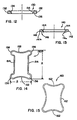
- FIG. 12 is a cross-sectional view of another retainer
- FIG. 13 is a cross-sectional view of another retainer
- FIG. 14 is a plan view of another retainer
- FIG. 15 is a plan view of another retainer
- FIG. 16 is a plan view of another embodiment of a bore plate system including a bone plate having a bore and a retainer located therein;
- FIG. 17 is a plan view of another embodiment of a bore plate system including a bone plate having a bore and a retainer located therein;
- FIG. 18 is a plan view of another embodiment of a bone plate system including a bone plate having a bore and a retainer located proximate thereof;
- FIG. 19 is a plan view of another embodiment of a bone plate system including a bone plate having bores and a retainer located proximate thereof;
- FIG. 20 is a cross-sectional view of the bone plate and retainer of FIG. 19 taken along the line 20 - 20 ;
- FIG. 21 is a plan view of a further embodiment of a retainer
- FIG. 22 is a side elevational view of the retainer of FIG. 21 ;
- FIG. 23 is an end view of the retainer of FIG. 21 ;
- FIG. 24 is a second plan view of the retainer of FIG. 21 ;
- FIG. 25 is a plan view of a further embodiment of a retainer
- FIG. 26 is a side elevational view of the retainer of FIG. 25 ;
- FIG. 27 is a plan view of a second form of the retainer of FIG. 25 ;
- FIG. 28 is a plan view of a further embodiment of a bone plate
- FIG. 29 is a side elevational view of the bone plate of FIG. 28 ;
- FIG. 30 is a cross-sectional view of the bone plate of FIG. 28 taken through the line 30 - 30 ;
- FIG. 31 is an end view of the bone plate of FIG. 28 ;
- FIG. 32 is a cross-sectional view of the bone plate of FIG. 28 taken through the line 32 - 32 ;
- FIG. 33 is a fragmentary cross-sectional view of the bone plate of FIG. 29 along the line 33 - 33 ;
- FIG. 34 is a fragmentary cross-sectional view of a bore of the bone plate of FIG. 30 ;
- FIG. 35 is a fragmentary bottom plan view of the bone plate of FIG. 28 ;
- FIG. 36 is a fragmentary side elevation view of the bone plate of FIG. 29 ;
- FIG. 37 is a plan view of a further embodiment of a bone plate similar to the bone plate of FIGS. 28-36 ;
- FIG. 38 is a side elevational view of the bone plate of FIG. 37 ;
- FIG. 39 is a cross-sectional view of the bone plate of FIG. 37 taken through the line 41 - 41 ;
- FIG. 40 is an end view of the bone plate of FIG. 37 ;
- FIG. 41 is a side elevational view of a driver for use with bone plates, retainers, and screws;
- FIG. 42 is a cross-sectional view of the driver of FIG. 41 ;
- FIG. 43 is a fragmentary view in partial cross-section of the driver of FIG. 41 ;
- FIG. 44 is a perspective view of a further embodiment of a bone plate
- FIG. 45 is a top plan view of the bone plate of FIG. 44 showing three levels having non-dynamized bores and showing a retainer operating in a single hole and a retainer operating in a pair of holes of one of the levels;
- FIG. 46 is an end elevational view of the bone plate of FIG. 44 showing a curvature in the lateral direction;
- FIG. 47 is a side elevational view of the bone plate of FIG. 44 showing a curvature in the longitudinal direction;
- FIG. 48 is a cross-sectional view of the bone plate taken through the line 48 - 48 of FIG. 45 ;
- FIG. 49 is a cross-sectional view of the bone plate taken through the line 49 - 49 of FIG. 46 ;
- FIG. 50 is a bottom plan view of the bone plate of FIG. 44 ;
- FIG. 51 is a top plan view of the retainer of FIG. 45 for operating in a single hole
- FIG. 52 is a top plan view of the retainer of FIG. 45 for operating in a pair of holes;
- FIG. 53 is a side elevation view of a bone plate fastener in the form of a self-drilling bone screw
- FIG. 54 is a cross-sectional view of the bone screw of FIG. 53 ;
- FIG. 55 is a cross-sectional view of a bone plate fastener in the form of a self-tapping bone screw
- FIG. 56 is a side elevational view of a sizing tool for measuring portions of a spine
- FIG. 57 is a cross-sectional view of the sizing tool taken through the line 57 - 57 of FIG. 56 ;
- FIG. 58 is a fragmentary view of a distal end of the sizing tool
- FIG. 59 is an exploded view of the sizing tool
- FIG. 60 is a perspective view of a bending tool for adjusting the shape of a bone plate in accordance with the present invention.
- FIG. 61 is a second perspective view of the bending tool
- FIG. 62 is a front plan view of the bending tool
- FIG. 63 is a perspective view generally of a front side of the bending tool taken from above thereof;
- FIG. 64 is a perspective view generally of the front side of the bending tool taken from below thereof;
- FIG. 65 is a rear plan view of the bending tool
- FIG. 66 is an exploded view of the bending tool
- FIG. 67 is a perspective view of a holding tool for positioning the plate during implantation
- FIG. 68 is a fragmentary view of a side of a distal end of the holding tool showing recess for a drill guide for implanting a bone plate;
- FIG. 69 is a second fragmentary view of a back side of the distal end of the holding tool.
- FIG. 70 is a front elevational view of the holding tool
- FIG. 71 is a third fragmentary view of a front side of the distal end of the holding tool showing the recess formed therein in phantom;
- FIG. 72 is a side elevation view of a drill guide for directing cutting members
- FIG. 73 is a cross-sectional view of the drill guide
- FIG. 74 is a side elevational view of an extractor tool for assisting in removal of bone anchors from an implanted bone plate;
- FIG. 75 is a rear elevational view of the extractor showing retainer-shifting tines
- FIG. 76 is a side elevational view of a holding pin for maintaining the position of a bone plate during implantation
- FIG. 77 is a side elevational view of an awl for creating a pilot hole for implanting a bone plate, shown without corresponding gripping handle;
- FIG. 78 is a side elevational view of a drill for opening a hole for implanting a bone plate, shown without corresponding gripping handle;
- FIG. 79 is a side elevational view of a tap for providing threads in a hole for implanting a bone plate, shown without corresponding gripping handle;
- FIG. 80 is a partially exploded view of a variable depth drill, shown without corresponding gripping handle;
- FIG. 81 is a top plan view of a position ratchet of the variable depth drill taken through the line 81 - 81 of FIG. 80 ;
- FIG. 82 is a top plan view of a further embodiment of a bone plate system similar to that of FIG. 45 including a bone plate having retainers secured therewith by deformed tabs and having two pairs of non-dynamized holes;
- FIG. 83 is a bottom plan view of the bone plate system of FIG. 82 showing the retainers intersecting with throughbores provided for securing the plate with screws;
- FIG. 84 is a perspective view of the bone plate system of FIG. 82 showing the deformed tabs capturing free ends of the retainers;
- FIG. 85 is a side elevational view of the bone plate system of FIG. 82 showing recesses for being manipulated by a plate holder and showing a curvature in a longitudinal direction;
- FIG. 86 is a plan view of the retainers of the bone plate system of FIG. 82 in an installed configuration and the bone plate in phantom;
- FIG. 87 is an exploded perspective top view of a bone plate system similar to that of FIG. 82 including a non-dynamized pair of holes intermediate two pairs of dynamized holes or slots and showing tabs in an undeformed state for providing a recess in which retainers may be received for securing thereto and proximate the holes;
- FIG. 88 is a bottom view corresponding to FIG. 87 showing recesses for being manipulated by the plate holder;
- FIG. 89 is a longitudinal cross-sectional view of a bone plate of the bone plate system of FIG. 87 showing retainer ends positioned within the recesses defined by the tabs prior to being deformed and showing a curvature in a longitudinal direction;
- FIG. 90 is a lateral cross-sectional view of the bone plate system of FIG. 87 showing recesses for receiving the retainers, geometry of the holes for receiving the screws, and a curvature in the lateral direction;
- FIG. 91 is a plan view of a retainer of the bone plate system of FIG. 87 for use with a dynamized hole;
- FIG. 92 is a side elevational view of an alternative bending tool for adjusting the shape of a bone plate by shifting an actuator handle relative to a handle of a body;
- FIG. 93 is an enlarged perspective view of an upper portion of the bending tool of FIG. 92 showing a positionable fulcrum forcable towards positionable bending assemblies by the actuator handle;
- FIG. 94 is an enlarged perspective view of the upper portion of the bending tool similar to the view of FIG. 93 with the fulcrum removed to show a support block for the fulcrum positioned within a guide of the body;
- FIG. 95 is a perspective front view of the fulcrum showing a concave surface and a convex surface thereon;
- FIG. 96 is a rear exploded view of the upper portion of the bending tool of FIG. 93 showing a positioning assembly for the fulcrum, one of the bending assemblies, and a rail within the guide for the support block;
- FIG. 97 is a front exploded view corresponding to FIG. 96 showing the positioning assembly for the fulcrum, one of the bending assemblies, and a rail within guide slots for the bending assemblies;
- FIG. 98 is a perspective view of an alternative embodiment of a sizing tool similar to that of FIGS. 56-59 showing a pair of legs having ball-shaped tips;
- FIG. 99 is a perspective view of an alternative embodiment of a holding tool similar to that of FIG. 67 showing a cut-out or window for viewing the screw head during implantation;
- FIG. 100 is a perspective view of a drill guide similar to that of FIG. 72 showing an engaging end for securing with a holding tool;
- FIG. 101 is a side elevational view of the engaging end of the drill guide of FIG. 100 showing a socket portion for forming a ball-and-socket coupling with a holding tool;
- FIG. 102 is a perspective view of the socket portion showing a window alignable with the window of the holding tool of FIG. 99 for viewing the screw head during implantation;
- FIG. 103 is a perspective view of the drill guide of FIG. 100 showing a bore opening for receiving a driver therein and showing a surface flat for alignment of the window with the holding tool window of FIG. 99 ;
- FIG. 104 is a side elevational view of a driver similar to that of FIG. 41 showing openings in an outer sleeve for promoting cleaning of the driver;
- FIG. 105 is an exploded perspective view of an extractor tool similar to that of FIG. 74 showing tines on a distal end for spreading a retainer to a position to permit removal of a screw from an implanted bone plate;
- FIG. 106 is a cross-sectional view of the extractor of FIG. 105 showing a longitudinal bore therethrough for receiving a driver and showing a recess for receiving a friction member for retaining the extractor and driver in rotational engagement during removal of a screw.
- the bone plate system is a dynamized plate, or has at least one set of dynamic holes, so that bones 12 may compress and shift toward each other, such as the bone plate system 10 depicted in FIG. 1 .
- a bone plate system 700 is illustrated as non-dynamized.
- a bone plate system may be provided including a bone plate where each bore thereof is dynamic, as is described herein, or non-dynamic, also described herein.
- a dynamized bone plate may utilize a combination of dynamic and non-dynamic bores.
- the bone plate system 10 assists in the healing and repair of damaged, fractured, or broken bones 12 .
- the bones 12 are adjacently located vertebrae of a spine, each spaced by a spinal disc 14 .
- the bone plate system 10 may also be used, accordingly, to assist in the healing necessary after trauma has been experienced by the spinal disc 14 .
- the bone plate system 10 may be utilized for stabilization and securement when adjacent vertebrae are fused, with or without the assistance of a bone graft between the vertebrae.
- the bone plate system 10 is used to secure the bones 12 (and any prosthetic or graft) in a desired spatial relationship.
- the desired spatial relationship between the bones 12 is generally vertical, such as the vertebrae would be in a normal, healthy spine when the person is standing.
- compression or loading of bones promotes healing of the bones or bone fragments and improves the integrity of the fusion therebetween.
- the weight of the person due to gravity, compresses those bones, such as a femur.
- the fusion of adjacent vertebrae can similarly benefit from using the weight of the person to compress the adjacent vertebrae.
- the dynamized bone plate system 10 preferably allows the bones 12 to shift relative to each other.
- the bone plate system 10 is designed to allow the bones 12 to compress in a manner dictated by the bone plate system 10 .
- the bone plate system 10 includes a bone plate 20 secured to the bones 12 with bone anchors which are, in the preferred form, bone screws 22 each having a head 26 and a threaded shank 28 .
- the bone screws 22 are preferably polyaxial for being driven into the bones 12 at an angle in relation to the plate desired by the surgeon or dictated by the surgical site. However, fixed angle screws, as described herein, may also be used.
- the plate 20 preferably has a pair of bores 24 forming a tier and being located at each level at which a bone 12 or bone cement is to be secured thereto.
- the plate 20 has an uppermost tier 30 , an intermediary tier 32 , and a lowermost tier 34 , each respectively in general proximity to an uppermost vertebrae 12 a , an intermediary 12 b vertebrae, and a lowermost vertebrae 12 c , where the plate 20 is utilized for securing the three vertebrae 12 a , 12 b , 12 c in a spatial relationship.
- any number of tiers could be provided for securing a plurality of bones, bone segments, or implanted materials.
- the plate 20 is a dynamized or dynamic plate.
- the plate 20 allows the bones 12 to compress towards each other by allowing at least a portion of the bone anchors in the form of screws 22 to shift relative to the plate 20 in a manner defined by the plate 20 .
- at least some of the bores 24 are dynamized bores 40 .
- the bores 24 of the uppermost and lowermost tiers 30 , 34 are dynamized bores 40
- the bores 24 of the intermediary tier 32 are non-dynamized bores 42 such that the non-dynamized bores 42 permit either no or minimal shifting of the screw head 26 and shank 28 within and/or relative to the non-dynamized bore 42 .
- the uppermost bone 12 a secured by the dynamized bores 40 of the uppermost tier 30 may translate toward the intermediary bone 12 b secured by the non-dynamized bores 42 of the intermediary tier 32 .
- the lowermost bone 12 c secured by the dynamized bores 40 of the lowermost tier 34 and the intermediary bone 12 b secured by the non-dynamized bores 42 of the intermediary tier 32 may translate relatively toward each other, in which case both the uppermost bone 12 a and intermediary bone 12 b are jointly translating towards the lowermost bone 12 c .
- the plate 20 may be equipped with two, or more, tiers 30 , 32 , 34 with each tier having non-dynamized bores 42 , or each tier having dynamized bores 40 , or any combination thereof, as desired.
- the plate 20 may have four tiers (not shown) including an uppermost tier, a lowermost tier, and superior and inferior intermediary tiers, preferably with one of the intermediary tiers having non-dynamized bores, most preferably the inferior intermediary tier having non-dynamized bores.
- the amount of translation by the three bones 12 a , 12 b , 12 c is such that the uppermost and lowermost bones 12 a , 12 c translate relatively towards the intermediary bone 12 b the proper amount.
- the uppermost tier 30 , 32 were provided with dynamized bores, the uppermost tier 30 would not only need to shift a distance towards the intermediary tier 32 , but would also need to shift more than the distance that the intermediary tier 32 shifts towards the lowermost tier 34 .
- the cumulative translation required for the uppermost tier 30 is minimized in the present arrangement, which improves effectiveness and minimizes explantation or crushing of a fusion graft. Furthermore, the present arrangement creates better fixation between the plate 20 and the bones 12 by reducing respective moment arms between the screws 22 of the intermediary tier 32 and screws 22 of the uppermost and lowermost tiers 30 , 34 .
- the dynamized bore 40 has an interior surface 50 with a racetrack, or oval, shape for receiving the screw head 26 where a lowermost portion 50 a of the interior surface 50 defines a racetrack-shaped throughbore 52 for receiving the screw shank 28 .
- a racetrack shape refers to a shape with oppositely oriented arcuate portions joined by straight portions. Accordingly, when a screw 22 is located within the dynamized bore 40 and secured in a bone 12 , the screw 22 can shift towards the center (the intermediary tier 32 ) of the plate 20 due to compression of the bones 12 .
- the screw head 26 can translate along the interior surface 50 , and the screw shank 28 can translate within the throughbore 52 , such translation being due to the weight of the erect person exerting a compression force along the spine.
- the interior surface 50 and throughbore 52 define the path of translation or shifting for the screw 22 .
- the dynamized and non-dynamized bores 40 , 42 have generally similar construction, with some notable differences.
- the non-dynamized bores 42 have an interior surface 60 for receiving the screw head 26 , and the interior surface 60 has a lowermost portion 60 a defining a throughbore 62 for receiving the screw shank 28 .
- the interior surface 60 and lowermost portion 60 a generally correspond to the interior surface 50 and lowermost portion 50 a of the dynamized bore.
- the interior surface 60 , lowermost portion 60 a , and throughbore 62 of the non-dynamized bore 42 are not racetrack-shaped, instead being generally circular, so that the screw 22 received therein is not permitted to shift or translate relative to the plate 20 due to compression force on the spine when the screw is secured to the plate 20 and the bone 12 .
- the non-dynamized bores 42 and features thereof for receiving a screw 22 are generally circular, while the dynamized bores 40 are elongated from a circle to have arcuate or circular ends with generally straight sections therebetween. Therefore, a lateral cross-section of a bore 24 , whether dynamized or non-dynamized, includes the same general features.
- FIG. 4 A plate 20 with representative pairs of bores 24 and screws 22 located therein is depicted in FIG. 4 .
- Each bore 24 has an inner surface 70 and a lowermost portion 70 a defining a throughbore 72 corresponding to the above described interior surfaces 50 , 60 , lowermost portions 50 a , 60 a , and throughbores 52 , 62 of the dynamized and non-dynamized bores 40 , 42 .
- the screw head 26 secures against the inner surface 70
- the screw shank 28 extends from the throughbore 72 and is secured within the bone 12 .
- a bridge or neck 27 portion connects the head 26 to the shank 28 .
- Each portion of the screw 22 other than helical threads of the shank 28 , is generally circular.
- the preferred screw 22 is polyaxial so that the screw may be driven through the bore 24 at a selected angle. Accordingly, the screw head 26 is larger than the screw shank 28 and the throughbore 72 , and the screw shank 28 is smaller than the throughbore 72 .
- the inner surface 70 has a brace surface 74 within which the bridge 27 of the screw 22 is positioned, the bridge 27 being smaller in diameter than the bore 24 within the brace surface 74 .
- the brace surface 74 transitions to a seat surface 78 at a shoulder position 80 .
- the screw head 26 rests against the shoulder position 80 , and the screw head 26 has an arcuate profile 82 that is able to seat properly against the shoulder 80 at the selected angle, as is depicted in FIG. 4 .
- the neck or bridge 27 is sized relative to the bore 24 within the brace surface 74 to allow the proper amount of angulation for the screw 22 to be pivoted for a selected angle. That is, greater difference in diametral size of the neck 27 and the bore 24 within the brace surface 74 permits greater pivoting extent for the screw 22 located therein.
- the shoulder 80 may have a number of constructions, such as simply an edge, or may be a chamfer, for instance.
- the seat surface 78 is preferably larger in diameter than the screw head 26 to provide clearance so that the screw 22 may be mounted in a selected angle.
- the seat surface 78 and screw head 26 may be spherical with closely matched diameters so that the screw head 26 may polyaxially slide against the seat surface 78 for driving the screw 22 in the bone 12 at the selected angle.
- the bone plate system 10 includes anchor retainers 100 , and preferably a retainer 100 is provided for each bore 24 .
- a retainer 100 is provided above the seat surface 78 .
- the screw head 26 has a height H 1 that is less than a height H 2 of the seat surface 78 . The height differential between H 1 and H 2 allows the screw 22 to pivot a predetermined amount before the screw head top surface 29 interferes with the retainer 100 when it is pivoted.
- the top surface 29 of the screw 22 is generally positioned below a lower edge 90 a of the recess 90 when the screw 22 is secured straight through the bore 24 , or is positioned below or generally coincident with the lower edge 90 a when the screw is secured at a selected pivoted angle.
- the inner surface 70 has a receiving portion 92 that terminates at a top edge 21 meeting with a top surface 20 a of the plate 20 .
- each described portion of the inner surface 70 is generally circular in shape.
- each described portion of the inner surface 70 for a dynamized bore 40 is generally circular at the arcuate ends E and is straight for the straight sides S (see FIG. 3 ).
- each retainer 100 is over top surface 29 of the screw head 26 such that the retainer 100 prevents the screw 22 from backing out through the bore 24 .
- the retainers 100 are preferably preset in the plate 20 during the assembly process such that a surgeon can handle the plate 20 and retainers 100 as a single unit.
- the screws 22 may be driven into the bones 12 to secure the plate 20 thereto, and the retainers 100 may then be inserted to prevent back-out of the screws 22 .
- FIG. 1 the plate 20 is shown secured to bones 12 with screws 22 , and the screws 22 are prevented from backing out by the retainers 100 .
- FIGS. 6-8 depict retainers 100 and, more particularly, depict a retainer 102 for a non-dynamized bore 42 (see FIG. 6 ) and a retainer 104 for a dynamized bore 40 (see FIG. 8 ).
- Each retainer 102 , 104 has a closed end 110 , an open end 112 opposite the closed end 110 , and straights 114 located between the closed and open ends 110 , 112 .
- the retainer 100 is held within the plate 20 by the recess 90 .
- the straights 114 of the retainer 100 Prior to the screw 22 being inserted into the plate 20 , the straights 114 of the retainer 100 are positioned in a static position as is depicted in FIG. 9 . More specifically, the straights 114 extend through the bore 24 to interfere with the path of the screw head 26 to contact the seat surface 78 . As the screw 22 is driven into the bone 12 , the screw head 26 contacts the straights 114 , as is depicted in FIG. 10 . As the screw 22 continues into the bone 12 and plate 20 , the arcuate profile 82 of the screw head 26 cams against the straights 114 and forces, wedge-like, the straights 114 away from each other and into the recess 90 .
- the retainer 100 generally returns to its static position such as that prior to insertion of the screw, as can be seen in FIG. 11 .
- the screw 22 is, as discussed above, seated in the bone 12 and plate 20 such that the top surface 29 is generally below or approximately coincident with the lowermost edge 90 a of the recess 90 so that the retainer 100 held within the recess 90 is over the top surface 29 of the screw head 26 to prevent screw back out.
- the recess 90 secures and holds the preset retainers 100 in the bores 24 .
- the closed end 110 of the retainer includes two arms 120 joined by an elbow 122 that is slightly arcuate, though preferably with a smaller radius of curvature than the bores 24 .
- the open end 112 includes two arms 121 each terminating with a leg 116 separated by a gap 118 .
- Each leg 116 has a straight portion in the form of a foot 117 a , 117 b , aligned along an axis 117 c generally orthogonal to an axis 114 a of the straights 114 .
- the open end 112 is compressed so that the legs 116 are brought together and the gap 118 therebetween is reduced or eliminated.
- the retainers 100 are elastically resilient so that the closed end 110 may bend due to this compression, so that the open end 112 may be compressed and return to its natural shape when released, and so that the retainer 100 may expand and contract as the screw head 28 passes through and beyond the retainer 100 .
- the closed end 110 is then inserted into the recess 90 , and the open end 112 is then inserted into a tab-shaped recess 96 , as depicted in FIGS. 5A and 5B .
- Each bore 40 , 42 includes the tab-shaped recess 96 extending from the top surface 20 a of the plate 20 through the receiving portion 92 of the inner surface 70 of the bore 24 , and the tab recess 96 joins with the recess 90 .
- the tab recess 96 allows the compressed legs 116 to be received in a portion of the recess 90 .
- a retainer pilot 98 is provided as a bore for receiving the feet 117 of the retainer 100 .
- the retainer pilot 98 may be drilled from a lateral side L of the plate 20 so that it is coincident with and through the tab recess 96 .
- the edges of the retainer pilot 98 , the tab recess 96 , and the recess 90 that are outboard from the bore 24 are preferably aligned and coincident at a surface 99 .
- the left and right feet 117 a and 117 b are inserted in respective portions of the retainer pilot 98 a and 98 b for holding and securing the feet 117 therein so that the retainer 110 is secured within the bore 24 .
- the present embodiments of the retainers 102 , 104 are described where the recess 90 extends around the entire periphery of the inner surface 70 of the bores 24 .
- the retainer pilot 98 may be drilled into the lateral side L of the plate 20 and, therefore, has a circular cross-section. Accordingly, the feet 117 of the retainer 100 have a cross-sectional shape so that the feet 117 fit securely within the retainer pilot 98 . That is, the feet 117 should be sized, in cross-section, to slide in and out of the retainer pilot 98 while not having a significant amount of play or looseness so that the retainer 100 rests firmly in positions over the top surface 29 of the screw head 26 for preventing back-out.
- the entire cross-section is generally circular, as can be seen in FIG. 7 , so that the cross-section is substantially similar to that of the drilled retainer pilot 98 .
- the retainer 100 need not have a uniform geometry such that the feet 117 and the straights 114 can have varying and/or different cross-sectional shapes.
- the retainer 100 may have an alternative cross-sectional geometry, as depicted in FIGS. 12 and 13 , provided the feet 117 are properly fitted within the retainer pilot 98 .
- a retainer 130 is depicted having straights 132 with arcuate surfaces 134 facing inward towards the opposite straight 132 .
- the arcuate surfaces 134 allow the arcuate profile 82 of the screw head 26 to wedge the retainer 130 open when the screw 22 is being driven therethrough.
- the straights 132 further have a generally flat bottom surface 136 that contacts the top surface 29 of a screw head 26 and provides resistance against screw back-out if the normal clearance between the retainer 130 and screw head 26 is breached.
- a retainer 140 is illustrated having straights 142 with a chamfer or cam surface 144 facing inward towards the opposite straight 142 .
- the entire retainer 140 may have the chamfer surface 144 .
- the chamfers 144 allow the arcuate profile 82 of the screw head 26 to wedge the retainer 140 open when the screw 22 is being driven therethrough.
- the straights 142 may have a generally flat bottom surface, such as depicted in FIG. 12 , or may have bottom surface 146 that rises from an inside edge 146 a to an outside edge 146 b .
- bottom surface 146 is generally spaced above the top surface 29 of a screw head 26 when the retainer 140 and screw 22 are fully secured in a bone plate 20 .
- this bottom surface 146 provides further resistance against screw back-out since the displaced screw back-out force will tend not to open the retainer to allow the spring to escape.
- the screw head top surface 29 is preferably flat.
- a convex shape may promote or assist screw back out as the convex head may force the retainer 100 open.
- a concave shape may be employed for the top surface 29 , though such may decrease depth provided for a driver recess 26 a and, therefore, may make the screw head 26 more fragile when being driven.
- Closed-loop retainers may be formed as a closed loop, such as by stamping, or may be a single length of material where the two ends are then joined, such as with butt-welding or crimping. Closed-loop retainers, as described herein, provide an additional benefit of more uniform expansion than the retainers with an open end because a greater portion of the spring deflects when a screw 22 is inserted.
- a closed-loop retainer 150 includes oppositely located concave sections 152 , two straights 154 , and asymmetrical lobes 156 joining the concave sections 152 to the straights 154 .
- the arcuate profile 82 of the screw head 26 may be driven against the straights 154 to force the retainer 150 open as the screw passes through, and the retainer 150 is resiliently elastic so that the retainer 150 generally returns to its undistorted shape after the screw head 26 has passed therethrough.
- the concave sections 152 allow the closed loop to be elastically compressed to reduce its overall size or footprint so that it may be inserted and seated within a bore 24 .
- the bore 24 may include the recess 90 , as discussed above.
- the recess 90 is provided to hold the retainer 150 in place, and to do so needs to provide a receptacle or structure for securing the lobes 156 .
- the retainer 150 has a larger longitudinal dimension A than lateral dimension B, such as is used with a dynamized bore 40 .
- the straights 154 would be shorter so that the retainer 150 may be placed within a generally circular recess 90 .
- a retainer 160 may be provided having four concave sections 162 to allow for resilient compression of the retainer 160 for insertion, resilient expansion for allowing the screw head 26 to pass therethrough, and resilient contraction after the screw head 26 has passed therethrough so that the retainer rests on the top surface 29 of the screw head 26 .
- the tab recess 96 is not necessary.
- the bore may be generally square shaped.
- the plate 20 has a bore 170 and a retainer 172 secured therein for resiliently expanding to permit a screw head 26 to pass therethrough and contracting once the screw head 26 has passed therethrough, and for resting over the top surface 29 of the screw head 26 .
- the retainer 172 is generally V-shaped with portions 172 a , 172 b , and is located within a recess 174 formed in the bore 170 in a manner similar to that described above. However, the recess 174 may also be a depression formed in the top surface 20 a of the plate 20 .
- the retainer 172 is staked or anchored by an anchor mount 176 located at the apex or bend 178 of the V-shape of the retainer 172 .
- the anchor mount 176 holds the retainer 170 to the plate 20 , and may be a peg or pin inserted through the plate 20 .
- the retainer 172 is forced open by the arcuate profile 82 of the screw head 26 as the screw 22 is being driven between the portions 172 a , 172 b of the V-shape. Once the screw 22 has passed through, the portion 172 a , 172 b generally return to their previous position to rest on the top surface 29 of the screw head 26 and to prevent screw back out.
- the bore 170 is a non-dynamized bore, and the retainer 172 is structured accordingly.
- the bore 170 would be elongated and the retainer 172 would be structured to complement the dynamized bore as has been discussed above.
- the plate 20 has a bore 180 and a retainer 182 generally performing and being retained in the same manner as the bore 170 and retainer 172 .
- the bore 180 is a dynamized bore
- the retainer 182 is structured in a complementary fashion.
- the retainer 182 is provided with two sets of opposed zig-zag arms 184 .
- the screw 22 may be driven between these arms 184 in the same manner as for the straights of the retainers discussed above, or for the portions 172 a and 172 b for the V-shaped retainer 172 .
- the arms 184 of the retainer 182 generally return to their previous position, as is discussed above.
- This retainer 182 may also be formed as a closed loop like the retainer shown in FIG. 14 .
- FIG. 18 Another form of a bone plate system 250 , as illustrated in FIG. 18 , includes a plate 252 having an uppermost tier 272 , an intermediary tier 274 , and a lowermost tier 276 , each tier having a pair of bores 24 and, in the preferred embodiment, the uppermost and lowermost tiers 272 , 276 having dynamized bores 240 , and the intermediary tier having non-dynamized bores 242 .
- the recess 90 discussed above for other embodiments is unnecessary for the plate 252 , and, therefore, the bores 240 , 242 have a continuous inner surface 280 , 284 shaped for providing clearance for securing a polyaxial screw 22 at a selected angle (see FIG.
- the bores 240 allow a screw 22 located therein to translate relative to the plate 252 , as described above, while the bores 242 do not permit such translation by a screw 22 located therein.
- the plate 252 further include retainers in the form of a multi-bore retainer 290 which serves to impede screw back-out for more than one bore 240 , 242 simultaneously.
- the plate 252 may include retainers in the form of a single-bore retainer 292 for impeding screw back-out for a single bore 24 , such as 240 , 242 .
- Each retainer 290 , 292 is generally a wire or generally straight member with a static position crossing through the path of a screw 22 to be located within one of the bores 240 , 242 .
- the arcuate profile 82 of the screw head 26 forces the retainer 290 , 292 to move away from the center of the bore 240 , 242 so that the screw head 26 may pass therethrough.
- the retainer 290 , 292 returns to the static position so as to rest over the top surface 29 of the screw head 26 to prevent back-out thereof.
- the retainers 290 , 292 are elastically resilient with minimal or no plastic deformation due to being deflected. That is, the retainers 290 , 292 elastically deform in order to be deflected from the static position, illustrated in FIG. 18 , to permit the screw head 26 to pass therethrough. Once the screw head 28 passes by the retainers 290 , 292 , the elasticity permits the retainers 290 , 292 to contract or return generally to the static position.
- the retainers 290 , 292 may be a single filament wire with any cross-section. Alternatively, the retainers 290 , 292 may be a multi-filament, wound wire or a biocompatible polymeric material.
- the retainers 290 , 292 deflect more easily in a direction generally along a top surface 252 a of the plate 252 than in a direction orthogonal to the top surface 252 a .
- a force applied by a screw 22 attempting to back out from the bore 240 , 242 will force the retainers 290 , 292 outwardly from the plate 252 for the portion proximate to the screw head 26 .
- a retainer 290 , 292 of constant cross-section and constant material will deflect laterally due to the screw head 26 passing thereby, and the retainer 290 , 292 will equally deflect outward from the plate 252 when under equal force.
- the retainers 290 , 292 may be provided with a structure so that the retainer 290 , 292 may deflect elastically an appropriate amount when the screw head 26 passes therethrough and so that the retainer 290 , 292 resists outward deflection when under stress.
- the retainer 290 , 292 may have a first dimension in a lateral direction, represented by arrow ⁇ , and a greater dimension in the direction orthogonal to the plate top surface 252 a , that is, outwardly from the plate 252 . Accordingly, a greater force is required to deflect the retainer 290 , 292 outwardly, such as would happen from screw back-out, than is required to deflect the retainer 290 , 292 to permit passage of a screw head 26 .
- the retainers 290 , 292 are generally located at or near the plate top surface 252 a .
- the retainers 290 , 292 may be located on the plate top surface 252 a .
- the retainer 290 , 292 may be entirely positioned within and below the plate top surface 252 a , may be partially positioned within the top surface 252 a , or may be within yet flush with the plate top surface 252 a . Accordingly, the top surface 252 a provides a excavated or depressed portion or region 252 b located proximate to the bores 240 , 242 such that the deflection of the retainer 290 , 292 is permitted though generally localized by a wall 252 c .
- the top surface 252 a of the plate 252 may have a height in a region 252 d with respect to the top of the retainers 290 , 292 such that the top surface 252 a principally contacts the surrounding living tissues.
- the depression 252 b is formed, and the wall 252 c is formed between depression 252 b and the region 252 d .
- the wall 252 c localizes the deflection of the retainer 290 , 292 while permitting the entire length of the multi-bore retainer 290 to stretch elastically to permit the screw 22 to be driven into the plate 252 .
- the retainers 290 , 292 may be connected to the plate 252 in a variety of manners. For instance, it may be possible to simply glue the retainers 290 , 292 to the top surface 252 a . However, it is preferred that the retainers 290 , 292 are connected in a more mechanical manner.
- One manner for mounting the retainers 290 , 292 is to provide a port or bore 300 in the plate for each end of the retainers 290 , 292 .
- the retainers 290 , 292 may be fed into the port 300 from the top surface 252 a to a bottom surface (not shown) and tied or otherwise secured at the bottom surface.
- the retainers 290 , 292 may be fed into the port 300 and soldered or welded into place, or crimped therein either by deformation directly at the port 300 or inward from a side of the plate, as represented by the arrow ⁇ .
- the plate 252 may be provided with a physical structure (not shown) located on the top surface 252 a , the retainers 290 , 292 may be placed in the structure, and the retainers 290 , 292 may be secured in the structure either by deforming the structure or by adding another securing member, such as a clip or crimp for clamping the retainer 290 , 292 therein.
- a physical structure not shown
- FIGS. 19 and 20 a further embodiment of a retainer 400 and bone plate 402 is depicted.
- the plate 402 has dynamized bores 404 and non-dynamized bores 406 .
- the number and orientation of the dynamized and non-dynamized bores 404 , 406 may vary in the manner described for the above-discussed embodiments, and the retainer 400 may be utilized singly or in tandem with another similar retainer in conjunction with one or more bores 404 , 406 .
- the retainer 400 may be constructed similarly to the retainers 290 , 292 , and may be a continuous loop such that the retainer passes over a bore, such as 404 , twice.
- the retainer 400 is secured to the plate 402 by curved or undulating paths 410 .
- the paths 410 are inset into the top surface 402 a of the plate 402 and are undercut at their lowest point 412 , as can be seen in FIG. 20 .
- Each path has preferably a first apex 416 , a second apex 418 , and a third apex 420 , such that the retainer 400 strung therein is captured.
- the ends 430 of the retainer 400 may be captured or secured, as has been discussed above.
- a further embodiment of an retainer 500 may be used with the bone plate 20 similar to the retainer 100 , as described above. More specifically, the retainer 500 may be in a plurality of forms, wherein a first form, depicted in FIGS. 21-24 , may be used with a dynamized bore 40 .
- the retainer 500 includes two side portions 514 corresponding to the straights 114 of the retainer 100 .
- the length of the retainer 500 may be increased, such as by increasing the length of side portions 514 , to provide various retainers corresponding to longer dynamized bores, depending on the amount of subsidence desired. Excepting the length, the various forms of the retainer 500 are generally identical in all other respects.
- Each retainer 500 has a closed end portion 510 and an open end portion 512 opposite the closed end portion 510 .
- the retainer 500 is held within the plate 20 by the recess 90 , and closed end portion 510 is received directly within the recess 90 .
- By decreasing the length of retainer 500 it may be used with a non-dynamized bore, such as bore 42 .
- the straights 514 of the retainer 500 are shaped as is depicted and are in a static position.
- the position within the bore 24 of the retainer 500 is generally that as depicted in FIG. 9 for the retainer 100 .
- the side portions 514 extend through the bore 24 to interfere with the path of the screw head 26 to contact the seat surface 78 .
- the screw head 26 contacts the side portions 514 .
- the arcuate profile 82 of the screw head 26 cams against the side portions 514 and forces the side portions 514 away from each other and into the recess 90 .
- the retainer 500 generally returns to its static position, such as that prior to insertion of the screw. As discussed above, the screw 22 is seated in the bone 12 and plate 20 so that the retainer 500 is over the top surface 29 of the screw head 26 to prevent screw back out.
- the retainer 500 is preset in the bores 24 .
- the closed end portion 510 of the retainer 500 includes an arcuate segment 520 , though it could include arms 120 joined by the elbow 122 described above for retainer 100 .
- the arcuate segment 520 provides a greater amount of the retainer 500 being received by the recess 90 , prospectively enhancing stability and securement to the retainer 500 within the plate 20 .
- the arcuate segment 520 joins the side portions 514 . So that the side portions 514 are positioned to cross the bore 24 , ends 520 a of the arcuate segment 520 meeting with the side portions 514 are directed such that the arcuate segment 520 curves greater than 180 degrees. In other words, the arcuate segment 520 curves inward so that the side portions 514 have a narrower overall width for crossing the bore 24 .
- the side portions 514 may be curved and/or skew to each other such that the distance between them increases as the side portions 514 extend away from the arcuate segment 520 , and, thus, the retainer 500 may be generally bowed-in.
- the open end portion 512 includes two arms 521 each terminating with a leg 516 separated by a gap 518 .
- Each leg 516 has a straight portion in the form of a foot 517 a , 517 b , aligned along an axis 517 c generally orthogonal to an axis 500 a of the retainer 500 .
- the retainer 500 may be inserted within the bore 24 by compressing the open end portion 512 to bring the legs 516 together and reduce or eliminate the gap 518 .
- the closed end portion 510 is then inserted into the recess 90 , and the open end portion 512 is then inserted into a tab-shaped recess 96 , as depicted in FIGS. 5A and 5B .
- the retainers 500 are elastically resilient so that the retainer returns to its natural shape when released, and the retainer 500 may cooperate with the screw head 28 . Again, the securement and operation of the retainer 500 is similar to that of the retainer 100 , as described above.
- the retainer 500 is depicted as generally circular in cross-section. Similar to the above discussion regarding, e.g., FIGS. 12 and 13 , the retainer 500 may have a non-uniform geometry, while the feet 517 a and 517 b are to be properly fitted within the retainer pilot 98 .
- the retainer 500 may have upwardly facing arcuate surfaces corresponding to the arcuate surfaces 134 of retainer 130 in FIG. 12 to facilitate a cam-wedge action between the screw and the retainer 500 when the screw 22 is being driven therethrough.
- the retainer 500 may also have downwardly facing flat surface corresponding to the bottom surface 136 of the retainer 130 for providing further resistance against screw back-out.
- the retainer 500 may have a upward, inwardly facing chamfer surface corresponding to the cam surface 144 of retainer 140 in FIG. 13 .
- the retainer may also have a bottom surface corresponding to the bottom surface 146 , rising from an inside edge 146 a to an outside edge 146 b to provide further resistance against screw back-out.
- FIGS. 25-27 forms of a further embodiment of a retainer 600 are depicted.
- the retainer 600 is depicted in a first form 601 for use with a non-dynamized, non-dynamized bore 42
- the retainer 600 is depicted in a second form 602 for use with a dynamized bore 40 .
- the retainer 600 includes two side portions 614 corresponding to the straights 114 of the retainer 100 .
- the length of the retainer 600 may be increased, such as by increasing the length of side portions 614 in the same manner side portions 514 of the retainer 500 may be increased, to provide retainers 600 with various lengths corresponding to dynamized bores providing for varying amounts of permitted subsidence.
- the various forms of the retainer 600 are generally identical in all respects other than the lengths.
- Each retainer 600 has a closed end portion 610 and an open end portion 612 opposite the closed end portion 610 . The retainer 600 is held within the plate 20 by the recess 90 , and closed end portion 610 is received within directly within the recess 90 .
- the retainer 600 is depicted in a shape prior to insertion in the recess 90 .
- the position within the bore 24 of the retainer 600 is generally that as depicted in FIG. 9 for the retainer 100 . That is, the side portions 614 are compressed so as to be generally parallel and to extend through the bore 24 to interfere with the path of the screw head 26 to contact the seat surface 78 .
- the screw head 26 contacts the side portions 614 .
- the arcuate profile 82 of the screw head 26 cams against the side portions 614 and forces the side portions 614 away from each other and into the recess 90 .
- the side portions 614 return to the generally parallel position, and the screw 22 is seated so that the retainer 600 is over the top surface 29 of the screw head 26 to prevent screw back-out.
- the retainer 600 is preset in the bores 24 .
- the closed end portion 610 of the retainer 600 includes an arcuate segment 620 providing a greater amount being received by the recess 90 , prospectively enhancing stability and securement to the retainer 600 within the plate 20 .
- the arcuate segment 620 joins the side portions 614 such that the retainer 600 is configured similarly to retainer 500 .
- the arcuate segment 620 curves greater than 180 degrees, that is, curves inward, so that the side portions have a narrower overall width for crossing the bore 24 and for interfering with a seated screw 22 .
- the retainer 600 has a geometry similar to retainers 100 and 500 . That is, the open end portion 612 has two arms 621 each terminating with a leg 616 separated by a gap 618 . Each leg 616 has a straight portion in the form of a foot 617 a , 617 b . When positioned within a bore 24 , the feet 617 a , 617 b are aligned along an axis 617 c generally orthogonal to an axis 600 a of the retainer 600 , and, as described, the straight portions 614 are generally parallel. However, as depicted, the retainer 600 is not inserted and, therefore, the feet 617 a , 617 b are not aligned along the axis 617 c . The retainer 600 may be inserted in to the recess 90 in the same manner as described above for retainers 100 and 500 .
- the retainer 600 is depicted as generally circular in cross-section in FIG. 26 , the retainer 600 may have a non-uniform geometry, as described above for retainer 500 .
- FIGS. 28-40 forms of a further bone plate 700 are depicted. More specifically, a bone plate 701 is depicted in FIGS. 28-36 , and a bone plate 702 is depicted in FIGS. 37-40 .
- the bone plates 701 and 702 are generally identical in operation and features. However, the plate 701 is generally planar or flat, while plate 702 is curved, as can best be seen in comparing of FIG. 31 with FIG. 40 and in comparing FIG. 29 with FIG. 38 . The curvature of the plate 700 will be described in greater detail below.
- the plate 700 is provided with representative pairs of bores 24 for receiving screws 22 .
- Each bore 24 has an inner surface 770 and a lowermost portion 770 a defining a throughbore 772 corresponding to the above described interior surfaces 50 , 60 , 70 , lowermost portions 50 a , 60 a , 70 a , and throughbores 52 , 62 , 72 of the dynamized and non-dynamized bores 40 , 42 .
- the plate 700 is depicted with non-dynamized bores 42 only, it should be noted that the plate 700 may also have dynamized bores 40 , with a geometry as described above for plate 10 .
- the plate is provided with two tiers of paired bores in the form of non-dynamized circular bores at one end and a pair of elongated dynamized bores at the other end.
- a three tier embodiment having a pair of dynamized bores at each end and non-dynamized bores in the middle may also be provided.
- a four tier plate having a pair of dynamized bores sized for about 2 millimeters of movement along the spine axis is followed by circular non-dynamized holes, followed by dynamized holes sized for about 1.25 millimeters of movement, followed by a pair of dynamized bores sized for about 2.5 millimeters of movement.
- Another possible embodiment consists of a five tier plate with a pair of dynamized bores at the ends sized for 2.5 millimeters of movement, with adjacent pairs of dynamized bores sized for 1.25 millimeters of movement, and a pair of non-dynamized holes in the center.
- the screw 22 is preferably polyaxial and may be driven through the bore 24 at a selected angle. Therefore, the screw head 26 is larger than the screw shank 28 and the throughbore 772 , and the screw shank 28 is smaller than the throughbore 772 .
- the inner surface 770 includes a brace surface 774 within which the bridge 27 of the screw 22 is positioned, the bridge 27 being smaller in diameter than the bore 24 within the brace surface 774 .
- the brace surface 774 transitions to a seat surface 778 at a shoulder position 780 .
- the screw head 26 rests against the shoulder position 780 , and the arcuate profile 82 of the screw head 26 seats against the shoulder 780 at the selected angle.
- the neck or bridge 27 is sized relative to the bore 24 within the brace surface 774 to allow the proper amount of angulation for the screw 22 to be pivoted for a selected angle.
- the shoulder 780 may have a number of constructions, such as simply an edge, or may be a chamfer, or the seat surface 778 and screw head 26 may be spherical with closely matched diameters so that the screw head 26 may polyaxially slide against the seat surface 778 for driving the screw 22 in the bone 12 at the selected angle.
- a retainer is preferably provided for each bore 24 .
- the plate 700 may include a recess 790 above the seat surface 778 and extending around the inner periphery of the inner surface 770 . A portion of the retainer may be secured or located in the recess 790 .
- the screw head 26 has height H 1 (see FIG. 4 ) that is less than a height H 3 of the seat surface 78 . The height differential between H 1 and H 3 permits the screw 22 to pivot a predetermined amount before the screw head top surface 29 interferes with the retainer when it is pivoted.
- the top surface 29 of the screw 22 is generally positioned below a lower edge 790 a of the recess 790 when the screw 22 is secured straight through the bore 24 , or is generally coincident with the lower edge 790 a when the screw is secured at a selected pivoted angle.
- the inner surface 770 has a receiving portion 792 that terminates at a top edge 721 meeting with a top surface 700 a of the plate 700 .
- each described portion of the inner surface 770 is generally circular in shape, while for a dynamized bore 40 the inner surface 770 has straight sides, as described above.
- side edges 800 of the plate 700 are angled inward from the bottom surface 700 b to the top surface 700 a . This reduces the profile of the plate and the likelihood of flesh becoming irritated from contact with the edges of the plate 700 in the lateral direction.
- the plate 700 includes a tab shaped recess 796 , similar to tab recess 96 of plate 20 .
- the plate 700 may include access ports 798 , as best seen in FIGS. 28 , 33 - 35 and 37 . More specifically, the access port 798 may be cut from the bottom surface 700 b towards the top surface 700 a to a depth coincident with the recess 790 .
- FIG. 33 illustrates a bore 24 of the plate 700 with a portion removed laterally through the recess 790 such that the access port 798 is visible from a top view of the plate 700 .
- FIG. 28 shows the plate 700 without the portion removed such that the access port 798 is partially obscured. A further comparison with FIG.
- FIG. 35 shows the bottom side 700 b of the plate 700 such that the access port 798 is fully illustrated, and an interior top surface 799 of the recess 790 proximal to the tab recess 796 can be seen through the access port 798 (see also FIG. 34 ).
- the surgeon may initially locate the bone plate 20 against the bones 12 .
- the bone plate 20 includes windows 200 which permit viewing of a fusion site, such as a graft in place of a spinal disc 14 , located between the tiers 30 , 32 , 34 .
- the windows 200 are preferably square or diamond shaped and oriented so that corners 202 are aligned with the longitudinal and lateral directions of the bone plate 20 .
- the windows 200 may extend to a height and a width such that the extent of the permitted view therethrough includes a portion directly between the various bores 24 .
- the window 200 may be an oval so that portions of the window 200 can provide a view located between the bores 24 , or any other shape.
- the windows 200 extend so that ends 13 of the vertebrae 12 can be seen such that a surgeon can directly examine fusion sites at the ends 13 .
- a surgeon may use radiography to view the fusion site without the plate 20 itself obscuring the view.
- the size of the window 200 is predetermined and is based on the structural necessities of the plate 20 , such as the size, strength and fatigue life of the plate.
- each window 200 may have a rib or extension spanning the window 200 .
- the rib may include an additional bore for receiving a screw which may secure to a bone or an implant such as a graft.
- a window 200 a may be provided as is shown with plate 700 in FIG. 28 .
- the window 200 a has an irregular shape including arcuate portions and straight portions such that the window 200 a is configured such as to not impede the structural integrity of the plate 700 while further attempting to maximize the view available therethrough to a surgeon.
- the bottom surface 20 b of the bone plate 20 may include spikes or protrusions (not shown) for securing the bone plate 20 to at least one bone 12 .
- the non-dynamized bores 42 are located on the intermediary tier 32 . Therefore, the bone plate 20 is not to shift relative to the middle bone 12 b with non-dynamized bores 42 .
- the protrusions are provided on the bottom surface 20 b of the bone plate 20 in a region proximal to and contacting the middle bone 12 b .
- the spikes or protrusions may be provided between the bone plate 20 and any bone to which the plate 20 is not to shift relatively, that is, any bone secured to the plate 20 with non-dynamized bores 42 .
- the plate with spikes may be manually pushed or tapped into the bone to secure the plate 20 thereto.
- the fixing of the plate 20 to a bone with bone anchors, such as screws 22 in the non-dynamized bores 42 may force the spikes into that bone.
- the bone plate of the bone plate system in its various embodiments, is often secured to bones or bone fragments 12 that have a curved surface facing the bone plates.
- the plates 20 , 700 also have a curved or arcuate profile for following such a curved surface of the bone 12 .
- spinal vertebrae include characteristic bone protrusions (not shown) or randomly placed incongruities over which the bone plates would commonly be secured.
- the bone plates 20 , 700 have one or more grooves or valleys 20 c , on the bottom surface 20 b , 700 b of the respective bone plates 20 , 700 .
- the bone plates may include grooves or valleys oriented in any direction along the bottom surface 20 b , 700 b , for instance, of the plate.
- the bone 12 may have a distinctly uneven surface, and the valley 20 c is provided so that localization of pressure at specific points between the bone 12 and the plate 20 , 700 is reduced or minimized, thus reducing the likelihood of bone necrosis.
- the valleys 20 c are preferably formed so that the principal points of contact between the plate 20 , 700 and the bone 112 are controlled to be generally in the region of the bores 24 . Therefore, the positioned plate 20 , 700 may rest in a balanced position against the bones 12 and may tend to avoid rocking caused by an unbalanced or uneven positioning.
- FIGS. 44-52 Illustrated in FIGS. 44-52 is a further form of a bone plate system 1000 including a bone plate 1002 and retainers 1004 for retarding the likelihood of backout by a bone screw 22 .
- the plate 1002 includes bores 24 in the form of non-dynamized bores 1042 similar to bores 42 , the bores 1042 being paired in three transverse tiers 1006 a , 1006 b , 1006 c for securing to three vertebrae 12 a , 12 b , 12 c , as is depicted in FIG. 1 and described above.
- the bores 1042 could alternatively be dynamized, with geometry similar to that described above for plate 10 .
- the plate 1002 may be provided with only two tiers of bores 24 , or more tiers than three. As depicted, the plate 1002 includes windows 200 a as shown and described for plate 700 in FIG. 28 .
- the bores 24 of plate 1002 have an inner surface 1010 and a lowermost portion 1012 defining a throughbore 1014 with a brace surface 1016 corresponding to the above described interior surface 60 , lowermost portion 60 a , throughbore 62 , and 74 of the non-dynamized bores 42 .
- the screw head 26 secures against the inner surface 1010
- the screw shank 28 extends from the throughbore 1014 for securing within the bone 12 .
- the cooperation between the screws 22 and the bores 24 may be polyaxial or fixed, as has been described.
- a polyaxial screw 22 may be inserted into the bone 12 at a desired angle relative to the plate 1002 , and the bridge 27 of the screw 22 is smaller in diameter than the bore 24 within the brace surface 1016 .
- a fixed screw may be desired, which may include a screw shank 28 having a neck or bridge 27 having a substantially cylindrical shape that closely fits into and against the substantially cylindrical brace surface 1016 of the lowermost portion 1012 .
- the brace surface 1016 forms a shoulder 1022 with a seat surface 1024 corresponding to the seat surface 778 and shoulder 780 of plate 700 .
- FIGS. 45 , 51 , and 52 two similar forms of the retainer 1004 are depicted.
- FIG. 51 depicts a preferred somewhat U-shaped retainer 1030 for being located within a single bore 24 to prevent backout of a single screw 22 located in the bore 24 .
- FIG. 52 illustrates a retainer 1032 for preventing backout of a pair of screws 22 located in adjacent bores 24 , either of the same tier 1006 or spanning across tiers 1006 .
- the plate 1002 presents the respective position of each retainer 1030 , 1032 , though it is expected that the plate 1002 is provided with one form of the retainer 1004 or the other.
- the retainers 1004 are generally wire-like and have a cross-sectional geometry as described above.
- recesses 1040 for receiving the retainers 1004 and extending around the inner periphery of the inner surface 1010 are included above the seat surfaces 1024 .
- at least a portion of the retainer 1004 is positioned in the recess 1040 at a height greater than a height of the screw head 26 so that the difference between the heights permits the screw 22 to pivot a predetermined amount before the screw head top surface 29 interferes with the retainer 1004 , as has been described above.
- Non-dynamized bores 42 may include a generally circular receiving portion 1042 , whereas the dynamized bores 40 may have generally straight sides, as described above.
- Each bore 24 of the plate 1002 includes a recess 1050 , similar to the tab-shaped recess 796 described for plate 700 .
- the tab-shaped recesses 796 are oriented generally along the longitudinal axis of the plate 700 .
- recesses for adjacent bores 24 may be joined to form a single recess 1050 .
- the recesses 1050 are laterally oriented so that a pair of bores 24 of the same tier 1006 are provided with the single recess 1050 .
- opposed tab walls 1052 are formed extending transverse to the recess 1050 and having a gap 1054 therebetween.
- the gap 1054 allows the retainers 1004 to be located in the plate 1002 .
- Retainer 1030 includes a pair of arm portions 1060 and a bridge portion 1062 . In an unconstrained and natural position, the arms 1060 angle outward from the bridge 1062 .
- the retainer 1030 is located in the recess 1040 so that the bridge 1062 is positioned within an outboard portion 1064 of the recess 1040 and central portions 1060 a of the arms 1060 extend across the bore 24 .
- terminal portions 1060 b and the arms 1060 are elastically deflected inward and are passed through the gap 1054 between the tab walls 1052 . Once through the gap 1054 , the arms 1060 shift outward towards their natural position. Accordingly, the bridge 1062 may be positioned in the recess outboard portion 1064 , and the arm terminal portions 1060 b are positioned below the tab walls 1052 .
- the screw 22 may be driven through the retainers 1030 and secured with the plate 1002 and bone 12 .
- the screw head 26 contacts the central portions 1060 a , thereby forcing or camming the central portions 1060 a away from each other to permit the head 26 to pass between the arms 1060 .
- the arms 1060 shift back toward each so that at least a portion of the arms 1060 is positioned above the top surface 29 of the screw 22 , thereby being positioned to restrict screw back-out.
- the retainer 1032 operates is manner similar to that of retainer 1030 .
- the retainer 1032 includes arms 1070 , two bridges 1072 connected to respective arms 1070 , and a connecting span 1074 between the bridges 1072 .
- the connecting span 1074 is inserted through the gap 1054 and the arms 1070 are elastically deflected or compressed inward to force the retainer 1032 into the bores 24 .
- at least a portion of each bridge 1072 is located in recesses 1040 of respective bores 24 , and the arms 1070 are located underneath one tab wall 1052 while the span 1074 is located underneath the opposed tab wall 1052 .
- Screws 22 may be secured with the plate 1002 by driving them through the retainers 1032 located therein.
- the screw head 26 being advanced into the plate 1002 contacts one of the arms 1070 and a portion of the span 1074 , elastically deflecting the arms 1070 and span portion 1074 outward to permit passing thereby.
- the arm 1070 and span portion 1074 return inwardly toward each so that at least a portion of the each is positioned above the top surface 29 of the screw 22 , thereby being positioned to restrict screw back-out.
- the tab walls 1052 are bent down to prevent the retainers 1030 and 1032 from escaping recess 1040 .
- Each of the bone plates is preferably made of biocompatible materials, such as titanium or titanium alloys, and stainless steels, or made of bioabsorbable materials, or made of a polymer, such as the polymer known as PEEK.
- the plate is formed from anodized titanium.
- the screw head 26 includes a drive recess 300 .
- the drive recess 300 is a hexagonal recess for receiving a driver 900 (see FIGS. 41-43 ) with, for example, a standard hex driving end 902 .
- a top portion 300 a of the drive recess 300 is equipped with internal threads 302 with a large enough diameter that the driving end 902 may be inserted into the drive recess 300 with sufficient clearance of the internal threads 302 such that a sleeve 904 of the driver 900 may be threaded into the threads 302 with the driving end 902 located in the drive recess 300 .
- the sleeve 904 may be utilized when a surgeon desires to remove the bone screw 22 .
- the screws 22 may strip the threading made in the bone 12 . Therefore, the screw 22 must be removed and a new one inserted.
- the driving end 902 may be inserted into the drive recess 300 and rotated, but the lack of purchase will prevent the driver 900 alone from removing the screw 22 . Therefore, the driving end 902 may be used to hold the screw 22 in a particular position, and the threaded sleeve 904 may be lowered and threaded into the top portion threads 302 , wherein the sleeve 904 may be used to extract the screw 22 .
- the sleeve 904 may also be used at any time that there may be a concern about the screw 22 becoming disconnected from the driver 900 , such as insuring that the removed screw is not dropped into the surgical site.
- the driver 900 includes a handle 910 connected to a driving shaft 912 that terminates in the driving end 902 that is received by the drive recess 300 . Accordingly, turning of the handle 910 when the driving end 902 is seated within the drive recess 300 effects rotation of the screw 22 .
- the driver 900 also includes the sleeve 904 including external threads 920 at its distal end 922 for threading into the internal threads of the top portion 300 a of the drive recess 300 of the screw 22 , as described above.
- the sleeve 904 is positioned closely about the driving shaft 912 .
- the sleeve 904 and driving shaft 912 may shift relative to each other along the longitudinal axis 901 . That is, the sleeve 904 may be shifted relative to the driving shaft 912 in a distal direction such that the threads 920 of the sleeve 904 may be threaded into the drive recess 300 .
- the driving end 902 will also be seated in the recess 300 .
- the sleeve 904 and driving shaft 912 need to rotate relative to each other so that the driving shaft 912 is held stationary relative to the screw 22 .
- the sleeve 904 and driving shaft 912 do not rotate relative to each other. Accordingly, the sleeve 904 is held in position around the driving shaft 912 with a bushing, such as a pair of rings 930 , 932 .
- the rings 930 , 932 provide a frictional fit so that the driving shaft 912 and sleeve 904 may be rotated together, and provide for an adjustable position longitudinally and rotationally, as manual force can overcome the friction between the driving shaft 912 , sleeve 904 , and rings 930 , 932 .
- the sleeve 904 may further include a grip 918 for manually holding or operating the sleeve 904 .
- a screw 22 to be implanted first receives the driving end 902 in the recess 300 .
- the sleeve 904 is advanced to the recess 300 , and then screwed into the threaded portion 300 a .
- the screw 22 is secured to the driver 900 .
- the screw 22 is then driven into the bone by clockwise rotation.
- the sleeve 904 is rotated counter-clockwise while the driving shaft 912 is held stationary. Once the sleeve 904 is freed from the recess 300 , the driving shaft end 902 is removed from the recess 300 .
- the steps are simply reversed.
- the region 924 proximal distal end 922 sleeve 904 is tapered. As such, the region 924 is not substantially larger than the threads 920 of the sleeve 904 .
- the driver 900 may further be used to shift the retainer to an open position such that the screw 22 may be extracted. Therefore, the region 924 may alternatively be sized to the diameter of the screw head 26 such the driver 900 may be used to shift the retainer to the open position for extracting the screw 22 .
- a separate tool such as in the form of an extractor 1900 ( FIGS. 74 , 75 ), may be used to shift the retainer to an open position.
- the extractor 1900 may be used in conjunction with the driver 900 for removing screws. As shown in FIGS. 74 and 75 , the extractor 1900 includes a sleeve member 1902 with an elongated cavity 1904 therein, and a handle 1906 angled away from the sleeve member 1902 so that a surgeon may utilize the extractor 1900 without the handle 1906 obstructing the view. At a distal end 1910 of the extractor 1900 , a pair of prongs 1912 extends from the sleeve member 1902 . To remove the screws, the prongs 1912 may be placed within a retainer and then rotated so that each prong 1912 contacts a portion of the retainer to force the retainer to an open position.
- the driver 900 While holding the retainer open with the extractor 1900 , the driver 900 may be inserted through the extractor cavity 1904 .
- the driving end 902 of the driver is received in the screw, and the external threads 902 of the driver sleeve 904 may be threaded into the screw head 26 so that the screw 22 may be easily and safely removed.
- the driver 900 is then rotated or pulled to withdraw the screw 22 from the bone, and is finally removed.
- a self-drilling screw 1100 is depicted in FIGS. 53 and 54 , and a self-tapping screw 1120 is depicted in FIG. 55 .
- Each screw 1100 , 1120 has a shank 28 including threads 28 a , a head 26 , and a neck 27 therebetween.
- the self-drilling screw 1100 includes a tip 1102 that is pointed and a cutting flute 1104 formed in the threads 28 a .
- the self-drilling screw 1100 may be placed against a bone 12 , or in a pilot hole of a bone 12 , and advanced by forcibly driving the screw 1100 into the bone 12 .
- the cutting flute 1104 forms a hole in the bone 12 as the screw 22 is advanced, and the threads 28 a cut into the bone 12 to form cooperating threads in the bone 12 .
- the self-drilling screws 1100 are provided in a length short enough to prevent accidental driving of these sharper screw tips into sensitive tissues, such as nerves or blood circulatory passages.
- the self-tapping screw 1120 is provided with a tip 1122 that is rounded and substantially dull.
- the screw 1120 may be advanced into a pilot hole formed in the bone 12 , and the threads 28 a form cooperating threads in the bone 12 as the screw 1120 is forcibly driven into the bone 12 .
- the bone screws 22 are preferably polyaxial for being driven into the bones 12 at an angle desired by the surgeon or dictated by the surgical site, or may be formed to provide a specific angle with the plate, these being referred to as fixed.
- the self-drilling screw 1100 is polyaxial, and the self-tapping screw 1120 is a fixed screw. More specifically, screw 1100 has a neck 1127 a with a diameter D 1 , and screw 1120 has a neck 1127 b with a diameter D 2 .
- the bone plates are provided with a brace surface surrounding a lower portion of the bore, and the bore lower portion has a specific diametral size or, for a dynamized bore, a transverse size or distance across the bore lower portion. These sizes may be uniform for an individual plate, or different bores may be provided with different sizes.
- the screw necks 1127 a , 1127 b are, when secured in the plate, positioned within the bore lower portion 1012 .
- the diametral size of the bore 1012 is larger than the screw neck diameter D 1 .
- the diametral size of the bore 1012 is sized large enough only to permit the screw neck 1127 b with the diameter D 2 to be inserted therein and fit against the brace surface 1016 , in a peg and hole fashion.
- the fixed screw 1120 is provided with an angle of insertion.
- rescue screws may be provided for securing in the bone.
- a rescue screw is a screw that has a larger thread diameter, or a larger central or minor diameter, or both. The rescue screw is able to gain purchase in the stripped hole, treating the it as if it were merely a pilot hole, by virtue of its larger size.
- a surgeon may select from an array of bone plate systems.
- the number of bores and tiers in the plate may be chosen based on the number of vertebrae to be spanned.
- the bores may be selected to be dynamized or non-dynamized depending on the amount of post-implantation compression desired.
- the screws may be fixed or polyaxial depending on the ability or desire for having a variable or fixed orientation or angle for the screw to be driven. For each of these choices, the surgeon may also select the actual size or dimensions of the plate, bores, and screws, typically determined by examining the vertebral portions to which the plate is to be secured.
- a plate sizer or sizing caliper 1200 is utilized, as is shown in FIGS. 56-59 .
- the sizing caliper 1200 includes a pair 1202 of legs adjustably positioned to align with points on one or more vertebrae to determine the proper distance for the screws 22 or the proper length of the plate required for the patient's anatomy.
- the pair 1202 is composed of a measuring leg 1204 and a reference leg 1206 that has a sharp tip 1208 for being placed on a first desired location point on a vertebra.
- the location point may be a location for a bone screw 22 to be inserted thereat, or it could be a location defining the extent of one end of the bone plate itself.
- a pilot hole may be made in the vertebra, and the sharp tip 1208 may be placed in the pilot hole so that the position of the reference leg 1206 is more easily retained in place on the vertebra.
- the sizing caliper 1200 is then adjusted by rotating a knob 1220 .
- This rotation causes the measuring leg 1204 to move towards or away from the reference leg 1206 positioned at the first desired location point.
- the measuring leg 1204 includes a ball-shaped tip 1210 so that it may move across the surface of the vertebra, for instance, with minimal catching on the surface or other tissue attached thereto.
- the position of the measuring leg 1204 is adjusted until the ball tip 1210 is located at a second location point, which also may be a location for insertion of a bone screw 22 or a location defining the extent of a bone plate end.
- the measurement taken by the legs 1204 , 1206 may then be compared directly to a plate, or may be compared to a scale.
- the sizing caliper 1200 includes an elongate body 1230 with the knob 1220 located at a proximal end 1232 and the legs 1204 , 1206 generally secured at a distal end 1234 .
- the legs 1204 , 1206 are secured together at a pivot point 1240 through which a pin 1242 is inserted to retain the legs 1204 , 1206 on the body 1230 .
- the knob 1220 is rotated, the legs 1204 , 1206 shift position, either inward or outward depending on the direction of knob rotation, by pivoting around the pivot point 1240 .
- Both legs 1204 , 1206 include a pivot arm 1256 that is outwardly angled in the proximal direction from the rest of the leg 1204 , 1206 such that force on a terminal end of the pivot arm 1256 causes the legs to rotate around the pivot point 1240 .
- the respective pivot arms 1256 a , 1256 b of the legs 1204 , 1206 are angled away from each other and, when force is applied to both pivot arms 1256 a , 1256 b , the legs 1204 , 1206 pivot in opposite directions.
- the legs 1204 , 1206 thus, operate in a scissors-like fashion.
- the pivot arms 1256 are pivotally connected to a central reciprocating member 1260 . Movement of the reciprocating member 1260 in one direction causes the legs 1204 , 1206 to move towards each other, while movement in the other direction causes the legs 1204 , 1206 to move apart.
- the path of the reciprocating member 1260 is defined by a channel 1209 in the body 1230 so that the path is generally linear.
- the reciprocating member 1260 has a connection end 1261 pivotally attached to a proximal ends 1262 a of links 1262 , which are then pivotally attached at distal ends 1262 b to the outwardly angled pivot arms 1256 . Being attached to the connection end 1261 and to the outwardly angled pivot arms, the links 1262 are inwardly angled in the proximal direction. As the connection end 1261 moves towards the pivot point 1240 common to both legs 1204 , 1206 and the distance therebetween is decreased, the links 1262 attached to the connection end 1261 are further spread outward relative to each other. Conversely, when the connection end 1261 is retracted along with the reciprocating member 1260 , the links 1262 are drawn together to draw the legs 1204 , 1206 together.
- the reciprocating member 1260 includes a proximal, drive end 1270 having a recess or cavity 1272 for receiving therein a drive end 1276 of a drive member 1274 .
- the cavity 1272 includes a distal wall 1278 generally facing an end surface 1280 of the drive end 1276 .
- a bias or compression member 1282 is located within the cavity 1272 in between the distal wall 1278 and the end surface 1280 .
- the reciprocating member cavity 1272 is provided with a transversely oriented opening 1273 or rail for guiding the motion of the drive member 1274 .
- the drive member 1274 is secured within the cavity 1272 by inserting a pin 1290 through the opening 1273 and through the drive member 1274 .
- the pin 1290 interferes with a rear wall 1275 in the opening 1273 so that the reciprocating member 1260 is also retracted.
- the minimally invasive sizing caliper 1200 may be utilized over a span of vertebrae for which the surrounding tissue is not completely removed or resected.
- the minimally invasive sizing caliper 1200 as well as other instruments, preferably may access the implant site without requiring an opening in the patient as large as the implant site.
- the sizing caliper 1200 may be directed into the patient opening, and the legs 1204 , 1206 may then be opened.
- the legs 1204 , 1206 When the legs 1204 , 1206 are opened, they are often larger than the patient opening. So that the sizing caliper 1200 may be removed prior to comparing the caliper to, for instance, the distance between bores on a plate, the legs 1204 , 1206 may pivot to a smaller position as the caliper 1200 is being withdrawn. Once clear of the patient opening, the legs 1204 , 1206 return to the position they were in prior to removal and positioned at the vertebrae measuring points. This is achieved by use of the compression member 1282 . After the instrument is removed from the patient, it may be compared directly to the plates of different sizes or may be compared to a scale to determine the required plate size.
- the patient's flesh may force the legs 1204 , 1206 together, or a surgeon may alternatively force them closed to ease removal of the caliper 1200 .
- the reciprocating member 1260 in order to force the legs 1204 , 1206 together, the reciprocating member 1260 must retract towards the proximal end of the caliper 1200 .
- the compression member 1282 in the form of a spring permits such retraction.
- the reciprocating member 1260 compresses the spring 1282 against the drive member 1274 .
- the drive member 1274 remains stationary so that, once the caliper 1200 is removed and the force applied to the legs 1204 , 1206 is relieved, the legs 1204 , 1206 return to the position in which they were when measuring the implant site. An accurate measurement may then be taken from the legs 1204 , 1206 .
- the knob 1220 is rotated in one direction or the other, as previously noted.
- the knob 1220 does not change position relative to the body 1230 , other than by rotating.
- the knob 1220 includes an enlarged grip portion 1219 , and a shaft portion 1221 extending therefrom in the distal direction and received within the body 1230 . More specifically, the shaft portion 1221 is received by a bushing 1223 , and a snap ring or C-ring 1225 is secured to a distal end 1227 of the shaft portion 1221 to retain the shaft portion 1221 within the bushing 1223 .
- the grip portion 1219 may be manually operated to rotate the knob 1220 relative to and within the bushing 1223 .
- a nut 1231 with a threaded exterior portion 1233 and an internal bushing surface 1235 is located between a shoulder 1237 on the bushing 1223 and a shoulder 1239 on the grip portion 1219 .
- the threaded portion 1233 is threaded into a threaded opening 1241 in the proximal end of the body. Accordingly, the nut 1231 is retained with a generally stationary position within the body 1230 . Furthermore, the nut 1231 between the shoulders 1237 , 1239 retains the knob 1220 in a position permitting rotation only.
- the drive member 1274 is prevented from rotation by the pin 1290 received by the opening 1273 in the reciprocating member 1260 .
- the shaft portion 1221 of the knob 1220 includes an inner threaded cylindrical bore 1251 into which the drive member 1274 is threadably received.
- the knob 1220 also rotates relative to the drive member 1274 .
- the drive member 1274 is threadably engaged with the knob 1220 , the threads therebetween cause the drive member 1274 to advance or retract relative to the knob 1220 , depending on the direction of rotation. Accordingly, the reciprocating member 1260 is advanced or retracted, and the legs 1204 , 1206 are opened or closed.
- Implantation of a bone plate is a relatively invasive procedure, and the bone plate residing in a living tissue environment contacts and interacts with that tissue.
- patients who have received bone plates on the anterior side of the cervical portion of the spine have been known to physically feel the presence of the plate, particularly when swallowing. Accordingly, it is desirable to minimize the degree to which the bone plate interferes with the surrounding tissues.
- the structural performance of the bone plate benefits from conforming its shape to the natural curves of the spinal column.
- the curve of the spinal column and the lateral curve of each vertebrae is unique, though certainly within typical, somewhat predictable ranges.
- the cervical plate may be provided with a curvature in the longitudinal direction that is provided for the plate in order to conform the plate to the average natural curvature of the spine, as well as to reduce interference with surrounding tissues. It is often desirable to alter the standard shape of the plate to fit an individual patient's unique anatomy. This should be done in a manner so as not to scratch or mar the surfaces of the bone plate, which otherwise may negatively affect the long term fatigue performance of the bone plate.
- a plate bending instrument 1300 is provided for altering the curvature of the plate when necessary due to a unique anatomy, a preferred form of which is illustrated in FIGS. 60-66 .
- the plate bender 1300 is operated to either increase or decrease the radius of the lordotic curvature of the plate.
- the plate bender 1300 is selectively operable so that a pair of opposed actuator handles 1331 , 1332 for bending the plate operate to impart a bending motion in a selected direction by directing the handles 1331 , 1332 towards each other.
- the plate bender 1300 includes a pair of opposed arms 1310 , 1320 extending laterally from the handles 1331 , 1332 , and each of the handles 1331 , 1332 and arms 1310 , 1320 are operatively connected and pivotally secured at a pivot point 1375 a by a pin 1375 .
- the plate bender 1300 includes engaging pegs or keys 1372 , 1382 that are selectively shiftable so that the each of the handles 1331 , 1332 are operatively engageable with either of the arms 1310 , 1320 .
- the opposed actuator handles 1331 and 1332 are pivotally joined at an upper portion.
- the opposed lower gripping portions of the handles 1331 and 1332 are biased outward from each other by a bias member in the form of attached springs 1335 and 1336 , which connect by insertion of tab 1337 into the mating slot 1338 of the spring 1336 .
- the springs 1335 and 1336 are connected to the inward facing sides of handles 1331 and 1332 by rivets or by any other suitable means of attachment.
- Each handle 1331 , 1332 respectively includes an upper shoulder portion including an extending flange 1333 , 1334 , and a central aperture 1333 a , 1334 a .
- the flanges 1333 and 1334 are connected to the cylindrical pin 1375 which extends through the apertures 1333 a and 1334 a to provide a central pivot 1375 a for the handles 1331 and 1332 , and squeezing the handles 1331 , 1332 against the bias provided by springs 1335 , 1336 causes the flanges 1333 , 1334 and handles 1331 , 1332 to pivot about the pivot 1375 a.
- the first arm 1320 includes a portion extending generally laterally from the central pivot 1375 a formed by opposed arm portions 1321 a and 1321 b , which define a central horizontally extending race 1322 .
- the arm 1320 also includes an end portion 1323 which extends generally perpendicular to extending members 1321 a and 1321 b .
- Extending members 1321 a and 1321 b are preferably curved to match the standard anterior and posterior curvature of the cervical plate.
- the arm end portion 1323 includes opposed side walls 1324 and 1325 defining a channel or a race 1326 oriented transverse to the race 1322 .
- the arm 1310 includes a laterally extending portion including extending members 1311 a and 1311 b which define a race 1312 extending in the opposite direction of the race 1322 .
- the arm 1310 includes an end portion 1313 formed from opposed sidewalls 1315 and 1314 which define the race 1316 extending generally perpendicular to the race 1312 .
- Each arm 1310 and 1320 includes roller assemblies selectively positionable within races of the respective arms 1310 , 1320 .
- Each arm 1310 , 1320 is provided with a convex roller assembly 1340 and a concave roller assembly 1350 .
- Each roller assembly includes a roller having a central longitudinal aperture and a pin mounted through the aperture on one side and to a knob connected to the pin on the backside of the instrument.
- convex roller assembly 1340 a is comprised of convex roller 1341 a which is positioned about its central aperture on the pin 1342 a and connected to the pin by a screw 1345 a through a washer 1346 a .
- a knob 1343 a is attached to the opposite end of the pin 1342 a by means of a connecting pin 1344 a , which extends through the knob 1343 a in a direction traverse to the longitudinal direction of the pin 1342 a and is retained by a shoulder at the end of the pin 1342 a . Loosening the knob 1343 a permits the convex roller assembly 1340 a to be positioned at any desired location within the race 1326 or the race 1322 .
- convex roller assemblies 1340 a , 1340 b and concave roller assemblies 1350 a and 1350 b are movably secured to the arms of the plate bending instrument 1300 in a corresponding manner.
- the roller assemblies are used in conjunction with one of two fulcra to adjust the curvature of the plate.
- the plate bender instrument includes a lower fulcrum 1370 extending frontward in the general direction of the central pivot access 1375 and an upper fulcrum 1306 also extending in the same direction.
- the lower fulcrum 1370 has a convex bending surface 1370 a directed upward
- the upper fulcrum 1306 has a concave bending surface 1306 a directed downward.
- the fulcra 1306 , 1370 are connected to tool mount 1360 , and the upper fulcrum 1306 is selectively positionable upward and downward along a slot 1361 in the tool mount 1360 by a knob 1307 that may be loosened to allow the movement therof and may be tightened to fix the selected position.
- the concave roller assemblies are used in combination with the lower fulcrum 1370 to increase the curvature of a plate, while the convex roller assemblies are used in with the upper fulcrum 1306 .
- the concave rollers may apply a downward force to bend the plate about the fulcrum 1370 , as shown in FIG. 65 , thereby increasing the curvature of the plate when the tool 1300 is operated.
- the convex roller assemblies 1340 a and 1340 b may be moved to the positions shown in FIG. 63 so as to not interfere with the bending operation.
- a plate placed between the convex rollers 1340 a , 1340 b and against the upper fulcrum 1306 may be bent by the plate bender 1300 to decrease the curvature.
- Each roller and fulcrum has a surface engageable with the plate that is covered by, and is preferably entirely formed of, a material that does not scratch or mar the plate during the bending operation, which otherwise may affect the fatigue life of the plate.
- the rollers are made with the polymer known as PEEK.
- PEEK polymer known as polyethylene
- the arms 1320 , 1310 include flange portions 1327 , 1317 also connected by the pivot pin 1375 and pivotable about the pivot point 1375 .
- the arms 1320 , 1310 and handles 1332 , 1331 are joined at the common pivot point 1375 .
- the flange portions 1317 , 1327 are in a generally facing relationship.
- Each flange portion 1317 , 1327 has a pair of slots that are aligned with a counterpart of the other flange portion. That is, flange 1317 has a slot 1319 aligned with slot 1329 of the flange 1327 , and has a slot 1318 aligned with slot 1328 of the flange 1327 .
- the slots 1329 and 1319 are aligned with a key slot 1372 a of the handle 1331 .
- the slots 1328 and 1318 are aligned with a key slot (not shown) of the handle 1332 .
- the key slot 1372 a is aligned with the aligned arm slots 1329 , 1319 so that a key 1372 may be received in the key slot 1372 a and the arm slots 1329 , 1319 .
- the key 1372 is shiftable from a position where the key 1372 is received in the key slot 1372 a and only one of the arm slots, such as 1329 , to a position where the key 1372 is received the key slot 1372 a and only the other arm slot 1319 .
- the handle 1331 and arm 1320 behave as a unitary arm around the pivot point 1375 a .
- the handle 1331 and arm 1310 pivot as a unit.
- the handle 1332 operates in the same way as described, cooperating with the arm slots 1318 and 1328 .
- selector button 1393 is secured to a barrel 1394 located in a throughbore 1372 b of the handle 1331 , and the barrel 1394 is then secured to selector button 1391 .
- the throughbore 1372 b and the key slot 1372 a are in communication so that a key recess 1394 a of the barrel 1394 located in the throughbore 1372 b may be accessed through the key slot 1372 a .
- the key 1372 is inserted into the key slot 1372 b so that a portion is received in the barrel key recess 1394 a and a portion extends out of the key slot 1372 b for being received in one of the arm 1310 , 1320 , as discussed above.
- movement of one of the selector buttons 1393 , 1391 selects which of the arms 1310 , 1320 with which the handle 1331 is joined.
- shifting the front selector button 1391 inward shifts the barrel 1394 connected thereto through the throughbore 1372 b in the rearward direction, which causes the other button 1393 to also shift rearward.
- the shifting of the barrel 1394 also causes the key 1372 to shift in the key slot 1372 a from the arm slots 1329 to the other arm slot 1319 .
- the handle 1331 is disengaged from arm 1320 , and is engaged with arm 1310 .
- the handles are cooperatively attached by the described slot-key configuration to one of the arms to form bending levers.
- the keys 1372 , 1382 in a forward position, the handle 1331 and arm 1320 are connected to form a first opposed bending lever while the other handle 1332 is connected with the other arm 1310 to form a second opposed bending lever.
- the keys 1372 , 1382 are in a rearward position, the handle 1331 and arm 1310 are connected to form a first crossing bending lever while the other handle 1332 is connected with arm 1320 to form a second crossing bending lever.
- the bending levers in any configuration, are connected by the pivot pin 1375 to pivot around pivot point 1375 a.
- the concave bending roller assemblies 1350 a , 1350 b are selectively positioned on the races towards the center of the plate bender 1300 in proximity to the lower fulcrum 1370 , as shown in FIG. 63 .
- a plate is then placed between the rollers 1351 a and 1351 b and the lower fulcrum 1370 with the top plate surface against the rollers 1351 a , 1351 b and the bottom plate surface against the lower fulcrum 1370 .
- the plate bender 1300 As the plate bender 1300 is operated by directing the handles 1331 , 1332 inward, the arms 1310 , 1320 move downward toward the lower fulcrum 1370 so that the concave rollers 1351 a , 1351 b press the plate between the rollers 1351 a , 1351 and the lower fulcrum 1370 . In this manner, the plate is bent over the 1370 fulcrum to increase the curvature.
- the convex roller assemblies 1340 a , 1340 b are selectively positioned on the races and toward the center of the plate bender 1300 in proximity to the upper fulcrum 1306 .
- a plate is placed between the rollers 1341 a , 1341 b and upper fulcrum 1306 so that the top plate surface is against the upper fulcrum 1306 and the bottom plate surface is against the rollers 1341 a , 1341 b .
- the valleys 20 c of plate 20 , and plate 700 includes valleys 700 d , as can be seen in FIGS. 28 and 37 , on the top surface 700 a to assist in bending the plate. These are meant to be exemplary only. These valleys 20 c , 700 d create stress concentrations to control or predict where the greatest amount of bending takes place, particularly in the event a surgeon chooses to manually adjust the shape of the bone plate.
- a plate holder 1400 is used to hold the plate during implantation, and to hold a guide tool 1500 for positioning a pilot hole tool 1600 for creating a pilot hole in the vertebrae for the screws.
- the plate holder 1400 is a scissors or forceps-type instrument having cooperating pivotable arms 1402 .
- the arms 1402 have proximal ends 1404 including finger grips 1405 allowing a surgeon or the like to manipulate the plate holder 1400 .
- the arms 1402 also have distal ends 1406 for connecting to the plate and for receiving the guide tool 1500 , as will be described below.
- the arms 1402 are connected at a pivot point 1403 , and, when the proximal ends 1404 are directed towards each other, the distal ends 1406 also move towards each other.
- the proximal ends 1404 also include opposed ratcheting bars 1408 so that, as the proximal ends 1404 move inwardly, the ratcheting bars 1408 catch each other. In this manner, once the plate holder 1400 is compressed on a plate, the ratcheting bars 1408 retain the position of the arms 1402 in the compressed position. To release the catch of the ratcheting bars 1408 , the arms 1402 are simply deformed or flexed slightly in a direction generally orthogonal to the plane of their pivotal movement.
- Each of the distal ends 1406 of the arms 1402 includes a guide tool receptor 1420 for receiving the guide tool 1500 .
- the arms 1402 are bent at a point between the pivot point 1403 and the proximal ends 1404 , and the guide tool receptors 1420 are attached to a side 1422 of each of the arms 1402 that is opposite the direction of the bend of the arms 1402 so that a surgeon's hand that is manipulating the finger grips 1405 does not obstruct the surgeon's view of the distal ends 1406 or the guide tool receptors 1420 .
- Each of the guide tool receptors 1420 has a bottom surface 1424 , and terminal portions 1430 of each arm 1402 include opposed barbs or prongs 1440 .
- the bone plate 1002 includes recesses 1450 for receiving and cooperating with the prongs 1440 .
- the plate 1002 has a bottom surface 1452 and side edges 1454 , and a top surface 1456 .
- the recesses 1450 are formed in pairs, each pair corresponding to a point along the plate 1002 that may receive the opposed prongs 1440 of the plate holder 1400 .
- the recesses 1450 are generally formed to open to the side edges 1454 and the bottom surface 1452 . Accordingly, the recess 1450 has a upper surface 1458 generally facing downward. Thus, a wall 1460 is formed between the upper surface 1458 of the recess 1450 and the top surface 1456 of the plate 1002 .
- the top surface 1456 may be provided with surface marks (not shown) that indicate where the recesses 1450 are located.
- the recess 1450 has a structure and shape generally corresponding to the shape of the prongs 1440 .
- each prong 1440 has a curved or arcuate top surface 1442 so as to be hemi-cylindrical.
- Each prong 1440 also has a tip surface 1444 that may have the edges 1444 a rounded for ease of insertion into the recesses 1450 .
- the plate holder arms 1402 may be pivoted to an open position such that the prongs 1440 are positioned at a distance greater than the lateral width of the plate 1002 .
- the prongs 1440 are then aligned with a selected pair of recesses 1450 corresponding to a pair of bores 24 in the plate 1002 .
- the proximal ends 1404 are then operated to direct the distal ends 1406 towards each other, and the prongs 1440 enter and fit closely within the recesses 1450 in the bone plate 1002 .
- portions 1462 of the arms 1402 proximate to the terminal portions 1430 are angled inwardly. This inward angle allows the portions 1462 to cooperate with the prongs 1440 so that the wall 1460 partially defining the recess 1450 is securedly held therebetween. Furthermore, the bottom surface 1424 of the guide tool receptors 1420 may contact the bone plate top surface 1456 to constrain any movement between the plate 1002 and the plate holder 1400 .
- each guide tool receptor 1420 is configured to receive a guide tool 1500 .
- the guide tool 1500 is used to direct a pilot hole tool 1600 into contact with a point on the vertebrae for forming a pilot hole thereon.
- the pilot hole tool 1600 may be an awl 1620 , a drill 1630 , or a tap 1640 .
- pilot hole may mean a hole formed by compressing bone in a localized area as to make a recess in which a screw may find purchase, may be a hole formed by a rotating drill tip, or may be a hole formed by a tap such that the hole includes threads therein.
- the guide tool 1500 may be provided for cooperating with a single guide tool receptor 1420 and pilot hole tool 1600 , or may be provided for cooperating with a pair of guide tool receptors 1420 and pilot hole tools 1600 .
- the guide tool receptor 1420 includes a throughbore 1470 therethrough for receiving the guide tool 1500 and the pilot hole tool 1600 therein.
- the throughbore 1470 has a central axis T, and the axes T 1 , T 2 of the pair of guide tool receptors 1420 for an included angle ⁇ that is, in the preferred embodiment, 18 degrees.
- Each throughbore 1470 includes an upper portion 1480 , a lower portion 1482 , and a socket 1484 for cooperating with the guide tool 1500 .
- the guide tool 1500 includes a distal end 1502 including a socket portion 1504 for cooperating with the socket 1484 of the guide tool receptor 1420 .
- the guide tool socket portion 1504 is received in the throughbore 1470 so that, in a first form, the guide tool 1500 is fixed thereto and accepts a predetermined orientation so that its central longitudinal axis G is aligned and coincident with the axis T of the throughbore 1470 .
- the guide tool 1500 may be received in the throughbore 1470 and be pivotable so that its axis G is offset from the throughbore axis T through a range, such as ⁇ 10 degrees in the direction of the longitudinal axis of the plate (cephalad/caudal direction) and ⁇ 5 degrees in the lateral direction.
- a pilot hole tool 1600 is received within the guide tool 1500 and may be directed through a fixed guide tool 1500 along the longitudinal axis of the guide tool 1500 and the throughbore 1470 , or may be directed through a pivotable guide tool 1500 allowing the surgeon to make a selection as to the angle of entry by the pilot hole tool 1600 into the bone, and, thus, the angle of entry by a screw 22 subsequently inserted therein.
- the upper portion 1480 of the guide tool receptor socket 1484 is angled radially outward, such as to be frusto-conical, so that the guide tool 1500 may pivot therein, and the lower portion 1482 is also angled radially outward as a frusto-cone so that a pilot hole tool 1600 received within a pivoted guide tool 1500 may pass through the throughbore 1470 to engage the bone at the angle dictated by the guide tool 1500 .
- the socket portion 1504 of the guide tool 1500 includes a number of finger-like projections 1520 extending in a circular array from a distal end 1522 of a cannula member 1524 .
- the projections 1520 include slot recesses 1526 therebetween so that the projections 1520 may be deflected inwardly.
- a terminal portion 1528 of each projection 1520 includes an arcuate outer surface portion 1521 , and the combination of the portions 1521 combine so that the socket portion 1504 is generally ball-like.
- the socket 1484 of the guide tool receptor 1420 has an inner surface 1484 a that is generally partially spheroidal, and the socket 1484 of the guide tool receptor 1420 and the guide tool socket portion 1504 form a ball-and-socket type connection, though with limited movement, as described above.
- the projections 1520 are compressed or deflected inwardly so that the ball-shape socket portion 1504 is received within the spheroidal socket 1484 .
- the projections 1520 of the guide tool socket portion 1504 are then permitted to deflect outward towards their natural position so that the arcuate surface portions 1521 thereof may contact the spheroidal inner surface 1484 a to form the ball-and-socket type joint.
- the projections 1520 include an angled portion 1540 that angles radially outward from the cannula 1524 , increasing towards the distal end 1502 .
- the angled portion 1540 has an edge 1548 at the point of its maximum dimension, which serves to form a shoulder 1549 on the projections generally facing the distal end 1502 .
- a sleeve 1530 is utilized for camming against the angled portion 1540 to deflect the projections inward.
- the sleeve 1530 is generally cylindrical and has an inner surface 1532 , an outer surface 1534 , a distal end 1536 , and a proximal end 1538 .
- the sleeve 1530 may be reciprocated with respect to the guide tool cannula 1524 so that the inner surface 1532 cams against the angled portion 1540 between a first position in which the projections 1520 in a natural configuration, or are at least minimally deflected inwardly, and a second position in which the projections 1520 are deflected inwardly sufficient to allow the ball shape socket portion 1504 to be received within the socket 1484 of the guide tool receptor 1420 .
- the inner surface 1532 at the distal end 1532 may contact a lower portion 1542 of the angled portion 1540 .
- the sleeve 1530 may then be advanced so that the inner surface 1532 cams along the angled portion 1540 of the projections 1520 , thereby forcing the projections 1520 inward.
- the sleeve proximal end 1538 includes a grip portion 1550 for manual manipulation of the sleeve 1530 relative to the cannula 1524 .
- the inner surface 1532 includes an annular shoulder 1552 oriented generally in the distal direction.
- the cannula 1524 has an inner surface 1554 that also includes an annular shoulder 1556 , though the shoulder 1556 is oriented generally towards the proximal end 1538 of the sleeve 1530 .
- the shoulders 1556 , 1552 generally face each other, and a spring 1560 or other bias member is positioned between the shoulders 1556 , 1552 . In this manner, the sleeve 1530 is biased to the first position wherein the projections 1520 are generally undeflected, or are minimally so.
- the spring 1560 is compressed against its bias.
- the cannula socket portion 1504 is then inserted and located into the guide tool receptor socket 1484 , whereupon the sleeve 1530 may be retracted, such as by releasing the sleeve 1530 , by the bias of the spring 1560 .
- the projections 1520 then shift outwardly toward their natural position within the socket 1484 .
- the projections 1520 include the angled portion 1540 forming a shoulder 1549 generally facing the distal end 1502 .
- the movement of the guide tool 1500 relative to the socket 1484 is dependent on the shoulder 1549 .
- the projections 1520 assume a predetermined orientation within the socket 1484 , and, thus, the guide tool 1500 assumes a predetermined orientation.
- the variable angle guide tool 1500 may be pivoted with respect to the socket 1484 within a range, such as defined above.
- the guide tool 1500 orients and directs a pilot hole tool 1600 , as noted above. More specifically, the cannula 1524 of the guide tool 1500 receives and guides the pilot hole tool 1600 , as well as limits the depth to which the pilot hole tool 1600 may advance therewithin.
- pilot hole tools 1600 in the form of an awl 1620 , a drill 1630 , and a tap 1640 are each formed as an elongate member having respective chuck or threaded ends 1650 , upper shoulders 1660 , shanks 1670 , lower shoulders 1680 , and driving end 1690 .
- the threaded end 1650 is secured within an instrument for manual or powered operation.
- the pilot hole tool 1600 is inserted into the cannula 1524 .
- the cannula 1524 has an upper terminal edge 1570 , and the tool 1600 may be advanced until the upper shoulder 1660 contacts the terminal edge 1570 .
- the depth to which the tool 1600 may be driven into the bone is limited by the edge 1570 and the shoulder 1660 .
- the lower shoulder 1680 is positioned around the tip 1690 so that the tool 1600 may be driven into the bone only to a depth provided by the length of the tip 1690 below the lower shoulder 1680 .
- the lower shoulder 1680 is particularly provided in the event the tool 1600 is used without a guide tool 1500 .
- each of the tips 1690 of the respective awl 1620 , drill 1630 , and tap 1640 is provided with a construction particular to its operation.
- the awl 1620 has a pyramidal-shaped tip 1622 having flat faces that meet in sharp edges, similar to a nail.
- the awl 1620 may, alternatively, have any pointed construction for being driven into bone to create a hole therein.
- the bone may be compressed in the localized region of driving.
- the drill 1630 includes a spirally fluted cutting bit 1632 , as is depicted. In this manner, the drill 1630 operates in the manner typical of drill bits or tips. As the bit 1632 rotates under pressure, a sharp terminal tip 1634 pierces the bone, and a fluted cutting edge 1636 widens the hole formed by the tip 1634 . The spiral configuration of the bit 1632 allows the drill 1630 to draw removed material out of the hole formed thereby.
- the tap 1640 is inserted in a pilot hole that has already been made and is used for providing threads in the hole for receiving a screw therein.
- the tap 1640 has a tip 1642 having threads 1644 along its length to the lower shoulder 1680 .
- a spiral flute 1646 is provided across the threads along the length of the tip 1642 so that each thread 1644 is provided with a leading cutting edge.
- the threads 1644 may also include an outer sharp edge along their major profile for cutting bone. Accordingly, as the tap 1640 is rotated and advanced into the screw hole, the flute 1646 and threads 1644 cut threads into the bone for the screw.
- variable pilot hole tool 1700 is depicted.
- the tool 1700 is a variable depth drill, though it may also be a tap, for instance.
- the variable drill 1700 includes a threaded end 1702 , upper shoulder 1704 , a shank 1706 , a lower shoulder 1708 , and a driving end in the form of a fluted drill tip 1710 similar to the drill bit 1620 described above.
- the drill tip 1710 may be longer than the drill bit 1620 described above so that the lower shoulder 1708 limiting the drilling depth is positioned a greater distance from a drill tip end 1712 .
- the upper shoulder 1704 operates to contact the cannula upper edge 1570 when the drill 1700 has been advanced within the cannula 1524 to the desired depth.
- the upper shoulder 1704 may be selectively positioned along a portion of the shank 1706 .
- the upper shoulder 1704 is located on a housing 1720 that is, preferably, generally cylindrical.
- the housing 1720 has an inner cylindrical cavity 1722 including an upper portion 1724 and a lower portion 1726 .
- the lower portion 1726 has a reduced diameter in comparison to the diameter of the upper portion 1724 .
- a shoulder 1728 is formed between the upper and lower portions 1724 , 1726 .
- the upper portion 1724 includes an interior surface having a threaded portion 1744 .
- a threaded nut 1746 may be inserted within the upper portion 1724 and have a threaded interior surface.
- the shank 1706 is received within and through the housing 1720 . More specifically, the shank 1706 passes through a top opening 1760 and a bottom opening 1762 so that the threaded end 1702 is positioned above the top opening 1760 and the tip 1710 is positioned below bottom opening 1762 .
- the shank 1706 includes an externally threaded portion 1750 so that the shank 1706 may be threaded into the threads 1744 of the housing 1720 .
- the shank 1706 is rotated relative to the housing 1720 so that the threads 1744 , 1750 therebetween cooperate to advance or retract the shank 1706 with respect to the housing 1720 , thereby altering the amount of the shank 1706 extending below the bottom opening 1762 .
- the amount of shank 1706 that may be received in and through the guide tool 1500 is adjusted by the rotation of the shank 1706 along the threads 1744 of the housing 1720 .
- a set screw 1780 is provided for extending through the housing 1720 and into the lower cavity portion 1726 and, when advanced thereinto, the set screw 1780 contacts the shank 1706 to prevent movement of the shank 1706 relative to the housing 1720 .
- the housing 1720 further includes a limiter 1790 for controlling the rotation of the shank 1706 relative to the housing 1720 .
- the shank 1706 includes one or more grooves 1792 or recesses, and the limiter 1790 cooperates with the groove 1792 to regulate the relative rotation between the housing 1720 and the shank 1706 .
- the limiter 1790 is fixed within the housing 1720 and includes a bias member 1794 that biases a protrusion in the form of a V-tab 1796 into engagement with the spline recess 1972 .
- a single groove 1792 is provided, such that the V-tab 1796 engages the groove 1792 once for each rotation. In this manner, advancement of the shank 1706 relative to the housing 1720 is presented with discrete stops.
- the V-tab 1796 is preferably biased into engagement with the groove 1792 by a bias member in the form of a spring 1794 .
- a bias member in the form of a spring 1794 .
- rotation of the shank 1706 will cause the V-tab to cam out of engagement in the groove 1792 .
- the spring 1794 is relatively stiff, the V-tab 1796 does not allow rotation of the shank 1706 relative to the housing 1720 .
- the V-tab 1796 is manually released.
- the V-tab 1796 is secured on an inner surface 1798 of a limiter ring 1800 .
- the spring 1794 biases the limiter ring 1800 so that the V-tab 1796 engages the groove 1792 .
- the spring 1974 is located between an outer surface 1802 of the limiter ring 1800 and the interior 1719 of the housing 1720 .
- the V-tab 1796 is manually released by forcing the limiter ring 1800 against the bias of the spring 1794 .
- An actuator button 1810 is provided for disengaging the groove 1792 and V-tab 1796 .
- the actuator button 1810 extending outward from the limiter ring 1800 and out through the housing 1720 .
- the limiter ring 1800 is shifted against the spring 1794 , thereby shifting the V-tab 1796 out of the groove 1792 .
- the shank 1706 may then be rotated for being advanced or retracted relative to the housing 1720 and for adjusting the depth the drill permitted into the bone.
- the variable drill 1700 may be inserted into the guide tool 1500 , and a depth gage (not shown) may be used to confirm the proper drill depth.
- the sizing caliper 1200 may be used to determine the proper plate size.
- the plate is selected based on dynamized bores, non-dynamized bores, or a combination.
- the plate bender 1300 is used if it is desired to alter the curvatures of the plate.
- the types of screws 22 are selected, whether they be fixed or variable angle (polyaxial) screws, and whether they be self-drilling, self-tapping, or neither so that a tap is minimally required.
- the plate is then grasped by the plate holder 1400 and positioned in the desired location on the vertebrae.
- a guide tool 1500 is selected to be either fixed or variable, and then inserted into the guide tool receptors 1420 of the plate holder 1400 .
- a self-drilling screw may be driven through the guide tool 1500 into the bone, or one or more pilot hole tools 1600 may be likewise used.
- a temporary holding pin 1850 ( FIG. 76 ) may be inserted through the guide tool 1500 to secure a hole made in the bone, or to create a hole in the bone.
- the temporary holding pin 1850 has a threaded shank 1852 , and an enlarged head height 1854 so that the pin 1850 is clearly noticed as being temporary. In this manner, the plate may be secured so that the surgeon may address prepping other bone holes and driving screws through the other bores of the bone plate.
- a preferred sequence of inserting screws in the bores of the plate is presented. Each screw should not be completely tightened until all are partially secured. After a first bore has received a screw, the bore diagonal thereto receives the next screw. Next, the third bore to receive a screw is the bore on the same vertebrae as the first bore receives a screw. The fourth bore is diagonal to the third bore. Any intermediate bores may then receive screws. Once all the screws are in place, they should be tightened in the same order. To remove the screws, the extractor 1900 may be used in conjunction with the driver 900 .
- the bone plate system 2000 includes a bone plate 2002 having bores 2004 in a first tier 2006 and a second tier 2008 , each tier being provided for rigidly securing the plate 2002 with respective superior and inferior vertebrae such as 12 a and 12 b .
- a window 2010 is provided between the tiers 2006 , 2008 for viewing an intervertebral site, such as would be desired for viewing an intervertebral graft or device or for viewing particular details of a damaged portion of the spine, such as through radiographic equipment.
- Each bore 2004 is non-dynamized and is generally constructed as the non-dynamized bores 1042 of the bone plate system 1000 .
- the plate 2002 is preferably pre-bent to have a curvature in a longitudinal direction, more preferably with a radius of curvature of approximately 200 millimeters shown in FIG. 85 , and in a lateral direction, more preferably with a radius of curvature of approximately 20 millimeters.
- each bore 2004 has an inner surface 2020 with a lowermost portion 2022 defining a throughbore 2024 with a brace surface 2026 .
- An implanted screw head 26 secures rigidly against the inner surface 2020 while the screw shank 28 extends from the throughbore 2024 to secure the plate 2002 with its respective vertebra 12 .
- the screws 22 and the bores 24 may be polyaxial or fixed.
- the brace surface 2026 and a seat surface 2034 form a shoulder 2032 .
- the plate system 2000 includes a retainer 2040 positioned within each bore 2004 for preventing screw back-out.
- the retainers 2040 are U-shaped and similar to the retainer 1004 depicted in FIG. 51 so that, when assembled with the plate 2002 , two legs 2042 are positioned across the bore 2004 .
- the screw head 26 deflects the legs 2042 outward to permit its passage therebetween.
- the legs 2042 shift and return to the position shown in FIGS. 82 and 83 . Viewing the bone plate assembly 2000 from a bottom or bone-contacting side in FIG.
- the screw head 26 has a larger diameter than the throughbore 2024 so that it is retained in the bore 2004 .
- the retainer legs 2042 are positioned well within the bore 2004 and across the throughbore 2024 itself to limit a screw 22 positioned between the seat surface 2020 and the retainer 2040 from backing out. In this manner, the retainer 2040 is positioned over a significant portion of the screw head 26 .
- Assembly of the bone plate assembly 2000 is similar to the bone plate system 1000 , described above.
- An inner periphery of the inner surface 2020 includes retainer recesses 2060 extending therearound for receiving the retainers 2040 . It is preferred that the retainer 2040 is secured so that legs 2042 are positioned so that a screw head 26 may rest against the seat surface 2020 with an amount of clearance. In this manner, the clearance permits a polyaxial screw 22 to pivot an amount before the screw head top surface 29 comes into contact with the retainer 2040 , as described above.
- the plate 2002 includes a retention recess 2070 similar to the recess 1050 of the plate 1002 .
- the retention recess 2070 receives free ends 2044 (see FIG. 86 ) of the retainer legs 2042 and, more specifically, a single retention recess 2070 may be provided for a pair of bores 2004 and a pair of retainers 2040 so both retainers 2040 are captured therein, as will be described below.
- the retention recesses 2070 are preferably laterally and centrally oriented with respect to the bores 2004 . This allows compressive forces on the implanted plate 2002 to be transmitted therethrough along the longitudinal direction through the screws 22 with the retention recesses 2070 positioned laterally of the load path.
- the retainers 2040 provide improved retention of the screw 22 within the plate 2002 .
- the retainers 2040 as well as several other forms of retainers disclosed herein, provides line contact between the retainer 2040 and the screw head top surface 29 .
- the retainers 2040 provide two line-contacts with each screw 22 for retaining the screw 22 with the plate 2002 , the retainer legs 2042 being positioned over a significant portion of the screw head 26 , as noted above.
- the retainer legs 2042 are secured with the plate 2002 so that the legs 2042 are generally parallel to each other which serves to reduce the ability of a screw 22 secured at an angle from wedging the legs 2042 open.
- the entire retainer 2040 including the legs 2042 extending between their free ends 2044 and a bridge 2046 , can be seen in FIG. 86 .
- the retainers 2040 are assembled with the plate 2002 by capturing the free ends 2044 within the retention recesses 2070 .
- each retention recess 2070 are opposed tab walls 2072 extending transverse to the retention recess 2070 with an opening 2078 therebetween.
- the tab walls 2072 form a gap 2074 between the tab wall 2072 and a surface 2076 on the bone plate 2002 proximate to and extending between adjacent retainer recesses 2060 within the bores 2004 .
- the legs 2042 which would otherwise angle outward from each other, are compressed.
- the retainer 2040 is inserted in the bore 2004 with the bridge 2046 positioned in the retainer recess 2060 and the legs 2042 extending across the bore 2004 .
- the terminal free ends 2044 and the legs 2042 are deflected inwardly and passed through the opening 2078 between the tab walls 2072 and into the retention recess 2070 .
- the legs 2042 splay outward towards their natural position.
- the tab walls 2072 are then deformed or swaged, such as with a peen, inward or downward toward the surface 2076 .
- the tab walls 2072 when deformed, curve around the leg ends 2044 to generally prevent or restrict removal of the retainers 2040 , as can best be seen in FIG. 84 .
- the leg ends 2044 are captured so that the retainer 2040 is permanently assembled with the plate 2002 , and removal requires prying or otherwise mechanically moving the tab walls 2072 away from the free ends 2044 .
- the tab walls 2072 are deformed downward so that the ends 2044 are not rigidly fixed therewith, enabling the retainers 2040 to shift somewhat within the bores 2004 .
- the permanent assembly of the retainers 2040 with the plate 2002 reduces or minimizes the likelihood of improper insertion by a surgeon or surgical technician, as well as minimizes the likelihood of in-field rearranging or alteration of the configuration of the retainers 2040 with the plate 2002 or the configuration of the retainers 2040 .
- the retainer 2040 When a screw 22 is driven through the retainer 2040 and into the bone 12 , the retainer 2040 is able to shift slightly to balance the deformation of the retainer 2040 , reducing the risk of a localized exceeding of the elastic limit of the retainer 2040 . This also permits greater polyaxial flexibility for the screw 22 without reducing the ability of the retainer 2040 to impede screw back-out.
- deforming the tab walls 2072 downward raised or rough surfaces on the plate 2002 are minimized, thereby reducing discomfort to a patient's esophagus or the likelihood of the plate 2002 catching on or irritating surrounding tissues.
- the plate assembly 2000 may be held and manipulated with a plate holder such as the plate holder 1400 , discussed above, or a plate holder 2500 , discussed below.
- the plate 2002 includes side recesses 2080 similar to the side recesses 1450 of the plate 1002 .
- the side recesses 2080 are positioned close to the bores 2004 so that the guide tool receptors 1420 of the plate holder 1400 , for instance, may be positioned over a pair of bores 2004 while the plate 2002 is being held, as discussed above.
- FIGS. 87-91 A further form of a bone plate assembly 2100 is depicted in FIGS. 87-91 .
- the bone plate assembly 2100 is a three-tiered dynamized plate assembly including a plate 2102 with a lower tier 2110 , an upper tier 2114 , and an intermediate tier 2112 of bores 2104 for receiving screws 22 for securing the plate 2102 with respective adjacent vertebrae 12 a , 12 b , and 12 c .
- the intermediate tier 2112 includes non-dynamized bores 2116 so that the screw 22 received therein and its associated vertebra 12 b are generally prevented from translating relative to the plate 2102 , while the upper and lower tiers 2114 , 2110 include dynamized bores 2118 which permit relative translation of the superior and inferior vertebrae 12 a , 12 c towards the intermediate vertebra 12 b.
- the amount of translation that the dynamized bores 2118 of the upper and lower tiers 2114 , 2110 need to permit is generally restricted to the amount of translation for the respective upper and lower vertebrae 12 a , 12 c , in contrast to the prior art discussed above, and similarly to the bone plate assembly 10 , for instance.
- the bone plate assembly 2100 is similar to the non-dynamized bone plate assembly 2000 .
- the bone plate assembly 2100 preferably is provided with initial curvature in the longitudinal and lateral directions, more preferably having respective radii of curvature of 200 millimeters and 20 millimeters.
- Recesses 2120 are provided along sides 2122 and a bottom surface 2124 of the plate 2102 for cooperating with the plate holder 1400 , for instance.
- the non-dynamized bores 2116 of the intermediate tier 2112 are substantially identical to the non-dynamized bores 2004 of the plate 2002 , and U-shaped retainers 2126 generally identical to the retainers 2040 are received therein.
- a recess 2140 is provided between the non-dynamized bores 2116 , and tab walls 2142 extend toward each other, separated by a gap 2144 , and above the recess 2140 to permit receipt of ends 2146 of legs 2148 of the retainers 2126 to be received therein.
- the tab walls 2142 are then deformed downward to secure the retainers 2126 with the plate 2102 , as has been described for plate 2002 .
- Windows 2130 are provided between the tiers 2110 , 2112 , 2114 for viewing the intervertebral site therebetween.
- the major differences between the bone plate assembly 2100 and the bone plate assembly 2000 are in the dynamized bores 2118 and in retainers 2190 secured therein.
- the dynamized bores 2118 are similar to the non-dynamized bores 2116 , though elongated in the longitudinal direction of the plate 2102 to permit a screw 22 received therein and secured with a bone 12 to translate as the bone 12 itself translates towards the intermediate vertebra 12 b.
- the features of the dynamized bores 2118 are racetrack or oval-shaped to have generally circular upper and lower ends 2150 , 2152 and generally straight lateral sides 2154 ( FIG. 88 ), and each portion of the bores 2118 is correspondingly shaped in the same manner as the dynamized bores 40 of the bone plate 20 (see FIG. 3 ).
- the bores 2118 have a racetrack-shaped inner surface 2160 having a racetrack-shaped lowermost portion 2162 defining a racetrack-shaped throughbore 2164 with a racetrack-shaped brace surface 2166 .
- a racetrack-shaped shoulder 2168 is formed between the brace surface 2166 and a racetrack-shaped seat surface 2170 .
- An implanted screw head 26 secures against the inner surface 2160 , and the shank 28 of the screw 22 extends from the throughbore 2164 and is driven into its respective vertebra 12 .
- the inner surface 2160 permits the screw head 26 to translate therealong and within the bore 2118 as compression is applied to the vertebrae 12 a , 12 c such that the vertebrae 12 a , 12 c move toward the intermediate vertebrae 12 b .
- the screws 22 may be polyaxial or fixed in the manner described above, and both the dynamized and non-dynamized bores 2116 , 2118 may be correspondingly structured such as described above for plate 1002 .
- Each tier 2110 , 2114 includes a recess 2180 for securing retainers 2190 with the plate 2102 . More specifically, each dynamized bore 2118 is provided with a retainer 2190 for preventing back-out of a screw secured therein. Each tier 2110 , 2114 includes a pair of the dynamized bores 2118 and, hence, includes a pair of retainers 2190 . Each retainer 2190 includes a pair of free ends 2192 . The recess 2180 receives the pairs of free ends 2192 for both retainers 2190 of its respective tier 2110 , 2114 , and the ends 2192 are secured therein, as will be discussed in greater detail below. This construction is similar to the recess 2140 of the non-dynamized bores 2116 securing the free ends 2146 of the U-shaped retainers 2126 .
- the recess 2180 is positioned out of the bore-to-bore load path of the plate 2102 , as has been described for the retention recess 2070 of the plate 2002 . More specifically, the recess 2180 is offset of the load path so that it is lateral to the bores 2118 .
- the screws 22 are implanted through the bores 2118 so that they may translate inward and toward the intermediate tier 2112 . Accordingly, the screws 22 are implanted through the racetrack-shaped bores 2118 at a position towards the longitudinal ends of the plate 2102 so that the screws 22 may translate through the bores 2118 towards the middle of the plate 2102 .
- the recess 2180 is positioned at a position of the bores 2118 towards the middle of the plate 2102 , as can be seen in FIGS. 87 and 89 .
- the recess 2180 is generally aligned with a racetrack-shaped retention recess 2200 for receiving the retainer 2190 .
- the retention recess 2200 is formed on the inner surface 2160 of the bore 2118 , and the retainer 2190 is positioned therein when assembled.
- the retention recess 2200 is preferably positioned so there is a small clearance between the retainer 2190 and a screw head 26 resting below the retainer 2190 and against the seat surface 2170 . As described above, this allows an amount of polyaxial positioning without the screw head top surface 29 coming into contact with the retainer 2190 .
- the recess 2180 spans between the laterally-positioned and paired bores 2118 of its respective tier 2110 , 2114 .
- a pair of tabs 2210 extend as shown in FIG. 89 generally aligned with a top surface 2212 of the plate 2102 .
- the tabs 2210 are separated by the small gap 2214 and are positioned away from a surface 2216 defining one side of the recess 2180 .
- the retainer 2190 is positioned in the retention recess 2200 , the retainer free ends 2192 are compressed towards each other (described below) and inserted through the gap 2144 , and the free ends 2192 are released so that they expand and separate to be positioned within the recess 2180 and below the tabs 2210 .
- the retainer 2190 is generally restricted from separating from the plate 2102 . It is preferred then to swage or deform the tabs 2210 downward, toward the surface 2216 , so that the free ends 2192 are captured and generally permanently secured with the plate 2102 , as has been described above and is shown in FIG. 84 .
- the retainer 2190 for the dynamized bores 2118 is best viewed in FIG. 91 .
- the retainer 2190 has an outer end 2220 that is, when assembled with the plate 2102 , generally proximate a longitudinal end of the plate 2102 . Opposite the outer end 2220 is an inner end 2222 positioned towards the middle of the plate 2102 when assembled. Accordingly, the retainer 2190 has a longitudinal length and direction aligned with the longitudinal length and direction of the plate 2102 , and aligned with the direction of travel by a translating screw 22 through the bore 2118 .
- the free ends 2192 of the retainer 2190 are positioned lateral to the screw-to-screw load path of the plate 2102 and, hence, the free ends 2192 are positioned offset or lateral to the longitudinal direction of the retainer 2190 . It is also discussed above that the free ends 2192 are positioned away from the end of the retainer 2190 at which the screw 22 is initially implanted, prior to translation. This is so that, once the screw 22 has translated, the likelihood is minimized for the screw head to translate to a position in which it is aligned with the laterally positioned free ends 2192 . More specifically, the free ends 2192 are separated by a gap 2224 , and the described arrangement minimizes the likelihood that the screw head 26 will align with the gap 2224 . Nonetheless, in the event the screw head 26 were to translate sufficiently to become partially aligned with the gap 2224 , the screw head 26 would still be covered by portions of the retainer 2190 , as will be described in more detail.
- the free ends 2192 of a first retainer 2190 are oriented inboard, towards the free ends 2192 of a second retainer 2190 of the same tier 2110 , 2114 .
- the outer and inner ends 2220 and 2222 are connected by a straight portion 2230 oriented outboard of the free ends 2192 .
- the inner end 2222 connects the straight portion 2230 and extends to an upper free end 2192 a .
- the outer end 2220 connects with the outboard straight portion 2230 and extends to an inboard straight portion 2232 that is shorter than the outboard straight portion 2230 .
- the inboard straight portion 2232 in turn extends to and connects with a lower free end 2192 b.
- the described geometry of the retainer 2190 provides improved coverage of the screw head 26 to prevent screw back-out.
- the screw 22 implanted with the plate 2102 at the outer end 2220 the screw 22 and its associated vertebra is permitted to translate toward the inner end 2222 and toward the intermediate bore 2116 .
- the outboard and inboard straight portions 2230 , 2232 are generally parallel and are positioned above the screw head 26 to provide respective line-contacts with the top surface 29 thereof.
- the screw head 26 moves along the straight portions 2230 , 2232 so that these portions of the retainer 2190 remain positioned above the screw 22 and in a position to block screw back-out.
- the outboard straight portion 2230 remains positioned above the screw head 26 , as does at least the junctions between the free ends 2192 and the inboard straight portion 2232 and the inner end 2222 .
- the screw 22 is driven into the bone 12 .
- the head of the screw 26 wedges against the straight sections 2230 , 2232 to force the retainer 2190 to open and permit the screw head 26 to pass therethrough.
- the retainer 2190 returns to its pre-insertion form so that the straight portions 2230 , 2232 automatically position themselves over the screw head top surface 29 .
- the retainer 2190 prevents or minimizes the ability of the screw to back out.
- the retainers operate in a manner similar to the other retainers described herein. Securing the bone plate, such as plate 2102 , and setting the retainers to prevent the screws 22 from backing out requires a minimum of steps. That is, the retainers are pre-set and assembled with the bone plate. The screw 22 need only be driven into the bone 12 , the action of which utilizes the screw head 26 to shift the retainer to an open position for permitting the screw head 26 to pass through and by the retainer. Once the screw head 26 has cleared, the retainer returns to its normal position. In one sense, the securing of the retainers is a no-step process for a surgeon implanting the plate.
- the retainers 2040 and 2190 are formed of a wire with a generally circular cross-section.
- the diameter of the wire is approximately 0.023 inches, and the material for the wire is preferably a biocompatible metal, such as titanium 64 , that is ductile enough to permit expansion of the retainer 2040 , 2190 during screw insertion and with a stiffness or Young's modulus sufficiently high to restrict screw back out.
- the bending tool 2300 includes a body 2302 for carrying the components thereof.
- the body 2302 includes an integrally formed body handle 2304 , though it may be a separate component that is preferably rigidly secured with the body 2302 .
- a bone plate is positioned between a fulcrum 2306 and a pair of bending assemblies 2308 , and an actuator handle 2310 is shifted toward the body handle 2304 .
- the actuator handle 2310 operates to force the fulcrum 2306 against the bone plate and towards bending members 2312 of the bending assemblies 2308 .
- the bending members 2312 and the fulcrum 2306 each have convex and concave surfaces and are selectively positionable so that operation of the actuator handle 2310 may increase or decrease the curvature of the bone plate.
- a pair of leaf springs 2314 are provided between the handles 2304 , 2310 for biasing the actuator handle 2310 away from the body handle 2304 .
- the actuator handle 2310 is pivotable on the body 2302 to shift the fulcrum 2306 .
- the actuator handle 2310 includes a throughbore 2316 generally aligned with the longitudinal direction of a grip portion 2320 of the actuator handle 2310 and positioned at an uppermost portion of the actuator handle 2310 .
- the body 2302 is provided with an accompanying throughbore (not shown), and the body 2302 and actuator handle 2310 are coupled by a pin 2318 .
- a low-friction bushing (not shown) may be provided around the pin 2318 .
- the actuator handle 2310 cams against the fulcrum 2306 .
- the actuator handle 2310 further includes an actuating spur 2322 generally extending transversely away from the grip portion 2320 .
- the spur 2322 includes a roller 2324 secured thereto by a pin 2326 .
- the roller 2324 is free to rotate around the pin 2326 and relative to the spur 2322 .
- the spur 2322 and roller 2324 pivot upwardly and toward the fulcrum 2306 .
- the roller 2324 contacts the fulcrum 2306 to apply pressure thereagainst. As the roller 2324 is free to rotate, it is able to roll against the fulcrum 2306 . This allows for smooth and even relative moving, as opposed to sliding under pressure which may result in wear or frictional binding.
- the fulcrum 2306 is shiftable to apply pressure against a bone plate positioned between it and the bending members 2312 .
- the fulcrum 2306 has a bore 2330 for receiving and being supported by an axle 2332 (see FIG. 96 ).
- the fulcrum 2306 is selectively positionable by rotation around the axle 2332 .
- the axle 2332 extends from the fulcrum bore 2330 and through a bore 2333 of a support block 2334 , which is itself received within an opening of the body forming a guide 2336 (see FIG. 96 ).
- the support block 2334 includes a stepped block body 2338 .
- the block body 2338 includes a portion 2338 a with first lateral and longitudinal dimensions and a portion 2338 a with greater lateral and longitudinal dimensions than those of the portion 2338 a , thus forming a step or shoulder 2340 between the portions 2338 a and 2338 b.
- the block body 2338 and guide 2336 cooperate to define the path of travel of the fulcrum 2306 .
- each of the block body portions 2338 a and 2338 b respectively have at least partially straight or flat lateral sides 2342 a , 2342 b .
- the guide 2336 provides a complementary geometry to the block body 2338 .
- the guide 2336 has a portion 2336 a with longitudinal and lateral dimensions and a portion 2336 b with larger longitudinal and lateral dimensions than those of the portion 2336 a , thereby forming a step or shoulder 2344 between the portions 2336 a , 2336 b .
- the guide 2336 has sides 2344 a , 2344 b which are at least partially straight and within and against which the flat portions of the block body sides 2342 a , 2342 b are positioned, as is best seen in FIG. 94 .
- the vertical or longitudinal dimensions of the guide portions 2336 a , 2336 b are greater than the corresponding dimensions of the block body portions 2338 a , 2338 b . This dimensional difference allows the support block 2334 to shift within the guide 2336 .
- the complementary flat side portions 2342 a , 2342 b , 2344 a , and 2344 b allow the shifting or translation of the support block 2334 in the guide 2336 , as well as the fulcrum 2306 supported by the support block 2334 , while generally restricting or minimizing pivoting or rotation of the support block 2334 within the guide 2336 .
- the bending assemblies 2308 include and support the bending members 2312 so that the bone plate may be positioned between the bending members 2312 and the fulcrum 2306 for adjusting the curvature of the plate.
- the bending assemblies 2308 are slidably supported by guide slots 2348 formed in the body 2302 .
- the guide slots 2348 are slightly arcuate to define an arcuate path, preferably with a radius of curvature of approximately 200 millimeters to coordinate with the pre-bent curvature of the plate.
- Each bending assembly 2308 is selectively positionable along its respective guide slot 2348 .
- the bending assembly 2308 includes a knob 2350 threadably cooperating with an axle 2352 on which the bending member 2312 is rotatably supported.
- the axle 2352 is provided with a generally square, central portion 2354 .
- the slightly arcuate guide slot 2348 has upper and lower surfaces 2356 a and 2356 b between which the central portion 2354 is located.
- corners 2357 of the central portion 2354 are rounded to minimize binding.
- the central portion 2354 forms a shoulder 2358 with the generally cylindrical axle 2352 which is positionable against a shoulder 2360 formed on the upper and slower surfaces 2356 a and 2356 b.
- Rotation of the knob 2350 in one direction extends the distance between the knob 2350 and the shoulder 2358 on the axle central portion 2354 . Accordingly, the knob 2350 moves away from the body 2302 surrounding the guide slots 2348 , and the axle shoulder 2358 moves away from the guide slot shoulder 2360 . This allows the bending assembly 2308 to then be slid along the guide slot 2348 to a desired position. Rotation of the knob 2350 in an opposite direction shortens the distance between the axle shoulder 2358 and the knob 2350 so that the knob 2350 moves toward and against the body 2302 while the axle shoulder 2358 moves towards and against the guide slot shoulder 2360 . Continued rotation of the knob 2350 tightens in a clamping fashion the body 2302 between the knob 2350 and the axle shoulder 2358 to fix the axle 2352 in the selected position.
- both the fulcrum 2306 and the bending members 2312 include convex and concave surfaces. Therefore, each of the fulcrum 2306 and bending members 2312 are selectively positioned for these surfaces to cooperate to bend the bone plate. More specifically and with reference to FIG. 95 , the fulcrum 2306 has an convex extension 2360 with a convex surface 2362 , as well as a concave extension 2364 with concave surface 2366 .
- the bending members 2312 are generally block-shaped with opposed concave sides 2312 a and convex sides 2312 b .
- Each of the bending members 2312 and the fulcrum 2306 may be rotated around their respective axles 2352 and 2322 to selectively position the convex or concave surface 2362 , 2366 of the fulcrum 2306 in opposed relationship or orientation to the convex or concave sides 2312 a , 2312 b of the bending members 2312 .
- the concave surface 2366 of the fulcrum 2306 is utilized with the convex sides 2312 b of the bending members 2312 .
- the fulcrum 2306 and the bending members 2312 are positioned and secured for either increasing or decreasing the curvature of a bone plate.
- the plate is then positioned between the fulcrum 2306 and the bending members 2312 so that the fulcrum 2306 is aligned with a desired bending area. It should be noted that it is preferred to bend the plate in an area aligned with the window, as opposed to the bores, so that the structural integrity of the bores and the retainers located therein is minimally affected, if at all. If it is desired to bend the plate along a second bending area, the plate is simply shifted to that second area after the first area has been bent.
- the bone plate be made of a material that is harder than that of the bending members 2312 and the fulcrum 2306 .
- the bone plate may be made of a biocompatible metal such as titanium 64
- the bending members 2312 are made of a polymeric material such as PEEK
- the fulcrum 2306 is made of stainless steel.
- the bending members 2312 are free to rotate around their respective axles 2352 . This allows the bending members 2312 to self-adjust with respect to the plate during the bending operation, thus reducing the likelihood that a misaligned convex side 2312 a or concave side 2312 b of the bending member 2312 may localize pressure on the bone plate.
- the fulcrum 2306 is provided with distinct positions to align either the convex extension 2360 or the concave extension 2364 in a generally vertical direction for applying force to a bone plate positioned between the fulcrum 2306 and the bending members 2312 .
- the convex and concave extensions 2360 , 2364 are radially located around a fulcrum body 2368 and offset from each other by approximately ninety degrees.
- the fulcrum 2306 may be rotated approximately a quarter-turn between the distinct positions for aligning the convex and concave extensions 2360 , 2364 in the operable orientation.
- the fulcrum body 2368 cooperates with the support block 2334 to define the distinct positions.
- a rear side 2370 of the fulcrum body 2368 includes structure for cooperating with the support block 2334 for defining the positions of the fulcrum 2306 .
- the rear side 2370 includes a pair of recesses in the form of blind holes 2372 , each being aligned between the fulcrum bore 2330 and a respective one of the convex and concave extensions 2360 , 2364 .
- the support block 2334 includes a pin 2374 extending from the block body 2338 parallel to the fulcrum axle 2332 .
- the fulcrum 2306 is positioned so that the pin 2374 is aligned with and received within a blind hole 2372 selected for the convex or concave extension 2360 , 2364 to which the blind hole 2372 corresponds.
- the fulcrum 2306 is spring-biased towards the support block 2334 .
- the fulcrum 2306 is drawn away from the support block 2334 so that the pin 2374 is withdrawn from the blind holes 2372 . Accordingly, the axle 2332 is shifted through the support block bore 2333 . As can be seen in FIGS.
- a bias member in the form of a coil spring 2376 may be positioned within a spring recess 2378 formed in a rear portion of the support block 2334 .
- the axle 2332 extends through the spring 2376 , and the spring 2376 is secured between a shoulder 2380 formed within the spring recess 2378 and a washer 2382 secured on an end 2332 a of the axle 2332 such as by a screw 2384 .
- the spring 2376 is compressed between the washer 2382 secured with the fulcrum axle 2332 and the spring recess shoulder 2380 .
- the fulcrum 2306 may be released so that the spring 2376 shifts the pin 2374 into the blind hole 2372 and the fulcrum 2306 against the support block 2334 .
- the plate may then be positioned between the fulcrum 2306 and the bending members 2312 for adjusting the curvature of the bone plate.
- a sizing caliper 2400 is shown in FIG. 98 similar to the sizing caliper 1200 of FIGS. 56-59 .
- the sizing caliper 2400 has a pair of legs 2402 , 2406 which are adjustably positionable to determine a proper plate size for a particular patient and implant site.
- the sizing caliper 2400 is generally identical to the sizing caliper 1200 , with the difference that the legs 2402 , 2406 of the sizing caliper 2400 each include a ball-shaped tip 2408 . This is in contrast to the measuring leg 1204 and the reference leg 1206 of the sizing caliper 1200 , where the reference leg 1206 has the sharp tip 1208 .
- both legs 2402 , 2406 have the ball-shaped tip 2408 allowing a surgeon to manipulate the sizing caliper 2400 at the implant with a more limited risk of damage to surrounding tissues.
- a plate holder 2500 for holding and positioning a bone plate during implantation.
- the plate holder 2500 is a forceps-type device having a pair cooperating pivotable arms 2502 secured by a pivot pin 2504 .
- a proximal end 2506 of the plate holder 2500 includes handles 2508 for manipulating the arms 2502
- a distal end 2510 includes guide tool receptors 2514 for receiving a drill guide such as the drill guide 1500 , discussed above, or a drill guide 2600 , discussed below.
- a drill guide such as the drill guide 1500 , discussed above, or a drill guide 2600 , discussed below.
- barbs or prongs 2516 In a more distal position from the drill guide receptors 2514 are barbs or prongs 2516 for being received in side recesses of the bone plate, such as the side recesses 2080 of the plate 2002 .
- the plate holder 250 is generally identical to the plate holder 1400 of FIGS. 67-71 , except for the construction of the drill guide receptors 2514 .
- each of the drill guide receptors 2514 includes an opening or window 2520 formed by, in comparison with the plate holder 1400 , removing some material.
- the window 2520 is preferably formed on the side of the receptor 2514 opposite the connection between the receptor 2514 and its associated arm 2502 .
- the window 2520 allows a surgeon to see the head 26 of the screw 22 , thereby facilitating the surgeon's control of the screw 22 beyond the tactile feel imparted by driver, such as the drivers 900 and 2700 described herein.
- FIGS. 100-103 an alternative form of a drill guide 2600 is depicted.
- the drill guide 2600 is a simpler device with a simpler operation.
- the drill guide 1500 requires a two-handed operation to secure and release the socket portion 1504 and the plate holders 2500 and 1400 .
- the drill guide 2600 requires merely a one-handed operation.
- the drill guide 2600 includes a tubular body 2602 including a throughbore or cannula 2604 ( FIG. 103 ) for receiving the pilot hole tool 1600 , or the like, as described for the cannula 1524 of the drill guide 1500 .
- the tubular body 2602 has a proximal end 2606 into which the pilot hole tool 1600 is inserted into the cannula 2604 .
- the tubular body 2602 further has a distal end 2608 including a socket portion 2610 for engaging and removably securing with the plate holder guide receptors 2514 , for instance and as described above.
- the socket portion 2610 forms a ball-and-socket type connection with the plate holder guide receptors 2514 .
- the socket portion 2610 includes a plurality of resiliently deflectable prongs 2612 , a portion of each of being positionable within the guide receptors 2514 .
- Each prong 2612 has an inner arcuate surface 2614 contiguous with the cannula 2604 for permitting the pilot hole tool 1600 to operate therewithin.
- Each prong 2612 further has an enlarged partial spheroidal portion 2616 so that the prongs 2612 together generally form a partial spheroidal structure for the socket portion 2610 .
- the plate holder guide receptors such as guide receptors 2514 of the plate holder 2500 , include an inner surface that is generally partially spheroidal. Between each prong 2612 is a gap 2620 so that each prong 2612 may be deflected inwardly by forcing the socket portion 2610 into the guide receptors 2514 .
- the drill guide 2600 is simply pulled away from the plate holder 2500 .
- the drill guide 2600 may be forced sideways out of alignment with the plate holder guide receptors 2514 so that the prongs 2612 deflect inwardly, and the drill guide 2600 releases from or pops out of the plate holder 2500 .
- the drill guide 2600 provides a view of the screw implantation or pilot hole site.
- the plate holder 2500 provides a window 2520 for view the screw implantation site.
- the drill guide 2600 therefore has a window 2630 which may be aligned with the plate holder window 2520 for viewing the screw implantation site through the aligned windows 2630 , 2520 .
- the window 2630 is a gap, like the gaps 2620 , between adjacent prongs 2612 though significantly larger than the gaps 2620 .
- the window 2630 may easily be formed by removing a prong 2612 during manufacturing.
- a surface feature such as a flat 2636 may be formed on a portion of the tubular body 2602 , as can be seen in FIG. 103 .
- the drill guide 2600 may be fixed or pivotable. That is, the drill guide 2600 may be constructed to assume a fixed orientation relative to the plate holder guide receptors 2514 . Alternatively, the drill guide 2600 may be pivotable to so that its orientation is selected by a user. For example, in making a pilot hole for a variable angle or polyaxial screw, the user may pivot the drill guide 2600 relative to the guide receptors 2514 to a desired angle for the pilot hole for the screw.
- the drill guide 2600 is a fixed angle or orientation drill guide.
- the drill guide 2600 assumes a specific orientation with the plate holder guide receptors 2514 .
- the prongs 2612 each include an arcuate shoulder 2640 so that the shoulders 2640 together form a generally annular shoulder 2642 .
- the annular shoulder 2642 contacts an upper surface of the guide receptors 2514 so as to form a stop therewith. The stop prevents the drill guide 2600 from pivoting relative to the guide receptor 2514 . It should be noted that a maximum amount of pivoting may be permitted by providing the prongs 2612 without the shoulders 2640 thereon.
- Pivoting may alternatively be provided in a pre-determined amount by providing the shoulders 2640 on the prongs 2612 and positioning the shoulders 2640 from the spheroidal portion 2616 a distance selected to permit the pre-determined pivoting prior to the shoulders 2640 shifting into contact with the guide receptors 2514 .
- a driver 2700 similar to the driver 900 of FIGS. 41-43 is shown in FIG. 104 .
- the driver 2700 is substantially identical to the driver 900 in structure and operation, with the exception of a modified sleeve 2702 corresponding to the outer sleeve 904 of the driver 900 .
- the sleeve 2702 is threaded at its distal tip 2704 for threading into internal threads 302 of the screw head drive recess 300 .
- a driving shaft 2706 is received within the sleeve 2702 so that a driving end 2708 may protrude from the sleeve 2702 .
- the driving end 2708 is engagable with the hexagonal portion of the drive recess 300 .
- a plurality of holes or ports 2710 are formed in the sleeve 2702 . In this manner, the interior of the driver 2700 may be more easily flushed or otherwise cleaned, such as by autoclaving.
- an extractor 2800 similar to the extractor 1900 of FIGS. 74-75 is shown for assisting in opening the retainers disclosed herein for removal of a screw 22 .
- the extractor 2800 cooperates with a driver, such as driver 2700 , to open the retainers which the driver removes the screw 22 .
- the extractor 2800 includes a cylindrical, tubular body 2802 having a central cannula 2804 extending from a proximal end 2806 to a distal end 2808 .
- the driver may be inserted through the cannula 2804 so that the driving shaft 2704 and sleeve 2704 extend from the distal end 2808 .
- the driving shaft 2704 may be seated in the drive recess 300 of the screw head 26 while the sleeve 2704 is threaded into the drive recess 300 .
- the distal end 2808 includes a pair of diametrially opposed prongs 2820 for shifting portions of a retainer, such as retainer 2192 , outward so that the screw 22 implanted below the retainer 2192 may be removed.
- the prongs 2820 are inserted between and in parallel alignment with portions of the retainer that are generally contacted by the screw head 26 as it is driven into the bone 12 .
- the prongs 2820 may be aligned within each other between the outer and inner ends 2220 , 2222 .
- the extractor 2800 is then rotated approximately a quarter-turn so that the prongs 2820 cam against and force the straight portions 2230 , 2233 away from each.
- the extractor 2800 is then held generally in this position while the driver 2700 is utilized to remove the screw 22 .
- a friction fit is provided therebetween. While the extractor 2800 generally rotates approximately a quarter-turn, the driver 2700 rotates a number of revolutions. Therefore, it is desirable, if not necessary, for the extractor 2800 to permit the driver 2700 to rotate relative thereto. On another hand, operation of the extractor 2800 and driver 2700 is simplified if they jointly enter and exit the surgical field or implant site jointly.
- the friction fit permits the relative rotation by not securing in a specific orientation, while also enabling the driver 2700 and extractor 2800 to be jointly manipulated without separating.
- a preferred embodiment provides the cannula 2804 with an O-ring type member 2830 into which the driver sleeve 2702 is received. More specifically, the cannula 2804 includes an interior groove 2834 (see FIG. 106 ) into which the O-ring 2830 is pre-set.
Landscapes
- Health & Medical Sciences (AREA)
- Orthopedic Medicine & Surgery (AREA)
- Life Sciences & Earth Sciences (AREA)
- Surgery (AREA)
- Medical Informatics (AREA)
- General Health & Medical Sciences (AREA)
- Biomedical Technology (AREA)
- Heart & Thoracic Surgery (AREA)
- Nuclear Medicine, Radiotherapy & Molecular Imaging (AREA)
- Molecular Biology (AREA)
- Animal Behavior & Ethology (AREA)
- Engineering & Computer Science (AREA)
- Public Health (AREA)
- Veterinary Medicine (AREA)
- Dentistry (AREA)
- Oral & Maxillofacial Surgery (AREA)
- Neurology (AREA)
- Surgical Instruments (AREA)
- Prostheses (AREA)
Abstract
Description
Claims (27)
Priority Applications (4)
| Application Number | Priority Date | Filing Date | Title |
|---|---|---|---|
| US11/259,714 US7909859B2 (en) | 2004-02-26 | 2005-10-26 | Bone plate system and methods |
| US13/069,354 US8900277B2 (en) | 2004-02-26 | 2011-03-22 | Bone plate system |
| US14/554,960 US10166051B2 (en) | 2004-02-26 | 2014-11-26 | Bone plate system |
| US16/217,652 US11129653B2 (en) | 2004-02-26 | 2018-12-12 | Bone plate system |
Applications Claiming Priority (3)
| Application Number | Priority Date | Filing Date | Title |
|---|---|---|---|
| US54814004P | 2004-02-26 | 2004-02-26 | |
| US10/973,891 US7740649B2 (en) | 2004-02-26 | 2004-10-26 | Bone plate system and methods |
| US11/259,714 US7909859B2 (en) | 2004-02-26 | 2005-10-26 | Bone plate system and methods |
Related Parent Applications (1)
| Application Number | Title | Priority Date | Filing Date |
|---|---|---|---|
| US10/973,891 Continuation-In-Part US7740649B2 (en) | 2004-02-26 | 2004-10-26 | Bone plate system and methods |
Related Child Applications (1)
| Application Number | Title | Priority Date | Filing Date |
|---|---|---|---|
| US13/069,354 Continuation-In-Part US8900277B2 (en) | 2004-02-26 | 2011-03-22 | Bone plate system |
Publications (2)
| Publication Number | Publication Date |
|---|---|
| US20060161157A1 US20060161157A1 (en) | 2006-07-20 |
| US7909859B2 true US7909859B2 (en) | 2011-03-22 |
Family
ID=34890541
Family Applications (2)
| Application Number | Title | Priority Date | Filing Date |
|---|---|---|---|
| US10/973,891 Expired - Fee Related US7740649B2 (en) | 2004-02-26 | 2004-10-26 | Bone plate system and methods |
| US11/259,714 Active 2028-09-03 US7909859B2 (en) | 2004-02-26 | 2005-10-26 | Bone plate system and methods |
Family Applications Before (1)
| Application Number | Title | Priority Date | Filing Date |
|---|---|---|---|
| US10/973,891 Expired - Fee Related US7740649B2 (en) | 2004-02-26 | 2004-10-26 | Bone plate system and methods |
Country Status (2)
| Country | Link |
|---|---|
| US (2) | US7740649B2 (en) |
| WO (1) | WO2006047581A2 (en) |
Cited By (51)
| Publication number | Priority date | Publication date | Assignee | Title |
|---|---|---|---|---|
| US20080103598A1 (en) * | 2006-09-15 | 2008-05-01 | Trudeau Jeffrey L | System and Method for Sizing, Inserting and Securing Artificial Disc in Intervertebral Space |
| US20080249575A1 (en) * | 2007-04-03 | 2008-10-09 | Warsaw Orthopedic, Inc. | Anchor Member Locking Features |
| US20090131988A1 (en) * | 2007-11-09 | 2009-05-21 | Stryker Spine | Cervical plate with a feedback device for selective association with bone screw blocking mechanism |
| US20090287257A1 (en) * | 2008-05-16 | 2009-11-19 | Hagen Leslie | Cervical plate |
| US20090326580A1 (en) * | 2008-06-25 | 2009-12-31 | Anderson Mark E | Spinal fixation device |
| US20100241174A1 (en) * | 2007-10-16 | 2010-09-23 | Robinson James C | Bone screw retaining and removal system |
| US20100274245A1 (en) * | 2003-11-21 | 2010-10-28 | Eduardo Gonzalez-Hernandez | Fracture fixation system |
| US20110152943A1 (en) * | 2009-12-22 | 2011-06-23 | Eduardo Gonzalez-Hernandez | Bone plate and tool assembly and method for use thereof |
| US20110313421A1 (en) * | 2010-06-17 | 2011-12-22 | Chris Sidebotham | Low profile medical locking plate and bone screw design for bone fractures |
| US20120029576A1 (en) * | 2006-05-26 | 2012-02-02 | Mark Richard Cunliffe | Bone Fixation Device |
| US20130053887A1 (en) * | 2011-08-26 | 2013-02-28 | Life Spine, Inc. | Bone Screw Retention in a Spinal Implant |
| US8425576B2 (en) | 2010-01-26 | 2013-04-23 | Westmark Medical, Llc. | Bone screw retention mechanism |
| US8469999B2 (en) | 2008-04-17 | 2013-06-25 | Eduardo Gonzalez-Hernandez | Soft tissue attachment system and clip |
| US8715350B2 (en) | 2006-09-15 | 2014-05-06 | Pioneer Surgical Technology, Inc. | Systems and methods for securing an implant in intervertebral space |
| US8764808B2 (en) | 2008-03-10 | 2014-07-01 | Eduardo Gonzalez-Hernandez | Bone fixation system |
| US8784027B2 (en) | 2010-09-14 | 2014-07-22 | Enduralock, Llc | Ratchet locking mechanism for threaded fastener |
| US8814912B2 (en) | 2012-07-27 | 2014-08-26 | Zimmer Spine, Inc. | Bone stabilization member with bone screw retention mechanism |
| US8870963B2 (en) | 2010-10-27 | 2014-10-28 | Toby Orthopaedics, Inc. | System and method for fracture replacement of comminuted bone fractures or portions thereof adjacent bone joints |
| US8900277B2 (en) | 2004-02-26 | 2014-12-02 | Pioneer Surgical Technology, Inc. | Bone plate system |
| US8961573B2 (en) | 2010-10-05 | 2015-02-24 | Toby Orthopaedics, Inc. | System and method for facilitating repair and reattachment of comminuted bone portions |
| US9011540B1 (en) * | 2005-03-24 | 2015-04-21 | Igip, Llc | Overlay or implant and method for improving stability of the implant |
| US9101407B2 (en) | 2011-07-19 | 2015-08-11 | Howmedica Osteonics Corp. | Anterior cervical plate |
| US9101426B2 (en) | 2012-10-11 | 2015-08-11 | Stryker Trauma Sa | Cable plug |
| US9198769B2 (en) | 2011-12-23 | 2015-12-01 | Pioneer Surgical Technology, Inc. | Bone anchor assembly, bone plate system, and method |
| US9254154B2 (en) | 2011-03-03 | 2016-02-09 | Toby Orthopaedic, Inc. | Anterior lesser tuberosity fixed angle fixation device and method of use associated therewith |
| US9271772B2 (en) | 2011-10-27 | 2016-03-01 | Toby Orthopaedics, Inc. | System and method for fracture replacement of comminuted bone fractures or portions thereof adjacent bone joints |
| US9271742B2 (en) | 2012-08-09 | 2016-03-01 | Wilson Theophilo Asfora | System for joint fusion |
| US9283008B2 (en) | 2012-12-17 | 2016-03-15 | Toby Orthopaedics, Inc. | Bone plate for plate osteosynthesis and method for use thereof |
| US9333014B2 (en) | 2013-03-15 | 2016-05-10 | Eduardo Gonzalez-Hernandez | Bone fixation and reduction apparatus and method for fixation and reduction of a distal bone fracture and malunion |
| US9402667B2 (en) | 2011-11-09 | 2016-08-02 | Eduardo Gonzalez-Hernandez | Apparatus and method for use of the apparatus for fracture fixation of the distal humerus |
| US9468479B2 (en) | 2013-09-06 | 2016-10-18 | Cardinal Health 247, Inc. | Bone plate |
| US9657766B2 (en) | 2010-09-14 | 2017-05-23 | Enduralock, Llc | Tools and ratchet locking mechanisms for threaded fasteners |
| US9730797B2 (en) | 2011-10-27 | 2017-08-15 | Toby Orthopaedics, Inc. | Bone joint replacement and repair assembly and method of repairing and replacing a bone joint |
| US9839463B2 (en) | 2012-09-06 | 2017-12-12 | Stryker European Holdings I, Llc | Instrument for use in bending surgical devices |
| US9841046B2 (en) | 2015-04-17 | 2017-12-12 | Enduralock, Llc | Locking fastener with deflectable lock |
| US9943341B2 (en) | 2013-07-16 | 2018-04-17 | K2M, Llc | Retention plate member for a spinal plate system |
| US10064741B2 (en) | 2015-12-28 | 2018-09-04 | Titan Spine, Inc. | Clamping device for affixing a stop plate to an interbody implant |
| US10085780B2 (en) | 2006-05-26 | 2018-10-02 | Mark Richard Cunliffe | Bone fixation device |
| US10125807B2 (en) | 2015-09-08 | 2018-11-13 | Enduralock, Llc | Locking mechanisms with deflectable washer members |
| US10206722B2 (en) | 2008-04-25 | 2019-02-19 | Pioneer Surgical Technology, Inc. | Bone plate system |
| US10215217B2 (en) | 2015-04-17 | 2019-02-26 | Enduralock, Llc | Locking fastener with deflectable lock |
| US10499968B2 (en) | 2014-08-08 | 2019-12-10 | Stryker European Holdings I, Llc | Cable plugs for bone plates |
| US10617451B2 (en) | 2015-12-01 | 2020-04-14 | Revivo Medical, Llc | Bone fixation apparatus with fastener securement mechanism and methods of use |
| US10801540B2 (en) | 2015-04-17 | 2020-10-13 | Enduralock, Llc | Locking mechanisms with deflectable lock member |
| USD907771S1 (en) | 2017-10-09 | 2021-01-12 | Pioneer Surgical Technology, Inc. | Intervertebral implant |
| US11111950B2 (en) | 2019-04-01 | 2021-09-07 | Enduralock, Llc | Locking mechanisms with deflectable lock member |
| US11147682B2 (en) | 2017-09-08 | 2021-10-19 | Pioneer Surgical Technology, Inc. | Intervertebral implants, instruments, and methods |
| US11304817B2 (en) | 2020-06-05 | 2022-04-19 | Neurostructures, Inc. | Expandable interbody spacer |
| US11382761B2 (en) | 2020-04-11 | 2022-07-12 | Neurostructures, Inc. | Expandable interbody spacer |
| US11717419B2 (en) | 2020-12-10 | 2023-08-08 | Neurostructures, Inc. | Expandable interbody spacer |
| USD1041008S1 (en) | 2022-09-06 | 2024-09-03 | Mirus Llc | Bone plate |
Families Citing this family (152)
| Publication number | Priority date | Publication date | Assignee | Title |
|---|---|---|---|---|
| US7008426B2 (en) * | 2001-12-14 | 2006-03-07 | Paul Kamaljit S | Bone treatment plate assembly |
| US7070599B2 (en) | 2002-07-24 | 2006-07-04 | Paul Kamaljit S | Bone support assembly |
| US6755833B1 (en) | 2001-12-14 | 2004-06-29 | Kamaljit S. Paul | Bone support assembly |
| US7811312B2 (en) * | 2002-12-04 | 2010-10-12 | Morphographics, Lc | Bone alignment implant and method of use |
| WO2004071276A2 (en) | 2003-02-05 | 2004-08-26 | Pioneer Laboratories, Inc. | Bone plate system |
| KR100552117B1 (en) * | 2003-07-22 | 2006-02-13 | 유앤아이 주식회사 | Cervical vertebrae device and driver used in it |
| US7909860B2 (en) | 2003-09-03 | 2011-03-22 | Synthes Usa, Llc | Bone plate with captive clips |
| US7857839B2 (en) | 2003-09-03 | 2010-12-28 | Synthes Usa, Llc | Bone plate with captive clips |
| US20050049595A1 (en) | 2003-09-03 | 2005-03-03 | Suh Sean S. | Track-plate carriage system |
| US7306605B2 (en) | 2003-10-02 | 2007-12-11 | Zimmer Spine, Inc. | Anterior cervical plate |
| US7740649B2 (en) | 2004-02-26 | 2010-06-22 | Pioneer Surgical Technology, Inc. | Bone plate system and methods |
| DE102004043700A1 (en) * | 2004-09-09 | 2006-03-16 | Plus Endoprothetik Ag | Endoprosthesis for a metatarsophalangeal joint |
| WO2006058221A2 (en) | 2004-11-24 | 2006-06-01 | Abdou Samy M | Devices and methods for inter-vertebral orthopedic device placement |
| US7799061B2 (en) * | 2005-01-28 | 2010-09-21 | Orthohelix Surgical Designs, Inc. | Orthopedic plate |
| US8118846B2 (en) * | 2005-01-28 | 2012-02-21 | Orthohelix Surgical Designs, Inc. | Orthopedic plates for use in clavicle repair and methods for their use |
| WO2006096273A2 (en) * | 2005-03-03 | 2006-09-14 | Accelerated Innovation, Llc | Methods and apparatus for providing a retainer for a bone stabilization device |
| US7481811B2 (en) * | 2005-03-11 | 2009-01-27 | Synthes (U.S.A.) | Translational plate with spring beam retainer |
| US7452370B2 (en) * | 2005-04-29 | 2008-11-18 | Warsaw Orthopedic, Inc | Apparatus for retaining a bone anchor in a bone plate and method for use thereof |
| US20060271052A1 (en) * | 2005-05-12 | 2006-11-30 | Stern Joseph D | Revisable anterior cervical plating system |
| US8070749B2 (en) | 2005-05-12 | 2011-12-06 | Stern Joseph D | Revisable anterior cervical plating system |
| EP1951134B1 (en) * | 2005-09-01 | 2016-03-16 | Merete Medical GmbH | Bone plate comprising at least one screw to be fixed at a stable angle |
| US20070093834A1 (en) * | 2005-10-06 | 2007-04-26 | Stevens Peter M | Bone alignment implant and method of use |
| WO2007056516A2 (en) * | 2005-11-09 | 2007-05-18 | Abdou M S | Bone fixation systems and methods of implantation |
| US9119677B2 (en) * | 2005-12-09 | 2015-09-01 | DePuy Synthes Products, Inc. | Spinal plate and drill guide |
| US20070233108A1 (en) * | 2006-03-15 | 2007-10-04 | Stalcup Gregory C | Spine fixation device |
| US7951178B2 (en) * | 2006-04-03 | 2011-05-31 | Acumed Llc | Bone plates with hybrid apertures |
| WO2007114841A1 (en) * | 2006-04-04 | 2007-10-11 | Smith & Nephew, Inc. | Trial coupler systems and methods |
| US8435267B2 (en) * | 2006-04-24 | 2013-05-07 | Spinefrontier Inc | Spine fixation method and apparatus |
| US7776070B2 (en) * | 2006-08-02 | 2010-08-17 | Warsaw Orthopedic, Inc. | Occipital plating systems and methods |
| US8361130B2 (en) | 2006-10-06 | 2013-01-29 | Depuy Spine, Inc. | Bone screw fixation |
| US8262710B2 (en) * | 2006-10-24 | 2012-09-11 | Aesculap Implant Systems, Llc | Dynamic stabilization device for anterior lower lumbar vertebral fusion |
| US20080114457A1 (en) * | 2006-11-14 | 2008-05-15 | Warsaw Orthopedic, Inc. | Methods and devices for connecting implants and devices |
| CA2669644C (en) * | 2006-11-21 | 2015-06-16 | Smith & Nephew, Inc. | Variable angle drill guide |
| US20090030466A1 (en) * | 2007-01-31 | 2009-01-29 | Strauss Kevin R | Anterior vertebral plate with suture lock |
| WO2008106105A2 (en) * | 2007-02-26 | 2008-09-04 | Life Spine, Inc. | Spine plate with bone screw relief area |
| US8702762B2 (en) * | 2007-03-27 | 2014-04-22 | Depuy Spine, Inc. | Passive screw locking mechanism |
| US20080249569A1 (en) * | 2007-04-03 | 2008-10-09 | Warsaw Orthopedic, Inc. | Implant Face Plates |
| US8268000B2 (en) * | 2007-04-03 | 2012-09-18 | Warsaw Orthopedic, Inc. | Composite interbody spacer |
| US20090048675A1 (en) * | 2007-04-25 | 2009-02-19 | Bhatnagar Mohit K | Spinal Fusion Implants with Selectively Applied Bone Growth Promoting Agent |
| US8257395B2 (en) * | 2007-09-21 | 2012-09-04 | Jmea Corporation | Spinal fixation with selectively applied bone growth promoting agent |
| US8623019B2 (en) | 2007-07-03 | 2014-01-07 | Pioneer Surgical Technology, Inc. | Bone plate system |
| US8361126B2 (en) | 2007-07-03 | 2013-01-29 | Pioneer Surgical Technology, Inc. | Bone plate system |
| US8317843B2 (en) * | 2007-07-11 | 2012-11-27 | Perumala Corporation | Multi-axis connection and methods for internal spinal stabilizers |
| KR20100074151A (en) * | 2007-08-20 | 2010-07-01 | 너바시브 인코퍼레이티드 | Surgical fixation system and related methods |
| US8343194B2 (en) * | 2007-08-20 | 2013-01-01 | Kamran Aflatoon | Anterior cervical staple |
| US8388663B2 (en) | 2007-09-13 | 2013-03-05 | Stryker Spine | Dynamic cervical plate |
| US8852280B2 (en) | 2007-09-27 | 2014-10-07 | Warsaw Orthopedic, Inc. | Intervertebral implant |
| US8613761B2 (en) * | 2007-09-28 | 2013-12-24 | Warsaw Orthopedic, Inc. | Surgical implant with an anti-backout feature |
| US9044275B2 (en) * | 2007-11-21 | 2015-06-02 | Globus Medical, Inc. | Cervical spine stabilization system with extendable plates |
| US8454654B2 (en) * | 2007-12-13 | 2013-06-04 | Smith & Nephew, Inc. | Anchoring system |
| US8597336B2 (en) * | 2007-12-28 | 2013-12-03 | Howmedica Osteonics Corp. | Apparatus for discrete tissue anchoring for soft tissue repair and method of use |
| US20090187218A1 (en) * | 2008-01-17 | 2009-07-23 | Amedica Corporation | Bone fixation plate with wire members for resisting back out of bone anchors |
| US8282675B2 (en) * | 2008-01-25 | 2012-10-09 | Depuy Spine, Inc. | Anti-backout mechanism |
| US20090254094A1 (en) * | 2008-04-08 | 2009-10-08 | Knapp Troy D | Ratcheting mechanical driver for cannulated surgical systems |
| US8551144B2 (en) * | 2008-04-22 | 2013-10-08 | Collab Comlo, LLC | Bone plate system configurable as static or dynamic implant |
| US20110106159A1 (en) * | 2008-06-05 | 2011-05-05 | Seaspine, Inc. | Spinal fixation plate assembly |
| US8777990B2 (en) | 2008-09-08 | 2014-07-15 | Howmedica Osteonics Corp. | Knotless suture anchor for soft tissue repair and method of use |
| US8328856B1 (en) | 2008-10-14 | 2012-12-11 | Nuvasive, Inc. | Surgical fixation system and related methods |
| US9451942B2 (en) * | 2008-11-12 | 2016-09-27 | Howmedica Osteonics Corp. | Insertion tool for knotless suture anchor for soft tissue repair and method of use |
| US20100249926A1 (en) * | 2009-03-24 | 2010-09-30 | X-Spine Systems, Inc. | Implant and a system and method for processing, desiging and manufacturing an improved orthopedic implant |
| US20100256687A1 (en) * | 2009-04-01 | 2010-10-07 | Merete Medical Gmbh | Fixation Device and Method of Use for a Ludloff Osteotomy Procedure |
| DE102009016394B4 (en) | 2009-04-07 | 2016-02-11 | Merete Medical Gmbh | Device for stable-angle fixation and compression of a fracture site or osteotomy on a bone |
| US8986353B2 (en) | 2009-07-09 | 2015-03-24 | Orthohelix Surgical Designs, Inc. | Osteotomy plate, plate driver and method for their use |
| KR20120082397A (en) * | 2009-07-24 | 2012-07-23 | 스파이널 유에스에이 엘엘씨 | Bone plate system and methods of using the same |
| MX2012000994A (en) | 2009-07-24 | 2012-06-25 | Spinal USA LLC | Bone plate screw-blocking systems and methods. |
| US8764806B2 (en) | 2009-12-07 | 2014-07-01 | Samy Abdou | Devices and methods for minimally invasive spinal stabilization and instrumentation |
| ES2573811T3 (en) | 2009-12-22 | 2016-06-10 | Merete Medical Gmbh | Bone plaque system for osteosynthesis |
| FR2956971B1 (en) | 2010-03-08 | 2012-03-02 | Memometal Technologies | PLATE OSTEOSYNTHESIS SYSTEM |
| FR2956972B1 (en) | 2010-03-08 | 2012-12-28 | Memometal Technologies | ARTICULATED OSTEOSYNTHESIS PLATE |
| US8419745B2 (en) | 2010-04-23 | 2013-04-16 | Biomet C.V. | Bone plate bender system |
| CA2789805C (en) | 2010-04-27 | 2018-01-23 | Synthes Usa, Llc | Bone fixation systems and methods of use |
| TWI577322B (en) | 2010-04-27 | 2017-04-11 | 星瑟斯有限公司 | Forceps and bone fixation kit |
| US8425569B2 (en) * | 2010-05-19 | 2013-04-23 | Transcorp, Inc. | Implantable vertebral frame systems and related methods for spinal repair |
| US8870932B2 (en) * | 2010-06-02 | 2014-10-28 | James C. Robinson | Bone screw retaining system with pinned retainer |
| CN103079481B (en) * | 2010-08-17 | 2015-11-25 | 雷迪恩斯医药有限责任公司 | For soft tissue being attached to the method and apparatus on bone |
| US20120071933A1 (en) * | 2010-09-21 | 2012-03-22 | Warsaw Orothopedic, Inc. | Retaining mechanism |
| CN103269648B (en) * | 2010-10-07 | 2017-10-13 | 比德尔曼技术有限两合公司 | Bone plate assembly with guide member |
| USD655003S1 (en) * | 2010-10-22 | 2012-02-28 | Ortho Solutions Limited | Assembly introducer attachment |
| DE102011008557B4 (en) * | 2011-01-14 | 2015-02-05 | Stryker Leibinger Gmbh & Co. Kg | Surgical holding instrument for bone plates |
| US8940030B1 (en) | 2011-01-28 | 2015-01-27 | Nuvasive, Inc. | Spinal fixation system and related methods |
| US8945185B2 (en) | 2011-02-02 | 2015-02-03 | Colorado State University Research Foundation | Interspinous spacer devices for dynamic stabilization of degraded spinal segments |
| US20120289978A1 (en) * | 2011-05-13 | 2012-11-15 | Warsaw Orthopedic, Inc. | Retaining mechansim |
| US8771324B2 (en) | 2011-05-27 | 2014-07-08 | Globus Medical, Inc. | Securing fasteners |
| DE102011051975B4 (en) | 2011-07-20 | 2023-01-12 | Ulrich Gmbh & Co. Kg | implant |
| DE202011051165U1 (en) | 2011-08-31 | 2011-11-14 | Merete Medical Gmbh | Anatomically adapted, plantar bone plate and bone plate system |
| US8845728B1 (en) | 2011-09-23 | 2014-09-30 | Samy Abdou | Spinal fixation devices and methods of use |
| US8784459B2 (en) | 2012-01-17 | 2014-07-22 | Genesys Spine | Spinal plate and locking screw devices, methods, and systems |
| US20130226240A1 (en) | 2012-02-22 | 2013-08-29 | Samy Abdou | Spinous process fixation devices and methods of use |
| DE102012103894B4 (en) | 2012-05-03 | 2016-10-27 | Merete Medical Gmbh | Bone plate system for osteosynthesis |
| US20140039554A1 (en) * | 2012-08-03 | 2014-02-06 | Seo-Kon Kim | Apparatus for fixing a cervical spine having self tension part |
| US9480475B2 (en) | 2012-08-15 | 2016-11-01 | DePuy Synthes Products, Inc. | Bone plate suture anchor |
| US9198767B2 (en) | 2012-08-28 | 2015-12-01 | Samy Abdou | Devices and methods for spinal stabilization and instrumentation |
| EP2903545B1 (en) * | 2012-10-04 | 2016-11-23 | Synthes GmbH | Orthognathic bending pliers |
| US9254158B2 (en) | 2012-10-04 | 2016-02-09 | DePuy Synthes Products, Inc. | Orthognathic bending pliers |
| US9320617B2 (en) | 2012-10-22 | 2016-04-26 | Cogent Spine, LLC | Devices and methods for spinal stabilization and instrumentation |
| ES2545756T3 (en) * | 2012-11-07 | 2015-09-15 | Stryker Trauma Sa | Compression instrument |
| US9642652B2 (en) * | 2013-02-13 | 2017-05-09 | Choice Spine, Lp | Variable angle bone plate with semi-constrained articulating screw |
| BR112015021018A2 (en) | 2013-03-06 | 2017-07-18 | Smith & Nephew Inc | micro-anchor |
| US9827020B2 (en) | 2013-03-14 | 2017-11-28 | Stryker European Holdings I, Llc | Percutaneous spinal cross link system and method |
| EP2967659B1 (en) | 2013-03-15 | 2021-03-03 | Neuropro Technologies, Inc. | Bodiless bone fusion device |
| US9545276B2 (en) | 2013-03-15 | 2017-01-17 | Aristotech Industries Gmbh | Fixation device and method of use for a lapidus-type plantar hallux valgus procedure |
| EP2810611B1 (en) | 2013-06-06 | 2017-03-08 | Stryker European Holdings I, LLC | Bending instrument for a surgical element |
| EP3019101B1 (en) | 2013-07-11 | 2018-02-21 | Stryker European Holdings I, LLC | Fixation assembly with a flexible elongated member for securing parts of a sternum |
| KR101599603B1 (en) | 2013-08-26 | 2016-03-03 | 경북대학교 산학협력단 | Medical inserting apparatus |
| WO2015035268A1 (en) * | 2013-09-06 | 2015-03-12 | Thomas Jefferson University | Angled craniotome and minimal plating system for improved cosmesis and structural integrity of craniotomies |
| US20150094774A1 (en) * | 2013-10-02 | 2015-04-02 | Karl W. Swann | Bone fixation assembly, including s-shaped resilient lock for screw locking clips |
| US9918759B2 (en) | 2013-11-13 | 2018-03-20 | Kamaljit S. Paul | Bone treatment implants, and springs therefore |
| CN106061412B (en) * | 2014-01-08 | 2019-09-20 | 史密夫和内修有限公司 | Drill steering system |
| US9629664B2 (en) | 2014-01-20 | 2017-04-25 | Neurostructures, Inc. | Anterior cervical plate |
| USD745162S1 (en) | 2014-01-27 | 2015-12-08 | Merete Medical Gmbh | Bone plate |
| US9794475B1 (en) | 2014-01-29 | 2017-10-17 | Google Inc. | Augmented video capture |
| US10653464B2 (en) * | 2014-02-12 | 2020-05-19 | Life Spine, Inc. | Foot bone plate providing fixation and compression |
| US9486250B2 (en) | 2014-02-20 | 2016-11-08 | Mastros Innovations, LLC. | Lateral plate |
| US9913672B2 (en) | 2014-05-28 | 2018-03-13 | Genesys Spine | Resiliant spinal plate system |
| US10321942B2 (en) | 2014-06-17 | 2019-06-18 | Life Spine, Inc. | Compression screw systems for compressing bones of the extremities |
| US20160151166A1 (en) * | 2014-07-01 | 2016-06-02 | Alliance Partners, Llc | Low profile standalone cervical interbody with screw locking clips and method of using same |
| KR101639887B1 (en) | 2014-11-11 | 2016-07-14 | 경북대학교 산학협력단 | A system for fixing cervical vertebrae and a driver used for an appratus for fixing cervical vertebrae |
| KR101608949B1 (en) * | 2014-11-19 | 2016-04-04 | 경북대학교 산학협력단 | A system for fixing cervical vertebrae, an appratus for fixing cervical vertebrae and a driver used for an appratus for fixing cervical vertebrae |
| DE102014117175A1 (en) * | 2014-11-24 | 2016-05-25 | Aesculap Ag | Pedicle screw system and spine stabilization system |
| EP3042622B1 (en) | 2015-01-09 | 2018-05-09 | Stryker European Holdings I, LLC | Implant for bone fixation |
| CN106691636A (en) * | 2015-07-15 | 2017-05-24 | 优适医疗科技(苏州)有限公司 | Interbody fusion cage |
| KR101670768B1 (en) | 2015-07-16 | 2016-10-31 | 경북대학교 산학협력단 | Screw anchor assembly |
| US10874445B2 (en) | 2015-10-13 | 2020-12-29 | Kyungpook National University Industry-Academic Cooperation Foundation | Screw fixing apparatus |
| US10857003B1 (en) | 2015-10-14 | 2020-12-08 | Samy Abdou | Devices and methods for vertebral stabilization |
| KR101712610B1 (en) | 2015-12-29 | 2017-03-06 | 경북대학교 산학협력단 | A rod connecter |
| KR101791004B1 (en) | 2016-06-08 | 2017-10-27 | 경북대학교 산학협력단 | Screw anchor assembly and a method for using the same to pedicle screw instrumentation |
| US9918750B2 (en) * | 2016-08-04 | 2018-03-20 | Osseus Fusion Systems, Llc | Method, system, and apparatus for temporary anterior cervical plate fixation |
| US11597063B2 (en) * | 2016-08-19 | 2023-03-07 | Peter Witte | Torque limiter |
| US10973648B1 (en) | 2016-10-25 | 2021-04-13 | Samy Abdou | Devices and methods for vertebral bone realignment |
| US10744000B1 (en) | 2016-10-25 | 2020-08-18 | Samy Abdou | Devices and methods for vertebral bone realignment |
| EP3320868B1 (en) | 2016-11-11 | 2019-05-01 | Stryker European Holdings I, LLC | Implant for bone fixation |
| US10973657B2 (en) | 2017-01-18 | 2021-04-13 | Neuropro Technologies, Inc. | Bone fusion surgical system and method |
| US10729560B2 (en) | 2017-01-18 | 2020-08-04 | Neuropro Technologies, Inc. | Bone fusion system, device and method including an insertion instrument |
| US10172653B2 (en) * | 2017-03-09 | 2019-01-08 | Alphatec Spine, Inc. | Osteotomy instrument |
| US10980641B2 (en) | 2017-05-04 | 2021-04-20 | Neurostructures, Inc. | Interbody spacer |
| US10512547B2 (en) | 2017-05-04 | 2019-12-24 | Neurostructures, Inc. | Interbody spacer |
| US11234742B2 (en) * | 2017-11-16 | 2022-02-01 | Globus Medical, Inc. | Anterior cervical plate assembly |
| US11272963B2 (en) | 2017-11-16 | 2022-03-15 | Globus Medical, Inc. | Anterior cervical plate assembly |
| US11229460B2 (en) | 2017-11-16 | 2022-01-25 | Globus Medical, Inc. | Anterior cervical plate assembly |
| US11304734B2 (en) | 2017-11-16 | 2022-04-19 | Globus Medical Inc. | Anterior cervical plate assembly |
| US11076892B2 (en) | 2018-08-03 | 2021-08-03 | Neurostructures, Inc. | Anterior cervical plate |
| AU2019229389B2 (en) * | 2018-09-20 | 2023-10-05 | K2M, Inc. | Spinal plate bender |
| US11179248B2 (en) | 2018-10-02 | 2021-11-23 | Samy Abdou | Devices and methods for spinal implantation |
| US11071629B2 (en) | 2018-10-13 | 2021-07-27 | Neurostructures Inc. | Interbody spacer |
| CN109288614A (en) * | 2018-11-09 | 2019-02-01 | 中国人民解放军第二军医大学第二附属医院 | A cervical vertebra natural height anterior fixation and fusion system |
| US11351039B2 (en) * | 2019-03-07 | 2022-06-07 | Spinal Surgical Strategies, Inc. | Bone graft delivery system and method for using same |
| EP3782569A1 (en) * | 2019-08-07 | 2021-02-24 | Globus Medical, Inc. | Anterior cervical plate assembly |
| US11877779B2 (en) | 2020-03-26 | 2024-01-23 | Xtant Medical Holdings, Inc. | Bone plate system |
| US12310603B2 (en) * | 2021-02-18 | 2025-05-27 | Treace Medical Concepts, Inc. | System and technique for metatarsal realignment with reduced incision length |
| US11903618B2 (en) | 2021-08-12 | 2024-02-20 | Additive Implants, Inc. | Angled spinal fixation plate |
| US11801081B2 (en) | 2021-11-04 | 2023-10-31 | Warsaw Orthopedic, Inc. | Surgical instrument and method |
| US11883080B1 (en) * | 2022-07-13 | 2024-01-30 | Globus Medical, Inc | Reverse dynamization implants |
Citations (265)
| Publication number | Priority date | Publication date | Assignee | Title |
|---|---|---|---|---|
| US434503A (en) | 1890-08-19 | William corry | ||
| US556642A (en) | 1896-03-17 | Nut-lock | ||
| US872897A (en) | 1907-08-31 | 1907-12-03 | John W Chapman | Nut-lock. |
| US951800A (en) | 1909-11-01 | 1910-03-15 | Henry C Lacey | Nut-lock. |
| DE251246C (en) | 1911-12-21 | 1912-09-28 | Lucien Luttrell Miner | Connecting and reinforcing splint for broken bones |
| US1084680A (en) | 1913-03-05 | 1914-01-20 | Arnold Heinrich Wegener | Nut-lock. |
| US1385780A (en) | 1919-09-10 | 1921-07-26 | Flannery Bolt Co | Staybolt structure |
| US1409157A (en) | 1920-01-20 | 1922-03-14 | Flannery Bolt Co | Stay-bolt structure |
| US1756239A (en) | 1929-02-12 | 1930-04-29 | Paul B Chojnacki | Trailer |
| US1907506A (en) | 1931-06-20 | 1933-05-09 | Delco Remy Corp | Retainer clip |
| US1980336A (en) | 1933-05-17 | 1934-11-13 | Pratt & Whitney Co | Chuck retaining means |
| US2248054A (en) | 1939-06-07 | 1941-07-08 | Becker Joseph | Screw driver |
| US2401856A (en) | 1943-05-06 | 1946-06-11 | Automotive Prod Co Ltd | Retaining washer and the like |
| US2580821A (en) | 1950-10-21 | 1952-01-01 | Nicola Toufick | Spring impactor bone plate |
| US2780223A (en) | 1955-05-17 | 1957-02-05 | Paul B Haggland | Fracture plate |
| US3100516A (en) | 1959-02-06 | 1963-08-13 | Ingersoll Rand Co | Threaded members locked by expanded tubular locking pin |
| US3244170A (en) | 1962-11-23 | 1966-04-05 | Robert T Mcelvenny | Compression type bone splint |
| US3426364A (en) | 1966-08-25 | 1969-02-11 | Colorado State Univ Research F | Prosthetic appliance for replacing one or more natural vertebrae |
| US3534731A (en) | 1967-08-18 | 1970-10-20 | Jean Nicolas Muller | Means for joining parts of fractured bones |
| US3596656A (en) | 1969-01-21 | 1971-08-03 | Bernd B Kaute | Fracture fixation device |
| US3659595A (en) | 1969-10-22 | 1972-05-02 | Edward J Haboush | Compensating plates for bone fractures |
| US3695259A (en) | 1970-11-10 | 1972-10-03 | Clyde E Yost | Bone plate |
| US3741205A (en) | 1971-06-14 | 1973-06-26 | K Markolf | Bone fixation plate |
| US3842825A (en) | 1973-11-12 | 1974-10-22 | R Wagner | Hip fixation device |
| USRE28841E (en) | 1966-06-22 | 1976-06-08 | Synthes A.G. | Osteosynthetic pressure plate construction |
| US4003376A (en) | 1975-08-25 | 1977-01-18 | Bio-Dynamics, Inc. | Apparatus for straightening the spinal column |
| DE2933141C3 (en) | 1978-10-06 | 1981-12-17 | Gebrüder Sulzer AG, 8401 Winterthur | Anchoring pin for a nail-like sliding surface implant |
| US4334599A (en) | 1980-08-18 | 1982-06-15 | The Bendix Corporation | Disc brake and mounting pin assembly therefor |
| US4388921A (en) | 1980-05-28 | 1983-06-21 | Institut Straumann Ag | Device comprising a plate and screws for fastening a plate to a bone |
| FR2519857B1 (en) | 1982-01-19 | 1984-03-23 | Butel Jean | |
| USRE31628E (en) | 1966-06-22 | 1984-07-10 | Synthes Ag | Osteosynthetic pressure plate construction |
| US4473068A (en) | 1982-01-18 | 1984-09-25 | Indong Oh | Trochanteric basket |
| US4484570A (en) | 1980-05-28 | 1984-11-27 | Synthes Ltd. | Device comprising an implant and screws for fastening said implant to a bone, and a device for connecting two separated pieces of bone |
| US4493317A (en) | 1980-11-20 | 1985-01-15 | Synthes Ltd. (U.S.A.) | Surgical compression plate and drill guide |
| US4503848A (en) | 1981-04-08 | 1985-03-12 | Aesculap-Werke Aktiengesellschaft | Osteosynthesis plate |
| FR2435243B1 (en) | 1978-09-07 | 1985-06-28 | Tornier Sa | IMPROVEMENTS IN PLATES FOR OSTEOSYNTHESIS |
| FR2556583B1 (en) | 1983-12-19 | 1986-04-18 | Inst Nat Sante Rech Med | OSTEOSYNTHESIS PLATES FOR BONE DEROTATION, ESPECIALLY FEMORAL DEROTATION |
| EP0179695A1 (en) | 1984-09-26 | 1986-04-30 | Pierre Kehr | Vertebral prosthesis, in particular for cervical vertebrae |
| US4599086A (en) | 1985-06-07 | 1986-07-08 | Doty James R | Spine stabilization device and method |
| EP0251583A2 (en) | 1986-06-23 | 1988-01-07 | Howmedica Inc. | Modular femoral fixation system |
| US4762122A (en) | 1987-02-06 | 1988-08-09 | Barclay Slocum | Device and method for pelvic osteotomy fixation |
| SU1424824A1 (en) | 1987-03-30 | 1988-09-23 | Устиновский Государственный Медицинский Институт | Arrangement for osteosynthesis |
| US4794918A (en) | 1985-05-06 | 1989-01-03 | Dietmar Wolter | Bone plate arrangement |
| US4892545A (en) | 1988-07-14 | 1990-01-09 | Ohio Medical Instrument Company, Inc. | Vertebral lock |
| US4904261A (en) | 1987-08-06 | 1990-02-27 | A. W. Showell (Surgicraft) Limited | Spinal implants |
| US4943292A (en) | 1989-11-08 | 1990-07-24 | National Research Council Of Canada | Plate for broken bone fixation |
| US4955908A (en) | 1987-07-09 | 1990-09-11 | Sulzer Brothers Limited | Metallic intervertebral prosthesis |
| US4957497A (en) | 1984-10-27 | 1990-09-18 | Thomas Hoogland | Device for osteosynthesis |
| US4964403A (en) | 1986-12-19 | 1990-10-23 | Huta Baildon Przedsiebiorstwo Panstwowe Katowice | Stabilizer for the treatment of the fracture of the neck and upper metaphysis of the femur |
| EP0410309A1 (en) | 1989-07-20 | 1991-01-30 | Lutz Biedermann | Stabilising element for bones |
| US5002544A (en) | 1987-12-02 | 1991-03-26 | Synthes (U.S.A.) | Osteosynthetic pressure plate osteosynthetic compression plate |
| US5053036A (en) | 1987-11-03 | 1991-10-01 | Synthes (U.S.A.) | Point contact bone compression plate |
| US5057111A (en) | 1987-11-04 | 1991-10-15 | Park Joon B | Non-stress-shielding bone fracture healing device |
| EP0455255A1 (en) | 1990-05-04 | 1991-11-06 | Witold Ramotowski | A plate-type bone stabilizer |
| US5085660A (en) | 1990-11-19 | 1992-02-04 | Lin Kwan C | Innovative locking plate system |
| US5108395A (en) | 1989-09-18 | 1992-04-28 | Societe De Fabrication De Materiel Orthopedique - Sofamor | Implant for anterior dorsolumbar spinal osteosynthesis, intended for the correction of kyphoses |
| US5113685A (en) | 1991-01-28 | 1992-05-19 | Acromed Corporation | Apparatus for contouring spine plates and/or rods |
| US5127912A (en) | 1990-10-05 | 1992-07-07 | R. Charles Ray | Sacral implant system |
| US5127914A (en) | 1989-02-10 | 1992-07-07 | Calderale Pasquale M | Osteosynthesis means for the connection of bone fracture segments |
| US5129899A (en) | 1991-03-27 | 1992-07-14 | Smith & Nephew Richards Inc. | Bone fixation apparatus |
| US5129903A (en) | 1988-06-18 | 1992-07-14 | Luhr Hans Georg | Bone plate |
| US5139498A (en) | 1988-10-18 | 1992-08-18 | Astudillo Ley Freddy R | Device for closing sternum in heart surgery |
| US5147360A (en) | 1990-02-19 | 1992-09-15 | Societe De Fabrication De Materiel Orthopedique | Osteosynthesis device for the correction of spinal curvatures |
| US5147361A (en) | 1989-11-29 | 1992-09-15 | Asahi Kogaku Kogyo Kabushiki Kaisha | Vertebral connecting plate |
| US5151103A (en) | 1987-11-03 | 1992-09-29 | Synthes (U.S.A.) | Point contact bone compression plate |
| US5180381A (en) | 1991-09-24 | 1993-01-19 | Aust Gilbert M | Anterior lumbar/cervical bicortical compression plate |
| US5190544A (en) | 1986-06-23 | 1993-03-02 | Pfizer Hospital Products Group, Inc. | Modular femoral fixation system |
| EP0242842B1 (en) | 1986-04-21 | 1993-03-03 | Dietmar Prof. Dr. Wolter | Bone plate arrangement |
| US5234431A (en) | 1991-04-03 | 1993-08-10 | Waldemar Link Gmbh & Co. | Bone plate arrangement |
| US5261910A (en) | 1992-02-19 | 1993-11-16 | Acromed Corporation | Apparatus for maintaining spinal elements in a desired spatial relationship |
| US5269784A (en) | 1991-12-10 | 1993-12-14 | Synthes (U.S.A.) | Screw nut for plate osteosynthesis |
| US5275601A (en) | 1991-09-03 | 1994-01-04 | Synthes (U.S.A) | Self-locking resorbable screws and plates for internal fixation of bone fractures and tendon-to-bone attachment |
| US5304179A (en) | 1993-06-17 | 1994-04-19 | Amei Technologies Inc. | System and method for installing a spinal fixation system at variable angles |
| EP0599640A1 (en) | 1992-11-25 | 1994-06-01 | CODMAN & SHURTLEFF INC. | Osteosynthesis plate system |
| US5324290A (en) | 1992-09-24 | 1994-06-28 | Danek Medical, Inc. | Anterior thoracolumbar plate |
| US5326206A (en) | 1993-04-19 | 1994-07-05 | Northrop Corporation | Method for compensating for bolt hole misalignment and bolt assemblies therefor |
| US5330535A (en) | 1991-03-07 | 1994-07-19 | Sulzer Brothers Limited | Screw-nut for screwing implants together |
| US5344421A (en) | 1993-07-16 | 1994-09-06 | Amei Technologies Inc. | Apparatus and method for adjusting a bone plate |
| US5346492A (en) | 1992-03-30 | 1994-09-13 | Timesh, Inc. | Perforated metallic panels and strips for internal fixation of bone fractures and for reconstructive surgery |
| US5364399A (en) | 1993-02-05 | 1994-11-15 | Danek Medical, Inc. | Anterior cervical plating system |
| US5380323A (en) | 1993-06-16 | 1995-01-10 | Advanced Spine Fixation Systems, Inc. | Clamps for spinal fixation systems |
| US5382248A (en) | 1992-09-10 | 1995-01-17 | H. D. Medical, Inc. | System and method for stabilizing bone segments |
| US5397363A (en) | 1992-08-11 | 1995-03-14 | Gelbard; Steven D. | Spinal stabilization implant system |
| US5397364A (en) | 1993-10-12 | 1995-03-14 | Danek Medical, Inc. | Anterior interbody fusion device |
| US5423826A (en) | 1993-02-05 | 1995-06-13 | Danek Medical, Inc. | Anterior cervical plate holder/drill guide and method of use |
| US5454769A (en) | 1995-03-09 | 1995-10-03 | Chen; Ping | Wrist and forearm exercise apparatus with improved resistance adjustment device |
| DE4409833A1 (en) | 1994-03-22 | 1995-10-05 | Biedermann Motech Gmbh | Stabilizing device, in particular for stabilizing the spine |
| US5458641A (en) | 1993-09-08 | 1995-10-17 | Ramirez Jimenez; Juan J. | Vertebral body prosthesis |
| US5468242A (en) | 1993-11-19 | 1995-11-21 | Leibinger Gmbh | Form-fitting mesh implant |
| US5478342A (en) | 1994-06-30 | 1995-12-26 | Spinetech, Inc. | Reversible bone screw lock |
| US5486176A (en) | 1991-03-27 | 1996-01-23 | Smith & Nephew Richards, Inc. | Angled bone fixation apparatus |
| US5501684A (en) | 1992-06-25 | 1996-03-26 | Synthes (U.S.A.) | Osteosynthetic fixation device |
| US5520690A (en) | 1995-04-13 | 1996-05-28 | Errico; Joseph P. | Anterior spinal polyaxial locking screw plate assembly |
| US5520696A (en) | 1994-09-27 | 1996-05-28 | Mitek Surgical Products, Inc. | Bone anchor installation tool |
| US5522899A (en) | 1988-06-28 | 1996-06-04 | Sofamor Danek Properties, Inc. | Artificial spinal fusion implants |
| US5527311A (en) | 1991-11-13 | 1996-06-18 | Howmedica Gmbh | Support for the human spine |
| US5534032A (en) | 1993-06-21 | 1996-07-09 | Zimmer, Inc. | Orthopaedic implant assembly |
| US5569247A (en) | 1995-03-27 | 1996-10-29 | Smith & Nephew Richards, Inc. | Enhanced variable angle bone bolt |
| US5571109A (en) | 1993-08-26 | 1996-11-05 | Man Ceramics Gmbh | System for the immobilization of vertebrae |
| US5578034A (en) | 1995-06-07 | 1996-11-26 | Danek Medical, Inc. | Apparatus for preventing screw backout in a bone plate fixation system |
| US5601553A (en) | 1994-10-03 | 1997-02-11 | Synthes (U.S.A.) | Locking plate and bone screw |
| US5603713A (en) | 1991-09-24 | 1997-02-18 | Aust; Gilbert M. | Anterior lumbar/cervical bicortical compression plate |
| US5607428A (en) | 1995-05-01 | 1997-03-04 | Lin; Kwan C. | Orthopedic fixation device having a double-threaded screw |
| US5620443A (en) | 1995-01-25 | 1997-04-15 | Danek Medical, Inc. | Anterior screw-rod connector |
| US5647872A (en) | 1991-01-14 | 1997-07-15 | Donald Chow | Spinal support plates |
| US5651651A (en) | 1996-08-16 | 1997-07-29 | Spencer; Paul E. | Tamper resistant fastening assembly and method of use |
| US5653708A (en) | 1992-12-28 | 1997-08-05 | Advanced Spine Fixation Systems, Inc. | Cervical spine rod fixation system |
| US5667513A (en) | 1995-06-07 | 1997-09-16 | Smith & Nephew Dyonics Inc. | Soft tissue anchor delivery apparatus |
| US5676703A (en) | 1994-05-11 | 1997-10-14 | Gelbard; Steven D. | Spinal stabilization implant system |
| US5676666A (en) | 1994-08-23 | 1997-10-14 | Spinetech, Inc. | Cervical spine stabilization system |
| US5681311A (en) | 1994-09-15 | 1997-10-28 | Smith & Nephew, Inc. | Osteosynthesis apparatus |
| US5681312A (en) | 1996-05-31 | 1997-10-28 | Acromed Corporation | Spine construct with band clamp |
| US5690631A (en) | 1996-09-11 | 1997-11-25 | Walter Lorenz Surgical, Inc. | Multi-configurable plating system |
| FR2740321B3 (en) | 1995-10-27 | 1997-12-05 | Fuentes Jean Marc | ANTERIOR OSTEOSYNTHESIS DEVICE FOR CERVICAL VERTEBRES |
| US5704936A (en) | 1992-04-10 | 1998-01-06 | Eurosurgical | Spinal osteosynthesis device |
| EP0809971A3 (en) | 1996-05-31 | 1998-01-07 | Acromed Corporation | Spinal column retaining system |
| US5707372A (en) | 1996-07-11 | 1998-01-13 | Third Millennium Engineering, Llc. | Multiple node variable length cross-link device |
| US5709686A (en) | 1995-03-27 | 1998-01-20 | Synthes (U.S.A.) | Bone plate |
| US5713900A (en) | 1996-05-31 | 1998-02-03 | Acromed Corporation | Apparatus for retaining bone portions in a desired spatial relationship |
| US5735850A (en) | 1995-02-17 | 1998-04-07 | Sulzer Medizinaltechnik Ag | Fastening system for pedicel screws |
| US5735853A (en) | 1994-06-17 | 1998-04-07 | Olerud; Sven | Bone screw for osteosynthesis |
| US5735899A (en) | 1994-12-08 | 1998-04-07 | Vanderbilt University | Low profile intraosseous anterior spinal fusion system and method |
| US5741258A (en) | 1993-01-25 | 1998-04-21 | Synthes (U.S.A.) | Lock washer for bone plate osteosynthesis |
| US5766176A (en) | 1996-09-11 | 1998-06-16 | Walter Lorenz Surgical, Inc. | Formable mesh |
| US5797912A (en) | 1995-09-22 | 1998-08-25 | Terray Corporation | Washer for use with a bone screw |
| US5807396A (en) | 1995-12-22 | 1998-09-15 | Howmedica Leibinger Gmbh | Bone plate with conical holes |
| US5810823A (en) | 1994-09-12 | 1998-09-22 | Synthes (U.S.A.) | Osteosynthetic bone plate and lock washer |
| US5814048A (en) | 1996-05-03 | 1998-09-29 | Sofamor Danek Properties, Inc. | Cranioplasty plates and method of installation |
| US5840078A (en) | 1995-03-01 | 1998-11-24 | Yerys; Paul | Method and apparatus for mechanical attachment of soft tissue to bone tissue |
| US5843082A (en) | 1996-05-31 | 1998-12-01 | Acromed Corporation | Cervical spine stabilization method and system |
| EP0897697A1 (en) | 1997-05-09 | 1999-02-24 | Spinal Innovations | Spinal fixation plate |
| US5879389A (en) | 1995-04-07 | 1999-03-09 | Koshino; Tomihisa | Medical substituting element for hard tissues and artificial joint |
| EP0903113A2 (en) | 1997-09-09 | 1999-03-24 | Fuchs, Werner | Fixed-angle screw connection for bone plates |
| US5888221A (en) | 1992-08-11 | 1999-03-30 | Gelbard; Steven D. | Spinal stabilization implant system |
| US5904683A (en) | 1998-07-10 | 1999-05-18 | Sulzer Spine-Tech Inc. | Anterior cervical vertebral stabilizing device |
| US5951558A (en) | 1998-04-22 | 1999-09-14 | Fiz; Daniel | Bone fixation device |
| US5951557A (en) | 1997-12-30 | 1999-09-14 | Luter; Dennis W. | Bone plate |
| US5954722A (en) | 1997-07-29 | 1999-09-21 | Depuy Acromed, Inc. | Polyaxial locking plate |
| US5964762A (en) | 1996-09-17 | 1999-10-12 | Biedermann; Lutz | Bone plate |
| US5976141A (en) | 1995-02-23 | 1999-11-02 | Synthes (U.S.A.) | Threaded insert for bone plate screw hole |
| US5980540A (en) | 1997-04-11 | 1999-11-09 | Kinamed, Inc. | Perforated cover for covering spaces in the cranium and conforming to the shape of the cranium |
| US5984924A (en) | 1998-10-07 | 1999-11-16 | Isola Implants, Inc. | Bone alignment system having variable orientation bone anchors |
| US6022350A (en) | 1996-05-13 | 2000-02-08 | Stryker France S.A. | Bone fixing device, in particular for fixing to the sacrum during osteosynthesis of the backbone |
| US6030389A (en) | 1997-08-04 | 2000-02-29 | Spinal Concepts, Inc. | System and method for stabilizing the human spine with a bone plate |
| US6039740A (en) | 1995-02-07 | 2000-03-21 | Olerud; Sven | Method and a device for implant locking |
| EP0988833A2 (en) | 1998-09-24 | 2000-03-29 | Sulzer Orthopedics Ltd. | Osteosynthesis plate with multiple bone screws |
| EP0995404A1 (en) | 1998-10-20 | 2000-04-26 | Industrias Quirurgicas De Levante | Cervical plate |
| US6090111A (en) | 1998-06-17 | 2000-07-18 | Surgical Dynamics, Inc. | Device for securing spinal rods |
| US6102912A (en) | 1997-05-29 | 2000-08-15 | Sofamor S.N.C. | Vertebral rod of constant section for spinal osteosynthesis instrumentations |
| US6106557A (en) | 1998-07-23 | 2000-08-22 | Howmedica Gmbh | Reconstruction system for vertebra |
| US6117173A (en) | 1995-12-07 | 2000-09-12 | Aesculap Ag & Co., Kg | Orthopaedic fixing system |
| US6129730A (en) | 1999-02-10 | 2000-10-10 | Depuy Acromed, Inc. | Bi-fed offset pitch bone screw |
| US6132434A (en) | 1996-11-07 | 2000-10-17 | Sdgi Holdings, Inc. | Multi-angle bone screw assembly using shape-memory technology |
| US6139550A (en) | 1997-02-11 | 2000-10-31 | Michelson; Gary K. | Skeletal plating system |
| US6152927A (en) | 1997-05-15 | 2000-11-28 | Sdgi Holdings, Inc. | Anterior cervical plating system |
| US6159213A (en) | 1998-10-02 | 2000-12-12 | Rogozinski; Chaim | Cervical plate |
| US6183476B1 (en) | 1998-06-26 | 2001-02-06 | Orto Maquet Gmbh & Co. Kg | Plate arrangement for osteosynthesis |
| US6189422B1 (en) | 1998-07-17 | 2001-02-20 | Karl Storz Gmbh & Co. Kg | Screwdriver |
| US6193720B1 (en) | 1998-11-30 | 2001-02-27 | Depuy Orthopaedics, Inc. | Cervical spine stabilization method and system |
| US6193721B1 (en) | 1997-02-11 | 2001-02-27 | Gary K. Michelson | Multi-lock anterior cervical plating system |
| US6206882B1 (en) | 1999-03-30 | 2001-03-27 | Surgical Dynamics Inc. | Plating system for the spine |
| US6206881B1 (en) | 1995-09-06 | 2001-03-27 | Synthes (Usa) | Bone plate |
| US6224602B1 (en) | 1999-10-11 | 2001-05-01 | Interpore Cross International | Bone stabilization plate with a secured-locking mechanism for cervical fixation |
| US6228085B1 (en) | 1998-07-14 | 2001-05-08 | Theken Surgical Llc | Bone fixation system |
| US6235033B1 (en) | 2000-04-19 | 2001-05-22 | Synthes (Usa) | Bone fixation assembly |
| US6235032B1 (en) | 1996-08-22 | 2001-05-22 | Waldemar Link (Gmbh & Co) | Calcaneal bone plate |
| US6235034B1 (en) | 1997-10-24 | 2001-05-22 | Robert S. Bray | Bone plate and bone screw guide mechanism |
| US6241731B1 (en) | 1998-08-11 | 2001-06-05 | Daniel Fiz | Plate and screw assembly for fixing bones |
| US6258089B1 (en) | 1998-05-19 | 2001-07-10 | Alphatec Manufacturing, Inc. | Anterior cervical plate and fixation system |
| US6257593B1 (en) | 1999-05-14 | 2001-07-10 | Patrick Michel White | Stress induced interposed connector |
| US6261291B1 (en) | 1999-07-08 | 2001-07-17 | David J. Talaber | Orthopedic implant assembly |
| US6261042B1 (en) | 1998-11-03 | 2001-07-17 | Textron Inc. | Quick-release fastener system |
| US20010014807A1 (en) | 1997-08-04 | 2001-08-16 | Erik J. Wagner | System and method for stabilizing the human spine with a bone plate |
| FR2794963B1 (en) | 1999-06-17 | 2001-09-07 | Eurosurgical | ANTI-KICKBACK DEVICE FOR ORTHOPEDIC IMPLANT |
| US20010021851A1 (en) | 1998-07-20 | 2001-09-13 | Roland Eberlein | Fastening assembly |
| US6293949B1 (en) | 2000-03-01 | 2001-09-25 | Sdgi Holdings, Inc. | Superelastic spinal stabilization system and method |
| USD449692S1 (en) | 1998-02-11 | 2001-10-23 | Gary K. Michelson | Anterior cervical plate |
| US6306136B1 (en) | 1997-07-28 | 2001-10-23 | Dimso (Distribution Medicales Du Sud-Ouest) | Implant, in particular front cervical plate |
| US6306139B1 (en) | 1998-10-19 | 2001-10-23 | Scint'x | Intervertebral connection device with an anti-extraction device to prevent extraction of anchoring screws |
| US6322562B1 (en) | 1998-12-19 | 2001-11-27 | Dietmar Wolter | Fixation system for bones |
| US20010047172A1 (en) | 1999-10-13 | 2001-11-29 | Foley Kevin T. | System and method for securing a plate to the spinal column |
| US20010047174A1 (en) | 2000-05-12 | 2001-11-29 | Cosimo Donno | Connection of a bone screw to a bone plate |
| US6328738B1 (en) | 1999-11-24 | 2001-12-11 | Loubert Suddaby | Anterior cervical fusion compression plate and screw guide |
| US6331179B1 (en) | 2000-01-06 | 2001-12-18 | Spinal Concepts, Inc. | System and method for stabilizing the human spine with a bone plate |
| US6332887B1 (en) | 1999-04-06 | 2001-12-25 | Benjamin D. Knox | Spinal fusion instrumentation system |
| EP1169971A2 (en) | 2000-06-26 | 2002-01-09 | Stryker Spine SA | Bone screw retaining system |
| US6342057B1 (en) | 2000-04-28 | 2002-01-29 | Synthes (Usa) | Remotely aligned surgical drill guide |
| US6342055B1 (en) | 1999-04-29 | 2002-01-29 | Theken Surgical Llc | Bone fixation system |
| US20020016595A1 (en) | 1999-05-05 | 2002-02-07 | Gary K. Michelson | Screws of cortical bone and method of manufacture thereof |
| US6361537B1 (en) | 2001-05-18 | 2002-03-26 | Cinci M. Anderson | Surgical plate with pawl and process for repair of a broken bone |
| US6364880B1 (en) | 1994-03-28 | 2002-04-02 | Gary Karlin Michelson | Spinal implant with bone screws |
| US20020045899A1 (en) | 1995-04-13 | 2002-04-18 | Errico Joseph P. | Anterior cervical plate having polyaxial locking screws and sliding coupling elements |
| US6379364B1 (en) | 2000-04-28 | 2002-04-30 | Synthes (Usa) | Dual drill guide for a locking bone plate |
| US20020065517A1 (en) | 2000-11-28 | 2002-05-30 | Paul Kamaljit S. | Bone support assembly |
| US20020068938A1 (en) | 2000-12-05 | 2002-06-06 | Jackson Roger P. | Removable gripping set screw |
| US6402755B1 (en) | 2000-12-21 | 2002-06-11 | Perumala Corporation | Plate system for bridging and stabilizing spaced apart bone segments |
| US6402759B1 (en) | 1998-12-11 | 2002-06-11 | Biohorizons Implant Systems, Inc. | Surgical fastener driver |
| US6402756B1 (en) | 2001-02-15 | 2002-06-11 | Third Millennium Engineering, Llc | Longitudinal plate assembly having an adjustable length |
| US6406478B1 (en) | 2001-05-24 | 2002-06-18 | Robert W. H. Kuo | Bone reinforcement plate for use on the spine |
| US20020077630A1 (en) | 2000-12-19 | 2002-06-20 | Chih-I Lin | Spinal fixation and retrieval device |
| US6413259B1 (en) | 2000-12-14 | 2002-07-02 | Blackstone Medical, Inc | Bone plate assembly including a screw retaining member |
| US6423068B1 (en) | 2000-10-18 | 2002-07-23 | Erhard Reisberg | Method and apparatus for mandibular osteosynthesis |
| US20020111630A1 (en) | 2001-02-15 | 2002-08-15 | Ralph James D. | Longitudinal plate assembly having an adjustable length |
| US20020120268A1 (en) | 2001-02-21 | 2002-08-29 | Roger Berger | Occipital plate and system for spinal stabilization |
| US20020120271A1 (en) | 2001-02-27 | 2002-08-29 | Dixon Robert A. | Method and device for using extended interference fit screw shanks for spinal stabilization |
| US20020120273A1 (en) | 1999-10-13 | 2002-08-29 | Needham Dusty Anna | Anterior cervical plating system and method |
| US20020120272A1 (en) | 1998-06-17 | 2002-08-29 | Hansen Yuan | Device for securing spinal rods |
| US20020128654A1 (en) | 1998-02-18 | 2002-09-12 | Steger Shon D. | Method and apparatus for bone fracture fixation |
| US20020151899A1 (en) | 2001-04-17 | 2002-10-17 | Bailey Kirk J. | Anterior cervical plating system |
| US20020151893A1 (en) | 2001-02-23 | 2002-10-17 | Santilli Albert N. | Cage plate for spinal fusion and method of operation |
| US20020151900A1 (en) | 2001-01-12 | 2002-10-17 | Craig Glascott | Polyaxial screw with improved locking |
| US20020156474A1 (en) | 2001-04-20 | 2002-10-24 | Michael Wack | Polyaxial locking plate |
| US20020161370A1 (en) | 1999-07-07 | 2002-10-31 | Robert Frigg | Bone screw with two-part screw head |
| US6478797B1 (en) | 2001-05-16 | 2002-11-12 | Kamaljit S. Paul | Spinal fixation device |
| US20020173790A1 (en) | 2000-09-22 | 2002-11-21 | Han Chang | Device of an anterior cervical plate with a peg and screw |
| US20020183757A1 (en) | 2001-06-04 | 2002-12-05 | Michelson Gary K. | Dynamic single-lock anterior cervical plate system having non-detachably fastened and moveable segments, instrumentation, and method for installation thereof |
| US20020183747A1 (en) | 2001-05-30 | 2002-12-05 | Merries International Inc. | Spinal fixation apparatus |
| US20020183754A1 (en) | 2001-06-04 | 2002-12-05 | Michelson Gary K. | Anterior cervical plate system having vertebral body engaging anchors, connecting plate, and method for installation thereof |
| US20020183755A1 (en) | 2001-06-04 | 2002-12-05 | Michelson Gary K. | Dynamic anterior cervical plate system having moveable segments, instrumentation, and method for installation thereof |
| US20020183756A1 (en) | 2001-06-04 | 2002-12-05 | Michelson Gary K. | Dynamic, modular, single-lock anterior cervical plate system, having assembleable and moveable segments, instrumentation, and method for installation thereof |
| US20020188296A1 (en) | 2001-06-06 | 2002-12-12 | Michelson Gary K. | Dynamic, modular, multilock anterior cervical plate system having detachably fastened assembleable and moveable segments, instrumentation, and method for installation thereof |
| US20030023242A1 (en) | 1999-04-28 | 2003-01-30 | Harrington James Frederick | Modular anterior cervical plate |
| EP1285632A1 (en) | 2001-08-09 | 2003-02-26 | Lafitt, S.A. | Anterior cervical plate and fixation system |
| US20030040749A1 (en) | 2001-08-24 | 2003-02-27 | Grabowski John J. | Bone fixation device |
| US6537319B2 (en) | 1997-02-12 | 2003-03-25 | Arthrex, Inc. | Method of loading tendons into the knee |
| US20030060828A1 (en) | 2001-06-06 | 2003-03-27 | Michelson Gary K. | Dynamic multilock anterior cervical plate system having non-detachably fastened and moveable segments, instrumentation, and method for installation thereof |
| US20030078583A1 (en) | 2001-10-23 | 2003-04-24 | Biedermann Motech Gmbh | Bone fixing device |
| EP1306058A2 (en) | 2001-10-25 | 2003-05-02 | Corin Limited | A surgical plate implant |
| FR2810532B1 (en) | 2000-06-26 | 2003-05-30 | Stryker Spine Sa | BONE IMPLANT WITH ANNULAR LOCKING MEANS |
| US20030105462A1 (en) | 2001-11-30 | 2003-06-05 | Haider Thomas T. | Poly axial cervical plate system |
| US6579290B1 (en) | 1997-11-29 | 2003-06-17 | Surgicraft Limited | Surgical implant and surgical fixing screw |
| US6585769B1 (en) | 1999-04-05 | 2003-07-01 | Howmedica Osteonics Corp. | Artificial spinal ligament |
| US20030130661A1 (en) | 2002-01-08 | 2003-07-10 | Osman Said G. | Uni-directional dynamic spinal fixation device |
| US6602257B1 (en) | 2002-06-24 | 2003-08-05 | Jeffrey J. Thramann | Cervical plate |
| US6602256B1 (en) | 1999-10-11 | 2003-08-05 | Cross Medical Products, Inc. | Bone stabilization plate with a secured-locking mechanism for cervical fixation |
| US6605090B1 (en) | 2000-10-25 | 2003-08-12 | Sdgi Holdings, Inc. | Non-metallic implant devices and intra-operative methods for assembly and fixation |
| US6623486B1 (en) | 1999-09-13 | 2003-09-23 | Synthes (U.S.A.) | bone plating system |
| EP1346697A2 (en) | 2002-03-12 | 2003-09-24 | Spinal Innovations, Inc. | Bone plate and screw retaining mechanism |
| US20030187509A1 (en) | 2002-04-01 | 2003-10-02 | Lemole G. Michael | Modulus plating system and method |
| US20030187441A1 (en) | 1999-07-01 | 2003-10-02 | Ciaran Bolger | Vertebral osteosynthesis plate, osteosynthesis system and method to implant such a plate |
| US6652525B1 (en) | 1998-04-30 | 2003-11-25 | Sofamor S.N.C. | Anterior implant for the spine |
| EP1364673A1 (en) | 2002-05-23 | 2003-11-26 | Siemens-Elema AB | Method of and apparatus for monitoring the composition of a binary component breathing gas mixture |
| US20030225409A1 (en) | 2002-02-01 | 2003-12-04 | Freid James M. | Spinal plate extender system and method |
| US20040030338A1 (en) | 2001-12-14 | 2004-02-12 | Paul Kamaljit S. | Spinal plate assembly |
| US20040087951A1 (en) | 2002-11-04 | 2004-05-06 | Khalili Farid Bruce | Fastener retention system |
| US20040127899A1 (en) | 2002-12-31 | 2004-07-01 | Konieczynski David D. | Bone plate and screw system allowing bi-directional attachment |
| US20040127896A1 (en) | 2002-10-28 | 2004-07-01 | Alan Lombardo | Bone plate assembly provided with screw locking mechanisms |
| US20040127900A1 (en) * | 2002-12-31 | 2004-07-01 | Konieczynski David D. | Resilient bone plate and screw system allowing bi-directional assembly |
| US20040153069A1 (en) | 2001-12-14 | 2004-08-05 | Paul Kamaljit S. | Spinal plate assembly |
| US20040186482A1 (en) | 2003-03-21 | 2004-09-23 | Kolb Eric D. | Modular drill guide |
| US20040204717A1 (en) | 2003-04-09 | 2004-10-14 | Jonathan Fanger | Guide for spinal tools, implants, and devices |
| US20040204716A1 (en) | 2003-04-09 | 2004-10-14 | Jonathan Fanger | Drill guide with alignment feature |
| US20040204710A1 (en) | 2003-04-09 | 2004-10-14 | Tushar Patel | Drill guide and plate inserter |
| US20040220571A1 (en) | 1998-04-30 | 2004-11-04 | Richard Assaker | Bone plate assembly |
| US20050049593A1 (en) | 2003-09-03 | 2005-03-03 | Duong Lan Anh Nguyen | Bone plate with captive clips |
| US20050192577A1 (en) | 2004-02-26 | 2005-09-01 | Pioneer Laboratories, Inc. | Bone plate system and methods |
| US20050283152A1 (en) * | 2004-06-17 | 2005-12-22 | Lindemann Gary S | Method and apparatus for retaining screws in a plate |
| US7008426B2 (en) | 2001-12-14 | 2006-03-07 | Paul Kamaljit S | Bone treatment plate assembly |
| US7025769B1 (en) | 2002-06-04 | 2006-04-11 | Nuvasive, Inc. | Surgical fixation system and related methods |
| US7025761B2 (en) * | 1992-08-10 | 2006-04-11 | Intultive Surgical | Method and apparatus for performing minimally invasive cardiac procedures |
| US7048739B2 (en) | 2002-12-31 | 2006-05-23 | Depuy Spine, Inc. | Bone plate and resilient screw system allowing bi-directional assembly |
| US20060200147A1 (en) | 2005-02-18 | 2006-09-07 | Ensign Michael D | Orthopedic plate system and method for using the same |
| US20060217725A1 (en) | 2005-03-11 | 2006-09-28 | Suh Sean S | Translational plate with spring beam retainer |
| US20060229620A1 (en) | 2005-03-03 | 2006-10-12 | Accin Corporation | Method and apparatus for providing a retainer for a bone stabilization device |
| US7452370B2 (en) * | 2005-04-29 | 2008-11-18 | Warsaw Orthopedic, Inc | Apparatus for retaining a bone anchor in a bone plate and method for use thereof |
Family Cites Families (26)
| Publication number | Priority date | Publication date | Assignee | Title |
|---|---|---|---|---|
| US807396A (en) | 1905-06-28 | 1905-12-12 | Henry L Newton | Wrench. |
| US951680A (en) | 1909-06-28 | 1910-03-08 | Henry William Dunlap | Safety-elevator. |
| FR994718A (en) | 1949-09-07 | 1951-11-21 | Manufacturing process for phosphate fertilizers | |
| US4037980A (en) | 1975-12-24 | 1977-07-26 | Haentjens Walter D | Pump coupling |
| US4113227A (en) | 1977-04-05 | 1978-09-12 | Marine Moisture Control Co., Inc. | Cam lock with vertical plunger |
| US4338921A (en) | 1980-01-30 | 1982-07-13 | Bethany Fellowship, Inc. | Solar liquid heating system |
| FR2517536B1 (en) * | 1981-12-09 | 1986-12-12 | Zbikowski Juan | FUNCTIONAL FIXING DEVICE FOR OSTEO-SYNTHESIS USING COMPRESSION PLATES |
| JPH02500490A (en) | 1986-11-25 | 1990-02-22 | シンセス アクチエン ゲゼルシャフト | osteosynthesis device |
| CA2167293A1 (en) * | 1993-07-16 | 1995-01-26 | Gregg Stuart Baker | Implant device and method of installing |
| AU2647795A (en) | 1994-05-25 | 1995-12-18 | American Cyanamid Company | Vertebral fusion system with expandable anchor |
| AU710957B2 (en) | 1994-09-15 | 1999-09-30 | Howmedica Osteonics Corp. | Osteosynthesis apparatus |
| US5897880A (en) | 1995-09-29 | 1999-04-27 | Lam Pharmaceuticals, Llc. | Topical drug preparations |
| US5964769A (en) | 1997-08-26 | 1999-10-12 | Spinal Concepts, Inc. | Surgical cable system and method |
| EP1124496A4 (en) | 1998-10-29 | 2003-02-05 | Alphatec Mfg Inc | Fastening system with deformable set screw |
| AU4824300A (en) | 1999-05-05 | 2000-11-17 | Gary K. Michelson | Screws of cortical bone and method of manufacture thereof |
| US7008427B2 (en) | 2000-05-25 | 2006-03-07 | Orthoplex, Llc | Inter-vertebral disc prosthesis for rachis through anterior surgery thereof |
| ATE318112T1 (en) | 2000-05-25 | 2006-03-15 | Orthoplex Llc | ANCHORING SYSTEM FOR ATTACHING OBJECTS TO BONES |
| US6381806B1 (en) | 2001-01-12 | 2002-05-07 | Nifty Products, Inc. | Retainer assembly for positive retention of floor mat |
| WO2002076317A1 (en) | 2001-03-27 | 2002-10-03 | Ferree Bret A | Hinged anterior thoracic/lumbar plate |
| WO2002080789A1 (en) | 2001-04-05 | 2002-10-17 | Osteotech, Inc. | Bone fixation system and method |
| US20040019353A1 (en) | 2002-02-01 | 2004-01-29 | Freid James M. | Spinal plate system for stabilizing a portion of a spine |
| AU2003212914A1 (en) | 2002-02-25 | 2003-09-09 | Dinh, Dzung H | Methods and apparatuses for promoting fusion of vertebrae |
| US7077843B2 (en) * | 2002-06-24 | 2006-07-18 | Lanx, Llc | Cervical plate |
| US20060106387A1 (en) | 2004-11-16 | 2006-05-18 | Depuy Spine, Inc. | Spinal plate system and method of use |
| US7935137B2 (en) | 2004-12-08 | 2011-05-03 | Depuy Spine, Inc. | Locking bone screw and spinal plate system |
| US7931678B2 (en) | 2004-12-08 | 2011-04-26 | Depuy Spine, Inc. | Hybrid spinal plates |
-
2004
- 2004-10-26 US US10/973,891 patent/US7740649B2/en not_active Expired - Fee Related
-
2005
- 2005-10-26 WO PCT/US2005/038537 patent/WO2006047581A2/en not_active Ceased
- 2005-10-26 US US11/259,714 patent/US7909859B2/en active Active
Patent Citations (362)
| Publication number | Priority date | Publication date | Assignee | Title |
|---|---|---|---|---|
| US434503A (en) | 1890-08-19 | William corry | ||
| US556642A (en) | 1896-03-17 | Nut-lock | ||
| US872897A (en) | 1907-08-31 | 1907-12-03 | John W Chapman | Nut-lock. |
| US951800A (en) | 1909-11-01 | 1910-03-15 | Henry C Lacey | Nut-lock. |
| DE251246C (en) | 1911-12-21 | 1912-09-28 | Lucien Luttrell Miner | Connecting and reinforcing splint for broken bones |
| US1084680A (en) | 1913-03-05 | 1914-01-20 | Arnold Heinrich Wegener | Nut-lock. |
| US1385780A (en) | 1919-09-10 | 1921-07-26 | Flannery Bolt Co | Staybolt structure |
| US1409157A (en) | 1920-01-20 | 1922-03-14 | Flannery Bolt Co | Stay-bolt structure |
| US1756239A (en) | 1929-02-12 | 1930-04-29 | Paul B Chojnacki | Trailer |
| US1907506A (en) | 1931-06-20 | 1933-05-09 | Delco Remy Corp | Retainer clip |
| US1980336A (en) | 1933-05-17 | 1934-11-13 | Pratt & Whitney Co | Chuck retaining means |
| US2248054A (en) | 1939-06-07 | 1941-07-08 | Becker Joseph | Screw driver |
| US2401856A (en) | 1943-05-06 | 1946-06-11 | Automotive Prod Co Ltd | Retaining washer and the like |
| US2580821A (en) | 1950-10-21 | 1952-01-01 | Nicola Toufick | Spring impactor bone plate |
| US2780223A (en) | 1955-05-17 | 1957-02-05 | Paul B Haggland | Fracture plate |
| US3100516A (en) | 1959-02-06 | 1963-08-13 | Ingersoll Rand Co | Threaded members locked by expanded tubular locking pin |
| US3244170A (en) | 1962-11-23 | 1966-04-05 | Robert T Mcelvenny | Compression type bone splint |
| USRE31628E (en) | 1966-06-22 | 1984-07-10 | Synthes Ag | Osteosynthetic pressure plate construction |
| USRE28841E (en) | 1966-06-22 | 1976-06-08 | Synthes A.G. | Osteosynthetic pressure plate construction |
| US3426364A (en) | 1966-08-25 | 1969-02-11 | Colorado State Univ Research F | Prosthetic appliance for replacing one or more natural vertebrae |
| US3534731A (en) | 1967-08-18 | 1970-10-20 | Jean Nicolas Muller | Means for joining parts of fractured bones |
| US3596656A (en) | 1969-01-21 | 1971-08-03 | Bernd B Kaute | Fracture fixation device |
| US3659595A (en) | 1969-10-22 | 1972-05-02 | Edward J Haboush | Compensating plates for bone fractures |
| US3695259A (en) | 1970-11-10 | 1972-10-03 | Clyde E Yost | Bone plate |
| US3741205A (en) | 1971-06-14 | 1973-06-26 | K Markolf | Bone fixation plate |
| US3842825A (en) | 1973-11-12 | 1974-10-22 | R Wagner | Hip fixation device |
| US4003376A (en) | 1975-08-25 | 1977-01-18 | Bio-Dynamics, Inc. | Apparatus for straightening the spinal column |
| FR2435243B1 (en) | 1978-09-07 | 1985-06-28 | Tornier Sa | IMPROVEMENTS IN PLATES FOR OSTEOSYNTHESIS |
| DE2933141C3 (en) | 1978-10-06 | 1981-12-17 | Gebrüder Sulzer AG, 8401 Winterthur | Anchoring pin for a nail-like sliding surface implant |
| US4388921A (en) | 1980-05-28 | 1983-06-21 | Institut Straumann Ag | Device comprising a plate and screws for fastening a plate to a bone |
| US4484570A (en) | 1980-05-28 | 1984-11-27 | Synthes Ltd. | Device comprising an implant and screws for fastening said implant to a bone, and a device for connecting two separated pieces of bone |
| US4334599A (en) | 1980-08-18 | 1982-06-15 | The Bendix Corporation | Disc brake and mounting pin assembly therefor |
| US4493317A (en) | 1980-11-20 | 1985-01-15 | Synthes Ltd. (U.S.A.) | Surgical compression plate and drill guide |
| US4503848A (en) | 1981-04-08 | 1985-03-12 | Aesculap-Werke Aktiengesellschaft | Osteosynthesis plate |
| US4473068A (en) | 1982-01-18 | 1984-09-25 | Indong Oh | Trochanteric basket |
| US4488543A (en) | 1982-01-19 | 1984-12-18 | Tornier S.A. France | Device for osteosynthesis of fractures of the extremities of the femur |
| FR2519857B1 (en) | 1982-01-19 | 1984-03-23 | Butel Jean | |
| FR2556583B1 (en) | 1983-12-19 | 1986-04-18 | Inst Nat Sante Rech Med | OSTEOSYNTHESIS PLATES FOR BONE DEROTATION, ESPECIALLY FEMORAL DEROTATION |
| EP0179695A1 (en) | 1984-09-26 | 1986-04-30 | Pierre Kehr | Vertebral prosthesis, in particular for cervical vertebrae |
| US4957497A (en) | 1984-10-27 | 1990-09-18 | Thomas Hoogland | Device for osteosynthesis |
| US4794918A (en) | 1985-05-06 | 1989-01-03 | Dietmar Wolter | Bone plate arrangement |
| US4599086A (en) | 1985-06-07 | 1986-07-08 | Doty James R | Spine stabilization device and method |
| EP0242842B1 (en) | 1986-04-21 | 1993-03-03 | Dietmar Prof. Dr. Wolter | Bone plate arrangement |
| EP0251583A2 (en) | 1986-06-23 | 1988-01-07 | Howmedica Inc. | Modular femoral fixation system |
| US4776330A (en) | 1986-06-23 | 1988-10-11 | Pfizer Hospital Products Group, Inc. | Modular femoral fixation system |
| EP0471418A1 (en) | 1986-06-23 | 1992-02-19 | Howmedica Inc. | Components of a modular femoral fixation system |
| US5041114A (en) | 1986-06-23 | 1991-08-20 | Pfizer Hospital Products Group, Inc. | Modular femoral fixation system |
| US5190544A (en) | 1986-06-23 | 1993-03-02 | Pfizer Hospital Products Group, Inc. | Modular femoral fixation system |
| US4964403A (en) | 1986-12-19 | 1990-10-23 | Huta Baildon Przedsiebiorstwo Panstwowe Katowice | Stabilizer for the treatment of the fracture of the neck and upper metaphysis of the femur |
| US4762122A (en) | 1987-02-06 | 1988-08-09 | Barclay Slocum | Device and method for pelvic osteotomy fixation |
| SU1424824A1 (en) | 1987-03-30 | 1988-09-23 | Устиновский Государственный Медицинский Институт | Arrangement for osteosynthesis |
| US4955908A (en) | 1987-07-09 | 1990-09-11 | Sulzer Brothers Limited | Metallic intervertebral prosthesis |
| US4904261A (en) | 1987-08-06 | 1990-02-27 | A. W. Showell (Surgicraft) Limited | Spinal implants |
| US5151103A (en) | 1987-11-03 | 1992-09-29 | Synthes (U.S.A.) | Point contact bone compression plate |
| US5053036A (en) | 1987-11-03 | 1991-10-01 | Synthes (U.S.A.) | Point contact bone compression plate |
| US5057111A (en) | 1987-11-04 | 1991-10-15 | Park Joon B | Non-stress-shielding bone fracture healing device |
| US5002544A (en) | 1987-12-02 | 1991-03-26 | Synthes (U.S.A.) | Osteosynthetic pressure plate osteosynthetic compression plate |
| US5129903A (en) | 1988-06-18 | 1992-07-14 | Luhr Hans Georg | Bone plate |
| US5522899A (en) | 1988-06-28 | 1996-06-04 | Sofamor Danek Properties, Inc. | Artificial spinal fusion implants |
| US4892545A (en) | 1988-07-14 | 1990-01-09 | Ohio Medical Instrument Company, Inc. | Vertebral lock |
| US5139498A (en) | 1988-10-18 | 1992-08-18 | Astudillo Ley Freddy R | Device for closing sternum in heart surgery |
| US5127914A (en) | 1989-02-10 | 1992-07-07 | Calderale Pasquale M | Osteosynthesis means for the connection of bone fracture segments |
| US5041113A (en) | 1989-07-20 | 1991-08-20 | Lutz Biedermann | Stabilization member for stabilizing bones |
| EP0410309A1 (en) | 1989-07-20 | 1991-01-30 | Lutz Biedermann | Stabilising element for bones |
| US5108395A (en) | 1989-09-18 | 1992-04-28 | Societe De Fabrication De Materiel Orthopedique - Sofamor | Implant for anterior dorsolumbar spinal osteosynthesis, intended for the correction of kyphoses |
| US4943292A (en) | 1989-11-08 | 1990-07-24 | National Research Council Of Canada | Plate for broken bone fixation |
| US5147361A (en) | 1989-11-29 | 1992-09-15 | Asahi Kogaku Kogyo Kabushiki Kaisha | Vertebral connecting plate |
| US5147360A (en) | 1990-02-19 | 1992-09-15 | Societe De Fabrication De Materiel Orthopedique | Osteosynthesis device for the correction of spinal curvatures |
| EP0455255A1 (en) | 1990-05-04 | 1991-11-06 | Witold Ramotowski | A plate-type bone stabilizer |
| US5127912A (en) | 1990-10-05 | 1992-07-07 | R. Charles Ray | Sacral implant system |
| US5085660A (en) | 1990-11-19 | 1992-02-04 | Lin Kwan C | Innovative locking plate system |
| US5647872A (en) | 1991-01-14 | 1997-07-15 | Donald Chow | Spinal support plates |
| US5113685A (en) | 1991-01-28 | 1992-05-19 | Acromed Corporation | Apparatus for contouring spine plates and/or rods |
| EP0502815B1 (en) | 1991-03-07 | 1996-04-24 | SULZER Medizinaltechnik AG | Nut for threaded connection in an implant |
| US5330535A (en) | 1991-03-07 | 1994-07-19 | Sulzer Brothers Limited | Screw-nut for screwing implants together |
| US5129899A (en) | 1991-03-27 | 1992-07-14 | Smith & Nephew Richards Inc. | Bone fixation apparatus |
| US5486176A (en) | 1991-03-27 | 1996-01-23 | Smith & Nephew Richards, Inc. | Angled bone fixation apparatus |
| US5234431A (en) | 1991-04-03 | 1993-08-10 | Waldemar Link Gmbh & Co. | Bone plate arrangement |
| US5275601A (en) | 1991-09-03 | 1994-01-04 | Synthes (U.S.A) | Self-locking resorbable screws and plates for internal fixation of bone fractures and tendon-to-bone attachment |
| US5603713A (en) | 1991-09-24 | 1997-02-18 | Aust; Gilbert M. | Anterior lumbar/cervical bicortical compression plate |
| US5180381A (en) | 1991-09-24 | 1993-01-19 | Aust Gilbert M | Anterior lumbar/cervical bicortical compression plate |
| US5527311A (en) | 1991-11-13 | 1996-06-18 | Howmedica Gmbh | Support for the human spine |
| US5269784A (en) | 1991-12-10 | 1993-12-14 | Synthes (U.S.A.) | Screw nut for plate osteosynthesis |
| US5261910A (en) | 1992-02-19 | 1993-11-16 | Acromed Corporation | Apparatus for maintaining spinal elements in a desired spatial relationship |
| US5346492A (en) | 1992-03-30 | 1994-09-13 | Timesh, Inc. | Perforated metallic panels and strips for internal fixation of bone fractures and for reconstructive surgery |
| US5704936A (en) | 1992-04-10 | 1998-01-06 | Eurosurgical | Spinal osteosynthesis device |
| US5501684A (en) | 1992-06-25 | 1996-03-26 | Synthes (U.S.A.) | Osteosynthetic fixation device |
| US7025761B2 (en) * | 1992-08-10 | 2006-04-11 | Intultive Surgical | Method and apparatus for performing minimally invasive cardiac procedures |
| US5397363A (en) | 1992-08-11 | 1995-03-14 | Gelbard; Steven D. | Spinal stabilization implant system |
| US5888221A (en) | 1992-08-11 | 1999-03-30 | Gelbard; Steven D. | Spinal stabilization implant system |
| US5766254A (en) | 1992-08-11 | 1998-06-16 | Gelbard; Steven D. | Spinal stabilization implant system |
| US5382248A (en) | 1992-09-10 | 1995-01-17 | H. D. Medical, Inc. | System and method for stabilizing bone segments |
| US5324290A (en) | 1992-09-24 | 1994-06-28 | Danek Medical, Inc. | Anterior thoracolumbar plate |
| US5616144A (en) | 1992-11-25 | 1997-04-01 | Codman & Shurtleff, Inc. | Osteosynthesis plate system |
| EP0599640B1 (en) | 1992-11-25 | 1998-08-26 | CODMAN & SHURTLEFF INC. | Osteosynthesis plate system |
| US5549612A (en) | 1992-11-25 | 1996-08-27 | Codman & Shurtleff, Inc. | Osteosynthesis plate system |
| EP0599640A1 (en) | 1992-11-25 | 1994-06-01 | CODMAN & SHURTLEFF INC. | Osteosynthesis plate system |
| US5653708A (en) | 1992-12-28 | 1997-08-05 | Advanced Spine Fixation Systems, Inc. | Cervical spine rod fixation system |
| US5741258A (en) | 1993-01-25 | 1998-04-21 | Synthes (U.S.A.) | Lock washer for bone plate osteosynthesis |
| US5364399A (en) | 1993-02-05 | 1994-11-15 | Danek Medical, Inc. | Anterior cervical plating system |
| US5423826A (en) | 1993-02-05 | 1995-06-13 | Danek Medical, Inc. | Anterior cervical plate holder/drill guide and method of use |
| EP0683646B1 (en) | 1993-02-05 | 2001-10-24 | SDGI Holdings, Inc. | Anterior cervical plating system |
| EP1106144A1 (en) | 1993-02-05 | 2001-06-13 | Danek Medical, Inc. | Anterior cervical plating system |
| US5326206A (en) | 1993-04-19 | 1994-07-05 | Northrop Corporation | Method for compensating for bolt hole misalignment and bolt assemblies therefor |
| US5380323A (en) | 1993-06-16 | 1995-01-10 | Advanced Spine Fixation Systems, Inc. | Clamps for spinal fixation systems |
| US5304179A (en) | 1993-06-17 | 1994-04-19 | Amei Technologies Inc. | System and method for installing a spinal fixation system at variable angles |
| US5534032A (en) | 1993-06-21 | 1996-07-09 | Zimmer, Inc. | Orthopaedic implant assembly |
| US5534027A (en) | 1993-06-21 | 1996-07-09 | Zimmer, Inc. | Method for providing a barrier to the advancement of wear debris in an orthopaedic implant assembly |
| US5344421A (en) | 1993-07-16 | 1994-09-06 | Amei Technologies Inc. | Apparatus and method for adjusting a bone plate |
| US5571109A (en) | 1993-08-26 | 1996-11-05 | Man Ceramics Gmbh | System for the immobilization of vertebrae |
| US5458641A (en) | 1993-09-08 | 1995-10-17 | Ramirez Jimenez; Juan J. | Vertebral body prosthesis |
| US5397364A (en) | 1993-10-12 | 1995-03-14 | Danek Medical, Inc. | Anterior interbody fusion device |
| US5468242A (en) | 1993-11-19 | 1995-11-21 | Leibinger Gmbh | Form-fitting mesh implant |
| DE4409833A1 (en) | 1994-03-22 | 1995-10-05 | Biedermann Motech Gmbh | Stabilizing device, in particular for stabilizing the spine |
| EP0699057B1 (en) | 1994-03-22 | 2000-05-31 | BIEDERMANN MOTECH GmbH | Stabilising arrangement, in particular for stabilising the spinal column |
| US6364880B1 (en) | 1994-03-28 | 2002-04-02 | Gary Karlin Michelson | Spinal implant with bone screws |
| US5676703A (en) | 1994-05-11 | 1997-10-14 | Gelbard; Steven D. | Spinal stabilization implant system |
| US5735853A (en) | 1994-06-17 | 1998-04-07 | Olerud; Sven | Bone screw for osteosynthesis |
| EP0767631B1 (en) | 1994-06-30 | 2000-12-27 | Sulzer Spine-Tech Inc. | Reversible bone screw lock |
| US5478342A (en) | 1994-06-30 | 1995-12-26 | Spinetech, Inc. | Reversible bone screw lock |
| US5676666A (en) | 1994-08-23 | 1997-10-14 | Spinetech, Inc. | Cervical spine stabilization system |
| US5810823A (en) | 1994-09-12 | 1998-09-22 | Synthes (U.S.A.) | Osteosynthetic bone plate and lock washer |
| US5681311A (en) | 1994-09-15 | 1997-10-28 | Smith & Nephew, Inc. | Osteosynthesis apparatus |
| US5520696A (en) | 1994-09-27 | 1996-05-28 | Mitek Surgical Products, Inc. | Bone anchor installation tool |
| US5601553A (en) | 1994-10-03 | 1997-02-11 | Synthes (U.S.A.) | Locking plate and bone screw |
| US5735899A (en) | 1994-12-08 | 1998-04-07 | Vanderbilt University | Low profile intraosseous anterior spinal fusion system and method |
| US5620443A (en) | 1995-01-25 | 1997-04-15 | Danek Medical, Inc. | Anterior screw-rod connector |
| US6254603B1 (en) | 1995-01-25 | 2001-07-03 | Sdgi Holdings, Inc. | Spinal rod transverse connectors |
| US6471704B2 (en) | 1995-01-25 | 2002-10-29 | Sdgi Holdings, Inc. | Spinal rod transverse connectors |
| US6039740A (en) | 1995-02-07 | 2000-03-21 | Olerud; Sven | Method and a device for implant locking |
| US5735850A (en) | 1995-02-17 | 1998-04-07 | Sulzer Medizinaltechnik Ag | Fastening system for pedicel screws |
| US5976141A (en) | 1995-02-23 | 1999-11-02 | Synthes (U.S.A.) | Threaded insert for bone plate screw hole |
| US5840078A (en) | 1995-03-01 | 1998-11-24 | Yerys; Paul | Method and apparatus for mechanical attachment of soft tissue to bone tissue |
| US5454769A (en) | 1995-03-09 | 1995-10-03 | Chen; Ping | Wrist and forearm exercise apparatus with improved resistance adjustment device |
| US5569247A (en) | 1995-03-27 | 1996-10-29 | Smith & Nephew Richards, Inc. | Enhanced variable angle bone bolt |
| US5709686A (en) | 1995-03-27 | 1998-01-20 | Synthes (U.S.A.) | Bone plate |
| US5879389A (en) | 1995-04-07 | 1999-03-09 | Koshino; Tomihisa | Medical substituting element for hard tissues and artificial joint |
| US5876402A (en) | 1995-04-13 | 1999-03-02 | Errico; Joseph P. | Anterior spinal polyaxial locking screw plate assembly having recessed retaining rings |
| US5531746A (en) | 1995-04-13 | 1996-07-02 | Fastenetix, L.L.C. | Posterior spinal polyaxial locking lateral mass screw plate assembly |
| US20020045899A1 (en) | 1995-04-13 | 2002-04-18 | Errico Joseph P. | Anterior cervical plate having polyaxial locking screws and sliding coupling elements |
| US5607426A (en) | 1995-04-13 | 1997-03-04 | Fastenletix, L.L.C. | Threaded polyaxial locking screw plate assembly |
| EP0828459B1 (en) | 1995-04-13 | 2003-09-24 | Fastenetix, L.L.C. | A polyaxial locking screw collar and plate assembly |
| US5520690A (en) | 1995-04-13 | 1996-05-28 | Errico; Joseph P. | Anterior spinal polyaxial locking screw plate assembly |
| US5643265A (en) | 1995-04-13 | 1997-07-01 | Fastenetix, L.L.C. | Dynamic compression polyaxial locking screw plate assembly |
| US5725588A (en) | 1995-04-13 | 1998-03-10 | Fastenetix, Llc | Acetabular cup having polyaxial locking screws |
| US5607428A (en) | 1995-05-01 | 1997-03-04 | Lin; Kwan C. | Orthopedic fixation device having a double-threaded screw |
| EP0876128B1 (en) | 1995-06-07 | 2003-05-02 | SDGI Holdings, Inc. | Apparatus for preventing screw backout in a bone plate fixation system |
| US5578034A (en) | 1995-06-07 | 1996-11-26 | Danek Medical, Inc. | Apparatus for preventing screw backout in a bone plate fixation system |
| US5667513A (en) | 1995-06-07 | 1997-09-16 | Smith & Nephew Dyonics Inc. | Soft tissue anchor delivery apparatus |
| EP1336383B1 (en) | 1995-06-07 | 2005-04-20 | SDGI Holdings, Inc. | Apparatus for preventing screw backout in a bone plate fixation system |
| US6206881B1 (en) | 1995-09-06 | 2001-03-27 | Synthes (Usa) | Bone plate |
| US5797912A (en) | 1995-09-22 | 1998-08-25 | Terray Corporation | Washer for use with a bone screw |
| FR2740321B3 (en) | 1995-10-27 | 1997-12-05 | Fuentes Jean Marc | ANTERIOR OSTEOSYNTHESIS DEVICE FOR CERVICAL VERTEBRES |
| US6117173A (en) | 1995-12-07 | 2000-09-12 | Aesculap Ag & Co., Kg | Orthopaedic fixing system |
| EP0874595B1 (en) | 1995-12-20 | 2003-03-26 | Howmedica Osteonics Corp. | Osteosynthesis apparatus |
| US5807396A (en) | 1995-12-22 | 1998-09-15 | Howmedica Leibinger Gmbh | Bone plate with conical holes |
| US5814048A (en) | 1996-05-03 | 1998-09-29 | Sofamor Danek Properties, Inc. | Cranioplasty plates and method of installation |
| US6022350A (en) | 1996-05-13 | 2000-02-08 | Stryker France S.A. | Bone fixing device, in particular for fixing to the sacrum during osteosynthesis of the backbone |
| US6290703B1 (en) | 1996-05-13 | 2001-09-18 | Stryker France S.A. | Device for fixing the sacral bone to adjacent vertebrae during osteosynthesis of the backbone |
| US5681312A (en) | 1996-05-31 | 1997-10-28 | Acromed Corporation | Spine construct with band clamp |
| US6214005B1 (en) | 1996-05-31 | 2001-04-10 | Depuy Acromed, Inc. | Spinal column retaining apparatus |
| EP0809971A3 (en) | 1996-05-31 | 1998-01-07 | Acromed Corporation | Spinal column retaining system |
| US5713900A (en) | 1996-05-31 | 1998-02-03 | Acromed Corporation | Apparatus for retaining bone portions in a desired spatial relationship |
| US6036693A (en) | 1996-05-31 | 2000-03-14 | Depuy Orthopaedics, Inc. | Cervical spine stabilization method and system |
| US5800433A (en) | 1996-05-31 | 1998-09-01 | Acromed Corporation | Spinal column retaining apparatus |
| EP0809972A3 (en) | 1996-05-31 | 1997-12-29 | Acromed Corporation | Connecting element for a stabilizing system for a human spine |
| EP0809971B1 (en) | 1996-05-31 | 2003-04-09 | DePuy Acromed, Inc. | Spinal column retaining system |
| US5843082A (en) | 1996-05-31 | 1998-12-01 | Acromed Corporation | Cervical spine stabilization method and system |
| US5707372A (en) | 1996-07-11 | 1998-01-13 | Third Millennium Engineering, Llc. | Multiple node variable length cross-link device |
| US5651651A (en) | 1996-08-16 | 1997-07-29 | Spencer; Paul E. | Tamper resistant fastening assembly and method of use |
| US6235032B1 (en) | 1996-08-22 | 2001-05-22 | Waldemar Link (Gmbh & Co) | Calcaneal bone plate |
| US5766176A (en) | 1996-09-11 | 1998-06-16 | Walter Lorenz Surgical, Inc. | Formable mesh |
| US5690631A (en) | 1996-09-11 | 1997-11-25 | Walter Lorenz Surgical, Inc. | Multi-configurable plating system |
| US5964762A (en) | 1996-09-17 | 1999-10-12 | Biedermann; Lutz | Bone plate |
| US6132434A (en) | 1996-11-07 | 2000-10-17 | Sdgi Holdings, Inc. | Multi-angle bone screw assembly using shape-memory technology |
| US20020128655A1 (en) | 1997-02-11 | 2002-09-12 | Michelson Gary K. | Segmentable skeletal plating system |
| US6416528B1 (en) | 1997-02-11 | 2002-07-09 | Gary K. Michelson | Anterior cervical plating system, instrumentation, and method of installation |
| US20030018335A1 (en) | 1997-02-11 | 2003-01-23 | Michelson Gary K. | Anterior cervical plate system |
| US6527776B1 (en) | 1997-02-11 | 2003-03-04 | Gary K. Michelson | Locking element for locking at least two bone screws to an orthopedic device |
| US6139550A (en) | 1997-02-11 | 2000-10-31 | Michelson; Gary K. | Skeletal plating system |
| US20030045880A1 (en) | 1997-02-11 | 2003-03-06 | Michelson Gary K. | Anterior cervical plate system |
| US6193721B1 (en) | 1997-02-11 | 2001-02-27 | Gary K. Michelson | Multi-lock anterior cervical plating system |
| US20040122426A1 (en) | 1997-02-11 | 2004-06-24 | Michelson Gary K. | Bone plate having a portion adapted to overlie a fastener |
| US6616666B1 (en) | 1997-02-11 | 2003-09-09 | Gary K. Michelson | Apparatus for compressing a spinal disc space disposed between two adjacent vertebral bodies of a cervical spine |
| US20040236334A1 (en) | 1997-02-11 | 2004-11-25 | Michelson Gary K. | Plating apparatus and system having a retaining element |
| US6454771B1 (en) | 1997-02-11 | 2002-09-24 | Gary K. Michelson | Anterior cervical plating system |
| US20020045896A1 (en) | 1997-02-11 | 2002-04-18 | Michelson Gary K. | Anterior cervical plating system, instrumentation, and method of installation |
| US20030191472A1 (en) | 1997-02-11 | 2003-10-09 | Michelson Gary K. | Multilock anterior cervical plating system |
| US20050038436A1 (en) | 1997-02-11 | 2005-02-17 | Michelson Gary K. | System and method for stabilizing a portion of the spine |
| US6398783B1 (en) | 1997-02-11 | 2002-06-04 | Sulzer Spine-Tech Inc. | Multi-lock anterior cervical plate |
| US20030191471A1 (en) | 1997-02-11 | 2003-10-09 | Michelson Gary K. | Multilock anterior cervical plating system |
| US6383186B1 (en) | 1997-02-11 | 2002-05-07 | Gary K. Michelson | Single-lock skeletal plating system |
| US6428542B1 (en) | 1997-02-11 | 2002-08-06 | Gary K. Michelson | Single-lock anterior cervical plate |
| US6592586B1 (en) | 1997-02-11 | 2003-07-15 | Gary K. Michelson | Single-lock anterior cervical plating system |
| US6620163B1 (en) | 1997-02-11 | 2003-09-16 | Gary K. Michelson | Anterior cervical plating system and bone screw |
| US20030181912A1 (en) | 1997-02-11 | 2003-09-25 | Michelson Gary K. | Anterior cervical plating system and bone screw |
| US6537319B2 (en) | 1997-02-12 | 2003-03-25 | Arthrex, Inc. | Method of loading tendons into the knee |
| US5980540A (en) | 1997-04-11 | 1999-11-09 | Kinamed, Inc. | Perforated cover for covering spaces in the cranium and conforming to the shape of the cranium |
| US6273889B1 (en) | 1997-05-09 | 2001-08-14 | Spinal Innovations, Llc | Method of fixing a spine with a fixation plate |
| US6017345A (en) | 1997-05-09 | 2000-01-25 | Spinal Innovations, L.L.C. | Spinal fixation plate |
| EP0897697A1 (en) | 1997-05-09 | 1999-02-24 | Spinal Innovations | Spinal fixation plate |
| EP0984728B1 (en) | 1997-05-15 | 2003-08-20 | SDGI Holdings, Inc. | Anterior cervical plating system |
| US6669700B1 (en) | 1997-05-15 | 2003-12-30 | Sdgi Holdings, Inc. | Anterior cervical plating system |
| US6152927A (en) | 1997-05-15 | 2000-11-28 | Sdgi Holdings, Inc. | Anterior cervical plating system |
| US20040097934A1 (en) | 1997-05-15 | 2004-05-20 | Farris Robert A. | Anterior cervical plating system |
| EP1340468A2 (en) | 1997-05-15 | 2003-09-03 | SDGI Holdings, Inc. | Anterior cervical plating system |
| US6102912A (en) | 1997-05-29 | 2000-08-15 | Sofamor S.N.C. | Vertebral rod of constant section for spinal osteosynthesis instrumentations |
| US6306136B1 (en) | 1997-07-28 | 2001-10-23 | Dimso (Distribution Medicales Du Sud-Ouest) | Implant, in particular front cervical plate |
| EP0999796B1 (en) | 1997-07-28 | 2003-04-16 | Dimso (Distribution Medicale du Sud-Ouest) | Implant, in particular front cervical plate |
| US5954722A (en) | 1997-07-29 | 1999-09-21 | Depuy Acromed, Inc. | Polyaxial locking plate |
| US20010014807A1 (en) | 1997-08-04 | 2001-08-16 | Erik J. Wagner | System and method for stabilizing the human spine with a bone plate |
| US6454769B2 (en) | 1997-08-04 | 2002-09-24 | Spinal Concepts, Inc. | System and method for stabilizing the human spine with a bone plate |
| US20020058939A1 (en) | 1997-08-04 | 2002-05-16 | Spinal Concepts, Inc. | System and method for stabilizing the human spine with a bone plate |
| US6030389A (en) | 1997-08-04 | 2000-02-29 | Spinal Concepts, Inc. | System and method for stabilizing the human spine with a bone plate |
| EP0903113A2 (en) | 1997-09-09 | 1999-03-24 | Fuchs, Werner | Fixed-angle screw connection for bone plates |
| US6235034B1 (en) | 1997-10-24 | 2001-05-22 | Robert S. Bray | Bone plate and bone screw guide mechanism |
| US6579290B1 (en) | 1997-11-29 | 2003-06-17 | Surgicraft Limited | Surgical implant and surgical fixing screw |
| US5951557A (en) | 1997-12-30 | 1999-09-14 | Luter; Dennis W. | Bone plate |
| USD449692S1 (en) | 1998-02-11 | 2001-10-23 | Gary K. Michelson | Anterior cervical plate |
| US20020128654A1 (en) | 1998-02-18 | 2002-09-12 | Steger Shon D. | Method and apparatus for bone fracture fixation |
| US5951558A (en) | 1998-04-22 | 1999-09-14 | Fiz; Daniel | Bone fixation device |
| US20040220571A1 (en) | 1998-04-30 | 2004-11-04 | Richard Assaker | Bone plate assembly |
| US6652525B1 (en) | 1998-04-30 | 2003-11-25 | Sofamor S.N.C. | Anterior implant for the spine |
| US20010041894A1 (en) | 1998-05-19 | 2001-11-15 | Campbell Christopher M. | Anterior cervical plate and fixation system |
| US6258089B1 (en) | 1998-05-19 | 2001-07-10 | Alphatec Manufacturing, Inc. | Anterior cervical plate and fixation system |
| US6626907B2 (en) | 1998-05-19 | 2003-09-30 | Alphatec Manufacturing, Inc. | Anterior cervical plate and fixation system |
| US6090111A (en) | 1998-06-17 | 2000-07-18 | Surgical Dynamics, Inc. | Device for securing spinal rods |
| US20020120272A1 (en) | 1998-06-17 | 2002-08-29 | Hansen Yuan | Device for securing spinal rods |
| US6183476B1 (en) | 1998-06-26 | 2001-02-06 | Orto Maquet Gmbh & Co. Kg | Plate arrangement for osteosynthesis |
| US5904683A (en) | 1998-07-10 | 1999-05-18 | Sulzer Spine-Tech Inc. | Anterior cervical vertebral stabilizing device |
| US6228085B1 (en) | 1998-07-14 | 2001-05-08 | Theken Surgical Llc | Bone fixation system |
| US6189422B1 (en) | 1998-07-17 | 2001-02-20 | Karl Storz Gmbh & Co. Kg | Screwdriver |
| US20010021851A1 (en) | 1998-07-20 | 2001-09-13 | Roland Eberlein | Fastening assembly |
| US6106557A (en) | 1998-07-23 | 2000-08-22 | Howmedica Gmbh | Reconstruction system for vertebra |
| US6241731B1 (en) | 1998-08-11 | 2001-06-05 | Daniel Fiz | Plate and screw assembly for fixing bones |
| EP0988833A2 (en) | 1998-09-24 | 2000-03-29 | Sulzer Orthopedics Ltd. | Osteosynthesis plate with multiple bone screws |
| US6159213A (en) | 1998-10-02 | 2000-12-12 | Rogozinski; Chaim | Cervical plate |
| US5984924A (en) | 1998-10-07 | 1999-11-16 | Isola Implants, Inc. | Bone alignment system having variable orientation bone anchors |
| US6306139B1 (en) | 1998-10-19 | 2001-10-23 | Scint'x | Intervertebral connection device with an anti-extraction device to prevent extraction of anchoring screws |
| EP0995404A1 (en) | 1998-10-20 | 2000-04-26 | Industrias Quirurgicas De Levante | Cervical plate |
| US6261042B1 (en) | 1998-11-03 | 2001-07-17 | Textron Inc. | Quick-release fastener system |
| US6193720B1 (en) | 1998-11-30 | 2001-02-27 | Depuy Orthopaedics, Inc. | Cervical spine stabilization method and system |
| US6402759B1 (en) | 1998-12-11 | 2002-06-11 | Biohorizons Implant Systems, Inc. | Surgical fastener driver |
| US6322562B1 (en) | 1998-12-19 | 2001-11-27 | Dietmar Wolter | Fixation system for bones |
| US6129730A (en) | 1999-02-10 | 2000-10-10 | Depuy Acromed, Inc. | Bi-fed offset pitch bone screw |
| US6206882B1 (en) | 1999-03-30 | 2001-03-27 | Surgical Dynamics Inc. | Plating system for the spine |
| US6585769B1 (en) | 1999-04-05 | 2003-07-01 | Howmedica Osteonics Corp. | Artificial spinal ligament |
| US20020049444A1 (en) | 1999-04-06 | 2002-04-25 | Knox Benjamin D. | Spinal fusion instrumentation system |
| US6332887B1 (en) | 1999-04-06 | 2001-12-25 | Benjamin D. Knox | Spinal fusion instrumentation system |
| US20030023242A1 (en) | 1999-04-28 | 2003-01-30 | Harrington James Frederick | Modular anterior cervical plate |
| US6342055B1 (en) | 1999-04-29 | 2002-01-29 | Theken Surgical Llc | Bone fixation system |
| US20020022843A1 (en) | 1999-05-05 | 2002-02-21 | Michelson Gary K. | Screws of cortical bone and method of manufacture thereof |
| US20020016595A1 (en) | 1999-05-05 | 2002-02-07 | Gary K. Michelson | Screws of cortical bone and method of manufacture thereof |
| US6257593B1 (en) | 1999-05-14 | 2001-07-10 | Patrick Michel White | Stress induced interposed connector |
| FR2794963B1 (en) | 1999-06-17 | 2001-09-07 | Eurosurgical | ANTI-KICKBACK DEVICE FOR ORTHOPEDIC IMPLANT |
| US20030187441A1 (en) | 1999-07-01 | 2003-10-02 | Ciaran Bolger | Vertebral osteosynthesis plate, osteosynthesis system and method to implant such a plate |
| US20020161370A1 (en) | 1999-07-07 | 2002-10-31 | Robert Frigg | Bone screw with two-part screw head |
| US6261291B1 (en) | 1999-07-08 | 2001-07-17 | David J. Talaber | Orthopedic implant assembly |
| US6623486B1 (en) | 1999-09-13 | 2003-09-23 | Synthes (U.S.A.) | bone plating system |
| US6224602B1 (en) | 1999-10-11 | 2001-05-01 | Interpore Cross International | Bone stabilization plate with a secured-locking mechanism for cervical fixation |
| US6602256B1 (en) | 1999-10-11 | 2003-08-05 | Cross Medical Products, Inc. | Bone stabilization plate with a secured-locking mechanism for cervical fixation |
| EP1220645B1 (en) | 1999-10-13 | 2004-09-22 | SDGI Holdings, Inc. | Anterior cervical plating system and method |
| US20040097950A1 (en) | 1999-10-13 | 2004-05-20 | Foley Kevin T. | System and method for securing a plate to a spinal column |
| US20020120273A1 (en) | 1999-10-13 | 2002-08-29 | Needham Dusty Anna | Anterior cervical plating system and method |
| US20010047172A1 (en) | 1999-10-13 | 2001-11-29 | Foley Kevin T. | System and method for securing a plate to the spinal column |
| US6692503B2 (en) | 1999-10-13 | 2004-02-17 | Sdgi Holdings, Inc | System and method for securing a plate to the spinal column |
| US6533786B1 (en) | 1999-10-13 | 2003-03-18 | Sdgi Holdings, Inc. | Anterior cervical plating system |
| US6328738B1 (en) | 1999-11-24 | 2001-12-11 | Loubert Suddaby | Anterior cervical fusion compression plate and screw guide |
| US6331179B1 (en) | 2000-01-06 | 2001-12-18 | Spinal Concepts, Inc. | System and method for stabilizing the human spine with a bone plate |
| US20020045898A1 (en) | 2000-01-06 | 2002-04-18 | Spinal Concepts, Inc. | System and method for stabilizing the human spine with a bone plate |
| US6293949B1 (en) | 2000-03-01 | 2001-09-25 | Sdgi Holdings, Inc. | Superelastic spinal stabilization system and method |
| US20020013586A1 (en) | 2000-03-01 | 2002-01-31 | Justis Jeff R. | Superelastic spinal stabilization system and method |
| US6235033B1 (en) | 2000-04-19 | 2001-05-22 | Synthes (Usa) | Bone fixation assembly |
| US6575975B2 (en) | 2000-04-19 | 2003-06-10 | Synthes (U.S.A.) | Bone fixation method |
| US20010037112A1 (en) | 2000-04-19 | 2001-11-01 | Synthes (U.S.A.) | Bone fixation assembly |
| US6342057B1 (en) | 2000-04-28 | 2002-01-29 | Synthes (Usa) | Remotely aligned surgical drill guide |
| US6379364B1 (en) | 2000-04-28 | 2002-04-30 | Synthes (Usa) | Dual drill guide for a locking bone plate |
| US20010047174A1 (en) | 2000-05-12 | 2001-11-29 | Cosimo Donno | Connection of a bone screw to a bone plate |
| US6595993B2 (en) | 2000-05-12 | 2003-07-22 | Suler Orthopedics Ltd. | Connection of a bone screw to a bone plate |
| US6602255B1 (en) | 2000-06-26 | 2003-08-05 | Stryker Spine | Bone screw retaining system |
| US20030093082A1 (en) | 2000-06-26 | 2003-05-15 | Stryker Spine | Bone screw retaining system |
| FR2810532B1 (en) | 2000-06-26 | 2003-05-30 | Stryker Spine Sa | BONE IMPLANT WITH ANNULAR LOCKING MEANS |
| EP1169971A2 (en) | 2000-06-26 | 2002-01-09 | Stryker Spine SA | Bone screw retaining system |
| US20020173790A1 (en) | 2000-09-22 | 2002-11-21 | Han Chang | Device of an anterior cervical plate with a peg and screw |
| US6423068B1 (en) | 2000-10-18 | 2002-07-23 | Erhard Reisberg | Method and apparatus for mandibular osteosynthesis |
| US6605090B1 (en) | 2000-10-25 | 2003-08-12 | Sdgi Holdings, Inc. | Non-metallic implant devices and intra-operative methods for assembly and fixation |
| US20030149434A1 (en) | 2000-11-28 | 2003-08-07 | Paul Kamaljit S. | Bone support assembly |
| US20020065517A1 (en) | 2000-11-28 | 2002-05-30 | Paul Kamaljit S. | Bone support assembly |
| US6503250B2 (en) | 2000-11-28 | 2003-01-07 | Kamaljit S. Paul | Bone support assembly |
| US20020068938A1 (en) | 2000-12-05 | 2002-06-06 | Jackson Roger P. | Removable gripping set screw |
| US6413259B1 (en) | 2000-12-14 | 2002-07-02 | Blackstone Medical, Inc | Bone plate assembly including a screw retaining member |
| US20020077630A1 (en) | 2000-12-19 | 2002-06-20 | Chih-I Lin | Spinal fixation and retrieval device |
| US6458133B1 (en) | 2000-12-19 | 2002-10-01 | Chih-I Lin | Spinal fixation and retrieval device |
| US6402755B1 (en) | 2000-12-21 | 2002-06-11 | Perumala Corporation | Plate system for bridging and stabilizing spaced apart bone segments |
| US20020151900A1 (en) | 2001-01-12 | 2002-10-17 | Craig Glascott | Polyaxial screw with improved locking |
| US20020111630A1 (en) | 2001-02-15 | 2002-08-15 | Ralph James D. | Longitudinal plate assembly having an adjustable length |
| US6402756B1 (en) | 2001-02-15 | 2002-06-11 | Third Millennium Engineering, Llc | Longitudinal plate assembly having an adjustable length |
| US20020120268A1 (en) | 2001-02-21 | 2002-08-29 | Roger Berger | Occipital plate and system for spinal stabilization |
| US20020151893A1 (en) | 2001-02-23 | 2002-10-17 | Santilli Albert N. | Cage plate for spinal fusion and method of operation |
| US6572619B2 (en) | 2001-02-23 | 2003-06-03 | Albert N. Santilli | Cage plate for spinal fusion and method of operation |
| US20020120271A1 (en) | 2001-02-27 | 2002-08-29 | Dixon Robert A. | Method and device for using extended interference fit screw shanks for spinal stabilization |
| US20030208204A1 (en) | 2001-04-17 | 2003-11-06 | Bailey Kirk J. | Anterior cervical plating system |
| US6599290B2 (en) | 2001-04-17 | 2003-07-29 | Ebi, L.P. | Anterior cervical plating system and associated method |
| US20020151899A1 (en) | 2001-04-17 | 2002-10-17 | Bailey Kirk J. | Anterior cervical plating system |
| US20020156474A1 (en) | 2001-04-20 | 2002-10-24 | Michael Wack | Polyaxial locking plate |
| US6478797B1 (en) | 2001-05-16 | 2002-11-12 | Kamaljit S. Paul | Spinal fixation device |
| US6361537B1 (en) | 2001-05-18 | 2002-03-26 | Cinci M. Anderson | Surgical plate with pawl and process for repair of a broken bone |
| US6406478B1 (en) | 2001-05-24 | 2002-06-18 | Robert W. H. Kuo | Bone reinforcement plate for use on the spine |
| US20020183747A1 (en) | 2001-05-30 | 2002-12-05 | Merries International Inc. | Spinal fixation apparatus |
| US20020183756A1 (en) | 2001-06-04 | 2002-12-05 | Michelson Gary K. | Dynamic, modular, single-lock anterior cervical plate system, having assembleable and moveable segments, instrumentation, and method for installation thereof |
| US20020183754A1 (en) | 2001-06-04 | 2002-12-05 | Michelson Gary K. | Anterior cervical plate system having vertebral body engaging anchors, connecting plate, and method for installation thereof |
| US20020183757A1 (en) | 2001-06-04 | 2002-12-05 | Michelson Gary K. | Dynamic single-lock anterior cervical plate system having non-detachably fastened and moveable segments, instrumentation, and method for installation thereof |
| US20020183755A1 (en) | 2001-06-04 | 2002-12-05 | Michelson Gary K. | Dynamic anterior cervical plate system having moveable segments, instrumentation, and method for installation thereof |
| US20030060828A1 (en) | 2001-06-06 | 2003-03-27 | Michelson Gary K. | Dynamic multilock anterior cervical plate system having non-detachably fastened and moveable segments, instrumentation, and method for installation thereof |
| US20020188296A1 (en) | 2001-06-06 | 2002-12-12 | Michelson Gary K. | Dynamic, modular, multilock anterior cervical plate system having detachably fastened assembleable and moveable segments, instrumentation, and method for installation thereof |
| EP1285632A1 (en) | 2001-08-09 | 2003-02-26 | Lafitt, S.A. | Anterior cervical plate and fixation system |
| US20030040749A1 (en) | 2001-08-24 | 2003-02-27 | Grabowski John J. | Bone fixation device |
| US6890335B2 (en) | 2001-08-24 | 2005-05-10 | Zimmer Spine, Inc. | Bone fixation device |
| US20030078583A1 (en) | 2001-10-23 | 2003-04-24 | Biedermann Motech Gmbh | Bone fixing device |
| US6613053B1 (en) | 2001-10-25 | 2003-09-02 | Corin Limited | Surgical implant |
| EP1306058A2 (en) | 2001-10-25 | 2003-05-02 | Corin Limited | A surgical plate implant |
| US20030105462A1 (en) | 2001-11-30 | 2003-06-05 | Haider Thomas T. | Poly axial cervical plate system |
| US20040030338A1 (en) | 2001-12-14 | 2004-02-12 | Paul Kamaljit S. | Spinal plate assembly |
| US20040153069A1 (en) | 2001-12-14 | 2004-08-05 | Paul Kamaljit S. | Spinal plate assembly |
| US7008426B2 (en) | 2001-12-14 | 2006-03-07 | Paul Kamaljit S | Bone treatment plate assembly |
| US6755833B1 (en) | 2001-12-14 | 2004-06-29 | Kamaljit S. Paul | Bone support assembly |
| US20060142768A1 (en) | 2001-12-14 | 2006-06-29 | Paul Kamaljit S | Bone treatment plate assembly |
| US7204837B2 (en) | 2001-12-14 | 2007-04-17 | Paul Kamaljit S | Spinal plate assembly |
| US20030130661A1 (en) | 2002-01-08 | 2003-07-10 | Osman Said G. | Uni-directional dynamic spinal fixation device |
| US20030225409A1 (en) | 2002-02-01 | 2003-12-04 | Freid James M. | Spinal plate extender system and method |
| US20030153920A1 (en) | 2002-02-13 | 2003-08-14 | Ralph James D. | Longitudinal plate assembly having an adjustable length |
| US6695846B2 (en) | 2002-03-12 | 2004-02-24 | Spinal Innovations, Llc | Bone plate and screw retaining mechanism |
| US20040097935A1 (en) | 2002-03-12 | 2004-05-20 | Marc Richelsoph | Bone plate and screw retaining mechanism |
| US20030187440A1 (en) | 2002-03-12 | 2003-10-02 | Marc Richelsoph | Bone plate and screw retaining mechanism |
| EP1346697A2 (en) | 2002-03-12 | 2003-09-24 | Spinal Innovations, Inc. | Bone plate and screw retaining mechanism |
| US20030187442A1 (en) | 2002-03-12 | 2003-10-02 | Marc Richelsoph | Bone plate and screw retaining mechanism |
| US20030187509A1 (en) | 2002-04-01 | 2003-10-02 | Lemole G. Michael | Modulus plating system and method |
| EP1364673A1 (en) | 2002-05-23 | 2003-11-26 | Siemens-Elema AB | Method of and apparatus for monitoring the composition of a binary component breathing gas mixture |
| US7025769B1 (en) | 2002-06-04 | 2006-04-11 | Nuvasive, Inc. | Surgical fixation system and related methods |
| US6602257B1 (en) | 2002-06-24 | 2003-08-05 | Jeffrey J. Thramann | Cervical plate |
| US7070599B2 (en) | 2002-07-24 | 2006-07-04 | Paul Kamaljit S | Bone support assembly |
| US20040127896A1 (en) | 2002-10-28 | 2004-07-01 | Alan Lombardo | Bone plate assembly provided with screw locking mechanisms |
| US7273481B2 (en) | 2002-10-28 | 2007-09-25 | Blackstone Medical, Inc. | Bone plate assembly provided with screw locking mechanisms |
| US20040087951A1 (en) | 2002-11-04 | 2004-05-06 | Khalili Farid Bruce | Fastener retention system |
| US7048739B2 (en) | 2002-12-31 | 2006-05-23 | Depuy Spine, Inc. | Bone plate and resilient screw system allowing bi-directional assembly |
| US20040127900A1 (en) * | 2002-12-31 | 2004-07-01 | Konieczynski David D. | Resilient bone plate and screw system allowing bi-directional assembly |
| US20060241616A1 (en) | 2002-12-31 | 2006-10-26 | Depuy Spine, Inc. | Bone Plate and Resilient Screw System Allowing Bi-Directional Assembly |
| US20040127899A1 (en) | 2002-12-31 | 2004-07-01 | Konieczynski David D. | Bone plate and screw system allowing bi-directional attachment |
| US20040186482A1 (en) | 2003-03-21 | 2004-09-23 | Kolb Eric D. | Modular drill guide |
| US20040204716A1 (en) | 2003-04-09 | 2004-10-14 | Jonathan Fanger | Drill guide with alignment feature |
| US20040204717A1 (en) | 2003-04-09 | 2004-10-14 | Jonathan Fanger | Guide for spinal tools, implants, and devices |
| US20040204710A1 (en) | 2003-04-09 | 2004-10-14 | Tushar Patel | Drill guide and plate inserter |
| US20050049593A1 (en) | 2003-09-03 | 2005-03-03 | Duong Lan Anh Nguyen | Bone plate with captive clips |
| US20050192577A1 (en) | 2004-02-26 | 2005-09-01 | Pioneer Laboratories, Inc. | Bone plate system and methods |
| WO2006047581A3 (en) | 2004-02-26 | 2006-09-14 | Pioneer Lab Inc | Bone plate system and methods |
| US20050283152A1 (en) * | 2004-06-17 | 2005-12-22 | Lindemann Gary S | Method and apparatus for retaining screws in a plate |
| US20060200147A1 (en) | 2005-02-18 | 2006-09-07 | Ensign Michael D | Orthopedic plate system and method for using the same |
| US20060229620A1 (en) | 2005-03-03 | 2006-10-12 | Accin Corporation | Method and apparatus for providing a retainer for a bone stabilization device |
| US20090171397A1 (en) * | 2005-03-03 | 2009-07-02 | Accelerated Innovation, Llc | Methods and apparatus for providing a retainer for a bone stabilization device |
| US20060217725A1 (en) | 2005-03-11 | 2006-09-28 | Suh Sean S | Translational plate with spring beam retainer |
| US7481811B2 (en) * | 2005-03-11 | 2009-01-27 | Synthes (U.S.A.) | Translational plate with spring beam retainer |
| US7452370B2 (en) * | 2005-04-29 | 2008-11-18 | Warsaw Orthopedic, Inc | Apparatus for retaining a bone anchor in a bone plate and method for use thereof |
Non-Patent Citations (18)
| Title |
|---|
| Armstrong, Gordon; Chow, Donald. The Contoured Anterior Spinal Plate. Spinal Instrumentation. 1992. Williams & Wilkins; Baltimore, MD, USA. |
| Benzel, Edward, MD; Leon, Steven, MD. Enhancing Cervical Spine Fusion, www.medscape.com. Mar. 2001. 31 pages. |
| Bose, Bikash, MD. Anterior Cervical Fusion Using Caspar Plating: Analysis of Results and Review of the Literature. Surgical Neurology, vol. 29, No. 1. Jan. 1998. 8 pages. Elsevier Biomedical; New York, NY, USA. |
| Caspar, W; Barbier, DD; Klara, PM. Anterior Cervical Fusion and Caspar Plate Stabilization for Cervical Trauma. Neurosurgery, vol. 25, No. 4. Oct. 1989. Lippincott Williams & Wilkins; Hagerstown, MD, USA. 1 page. |
| Chang, J.H.; Chang, G.L.; Hsu, A.T. Kinematic Study of Cervical Vertebrae Adjacent to Fixation Procedures. 1999 Bioengineering Conference, Big Sky, Montana, USA. Jun. 1999. 2 pages. |
| Chen, Ing-Ho; Yang, Rong-Sen; Chen, Po-Quang. Plate Fixation for Anterior Cervical Interbody Fusion. Journal of the Formosan Medical Association, vol. 90, No. 2. Feb. 1991. Scientific Communications International; Hong Kong, China. 4 pages. |
| Clausen, John; Tyken, Timothy, MD; Traynelis, Vincent, MD;Sawin, Paul, MD; Dexter, Franklin, MD; Goel, Vijay. Biomechanical Evaluation of Casper and Cervical Spine Locking Plate Systems in a Cadaveric Model. Journal of Neurosurgery, vol. 84, No. 6. Jun. 1996. 9 pages. American Association of Neurological Surgeons; Rolling Meadows, IL, USA. |
| International Preliminary Report on Patentability dated May 1, 2007, from The International Bureau of WIPO in corresponding International (PCT) Application No. PCT/US2005/038537. |
| International Search Report dated Jul. 18, 2006, from the International Searching Authority in corresponding International (PCT) Application No. PCT/US2005/38537. |
| Moftakhar, Roham, MD; Trost, Gregory, MD. Anterior Cervical Plates: A Historical Perspective. Neurosurgical Focus, vol. 16, No. 1. Jan. 2004 American Association of Neurological Surgeons; Charlottesville, VA, USA. 5 pages. |
| Omeis, Ibrahim, MD; Demattia, Joseph, MD; Hillard, Virany, MD; Murali, Raj, MD; Das, Kaushik, MD. History of Instrumentation for Stabilization of the Subaxial Cervical Spine. Neurosurgical Focus, vol. 16, No. 1. Jan. 2004. American Association of Neurological Surgeons; Charlottesville, VA, USA. 6. |
| Paramour, Christoper, MD; Dickman, Curtis, MD; Sonntag, Volker, MD. Radiographic and Clinical Follow-Up Review of Caspar Plates in 49 Patents. Journal of Neurosurgery, vol. 84, No. 6. Jun. 1996. 5 pages. American Association of Neurological Surgeons; Rolling Meadows, IL, USA. |
| Pitzen, T.; Steudel, W.; Oxland, T. The Effect of Posterior Element Injury on Cervical Spine Flexibility While Using Anterior Plates With and Without Posterior Fixation. An In Vitro Trauma Model. 52nd Annual Meeting of the German Society of Neurosurgery, Bielefeld, Germany. May 2001. 1 page. |
| Pitzen, T.; Steudel, W.; Oxland, T. The Effect of Posterior Element Injury on Cervical Spine Flexibility While Using Anterior Plates With and Without Posterior Fixation. An In Vitro Trauma Model. 52nd Annual Meeting of the German Society of Neurosurgery, Bielefeld, Germany. May 2001. 1 page. |
| Takahashi, Toshiyuki; Tominaga, Teiji; Yoshimoto, Takashi; Koshu, Keiji; Tokobori, A. Toshimitsu; Aizawa, Yoichi. Biomechanical Evaluation of Hydroxyapatite Intervertebral Graft and Anterior Cervical Plating in a Porcine Cadaveric Model. Bio-medical Materials and Engineering, vol. 7, No. 2. 1997. IOS Press; Amsterdam, Netherlands. 7 pages. |
| Tippets, Richard H., MD; Apfelbaum, Ronald I., MD. Anterior Cervical Fusion with the Caspar Instrumentation System. Neurosurgery, vol. 22, No. 6, Part 1. Jun. 1998. 6 pages. Lippincott Williams & Wilkins; Hagerstown, MD, USA. |
| Written Opinion dated Jul. 18, 2006, from the International Searching Authority in corresponding International (PCT) Application No. PCT/US2005/038537. |
| Zdeblick, Thomas, MD; Ghanayem, Alexander, MD; Rapoff, Andrew, MS; Swain, Carol, MS; Bassett, Tim, MD; Cooke, Mary, MS; Markel, Mark, DVM. Cervical Interbody Fusion Cages: An Animal Model With and Without Bone Morphogenetic Protein. Spine, vol. 23, No. 7. Apr. 1998. Lippincott Williams & Wilkins; Hagerstown, MD, USA. 8 pages. |
Cited By (105)
| Publication number | Priority date | Publication date | Assignee | Title |
|---|---|---|---|---|
| US8361075B2 (en) | 2003-11-21 | 2013-01-29 | Toby Orthopaedics, Inc. | Method for repairing fractured bone |
| US20100274245A1 (en) * | 2003-11-21 | 2010-10-28 | Eduardo Gonzalez-Hernandez | Fracture fixation system |
| US8574234B2 (en) | 2003-11-21 | 2013-11-05 | Toby Orthopaedics, Inc. | Fracture fixation system |
| US8182485B1 (en) | 2003-11-21 | 2012-05-22 | Toby Orthopaedics, Llc | Fracture fixation system |
| US10166051B2 (en) | 2004-02-26 | 2019-01-01 | Pioneer Surgical Technology, Inc. | Bone plate system |
| US8900277B2 (en) | 2004-02-26 | 2014-12-02 | Pioneer Surgical Technology, Inc. | Bone plate system |
| US11129653B2 (en) | 2004-02-26 | 2021-09-28 | Pioneer Surgical Technology, Inc. | Bone plate system |
| US9011540B1 (en) * | 2005-03-24 | 2015-04-21 | Igip, Llc | Overlay or implant and method for improving stability of the implant |
| US10085780B2 (en) | 2006-05-26 | 2018-10-02 | Mark Richard Cunliffe | Bone fixation device |
| US10932835B2 (en) | 2006-05-26 | 2021-03-02 | Mark Richard Cunliffe | Bone fixation device |
| US20120029576A1 (en) * | 2006-05-26 | 2012-02-02 | Mark Richard Cunliffe | Bone Fixation Device |
| US8715350B2 (en) | 2006-09-15 | 2014-05-06 | Pioneer Surgical Technology, Inc. | Systems and methods for securing an implant in intervertebral space |
| US9693872B2 (en) | 2006-09-15 | 2017-07-04 | Pioneer Surgical Technology, Inc. | Intervertebral disc implant |
| US20080103598A1 (en) * | 2006-09-15 | 2008-05-01 | Trudeau Jeffrey L | System and Method for Sizing, Inserting and Securing Artificial Disc in Intervertebral Space |
| US10080667B2 (en) | 2006-09-15 | 2018-09-25 | Pioneer Surgical Technology, Inc. | Intervertebral disc implant |
| US8597357B2 (en) * | 2006-09-15 | 2013-12-03 | Pioneer Surgical Technology, Inc. | System and method for sizing, inserting and securing artificial disc in intervertebral space |
| US9233011B2 (en) | 2006-09-15 | 2016-01-12 | Pioneer Surgical Technology, Inc. | Systems and apparatuses for inserting an implant in intervertebral space |
| US20080249575A1 (en) * | 2007-04-03 | 2008-10-09 | Warsaw Orthopedic, Inc. | Anchor Member Locking Features |
| US8425607B2 (en) * | 2007-04-03 | 2013-04-23 | Warsaw Orthopedic, Inc. | Anchor member locking features |
| US20100241174A1 (en) * | 2007-10-16 | 2010-09-23 | Robinson James C | Bone screw retaining and removal system |
| US8496693B2 (en) * | 2007-10-16 | 2013-07-30 | Amendia Inc. | Bone screw retaining and removal system |
| US9918760B2 (en) | 2007-11-09 | 2018-03-20 | Stryker European Holdings I, Llc | Cervical plate with a feedback device for selective association with bone screw blocking mechanism |
| US20090131988A1 (en) * | 2007-11-09 | 2009-05-21 | Stryker Spine | Cervical plate with a feedback device for selective association with bone screw blocking mechanism |
| US11504175B2 (en) | 2007-11-09 | 2022-11-22 | Stryker European Operations Holdings Llc | Cervical plate with a feedback device for selective association with bone screw blocking mechanism |
| US10588675B2 (en) | 2007-11-09 | 2020-03-17 | Stryker European Holdings I, Llc | Cervical plate with a feedback device for selective association with bone screw blocking mechanism |
| US8906077B2 (en) | 2007-11-09 | 2014-12-09 | Stryker Spine | Cervical plate with a feedback device for selective association with bone screw blocking mechanism |
| US9351775B2 (en) | 2007-11-09 | 2016-05-31 | Stryker European Holdings I, Llc | Cervical plate with a feedback device for selective association with bone screw blocking mechanism |
| US8764808B2 (en) | 2008-03-10 | 2014-07-01 | Eduardo Gonzalez-Hernandez | Bone fixation system |
| US8690916B2 (en) | 2008-04-17 | 2014-04-08 | Eduardo Gonzalez-Hernandez | Soft tissue attachment system and clip |
| US8469999B2 (en) | 2008-04-17 | 2013-06-25 | Eduardo Gonzalez-Hernandez | Soft tissue attachment system and clip |
| US10888358B2 (en) | 2008-04-25 | 2021-01-12 | Pioneer Surgical Technology, Inc. | Bone plate system |
| US10206722B2 (en) | 2008-04-25 | 2019-02-19 | Pioneer Surgical Technology, Inc. | Bone plate system |
| US20090287257A1 (en) * | 2008-05-16 | 2009-11-19 | Hagen Leslie | Cervical plate |
| US20090326580A1 (en) * | 2008-06-25 | 2009-12-31 | Anderson Mark E | Spinal fixation device |
| US8425514B2 (en) | 2008-06-25 | 2013-04-23 | Westmark Medical, Llc. | Spinal fixation device |
| US20110152943A1 (en) * | 2009-12-22 | 2011-06-23 | Eduardo Gonzalez-Hernandez | Bone plate and tool assembly and method for use thereof |
| US8425576B2 (en) | 2010-01-26 | 2013-04-23 | Westmark Medical, Llc. | Bone screw retention mechanism |
| US8696715B2 (en) * | 2010-06-17 | 2014-04-15 | Chris Sidebotham | Low profile medical locking plate and bone screw design for bone fractures |
| US20110313421A1 (en) * | 2010-06-17 | 2011-12-22 | Chris Sidebotham | Low profile medical locking plate and bone screw design for bone fractures |
| US9657766B2 (en) | 2010-09-14 | 2017-05-23 | Enduralock, Llc | Tools and ratchet locking mechanisms for threaded fasteners |
| US10094413B2 (en) | 2010-09-14 | 2018-10-09 | Enduralock, Llc | Ratchet locking mechanism for threaded fastener |
| US9255600B2 (en) | 2010-09-14 | 2016-02-09 | Enduralock, Llc | Ratchet locking mechanism for threaded fastener |
| US8784027B2 (en) | 2010-09-14 | 2014-07-22 | Enduralock, Llc | Ratchet locking mechanism for threaded fastener |
| US10330139B2 (en) | 2010-09-14 | 2019-06-25 | Enduralock, Llc | Tools and ratchet locking mechanisms for threaded fasteners |
| US9271776B2 (en) | 2010-10-05 | 2016-03-01 | Toby Orthopaedics, Inc. | System and method for facilitating repair and reattachment of comminuted bone portions |
| US8961573B2 (en) | 2010-10-05 | 2015-02-24 | Toby Orthopaedics, Inc. | System and method for facilitating repair and reattachment of comminuted bone portions |
| US8870963B2 (en) | 2010-10-27 | 2014-10-28 | Toby Orthopaedics, Inc. | System and method for fracture replacement of comminuted bone fractures or portions thereof adjacent bone joints |
| US10524919B2 (en) | 2010-10-27 | 2020-01-07 | Toby Orthopaedics, Inc. | System and method for fracture replacement of comminuted bone fractures or portions thereof adjacent bone joints |
| US11266506B2 (en) | 2010-10-27 | 2022-03-08 | Toby Orthopaedics, Inc. | System for fracture replacement of comminuted bone fractures or portions thereof adjacent bone joints |
| US9757240B2 (en) | 2010-10-27 | 2017-09-12 | Toby Orthopaedics, Inc. | System and method for fracture replacement of comminuted bone fractures or portions thereof adjacent bone joints |
| US9254154B2 (en) | 2011-03-03 | 2016-02-09 | Toby Orthopaedic, Inc. | Anterior lesser tuberosity fixed angle fixation device and method of use associated therewith |
| US9918749B2 (en) | 2011-07-19 | 2018-03-20 | Howmedica Osteonics Corp. | Anterior cervical plate |
| US11478283B2 (en) | 2011-07-19 | 2022-10-25 | Howmedica Osteonics Corp. | Anterior cervical plate |
| US9113964B2 (en) | 2011-07-19 | 2015-08-25 | Howmedica Osteonics Corp. | Anterior cervical plate |
| US10912591B2 (en) | 2011-07-19 | 2021-02-09 | Howmedica Osteonics Corp. | Anterior cervical plate |
| US9101407B2 (en) | 2011-07-19 | 2015-08-11 | Howmedica Osteonics Corp. | Anterior cervical plate |
| US9351768B2 (en) * | 2011-08-26 | 2016-05-31 | Life Spine, Inc. | Bone screw retention in a spinal implant |
| US20130053887A1 (en) * | 2011-08-26 | 2013-02-28 | Life Spine, Inc. | Bone Screw Retention in a Spinal Implant |
| US11129723B2 (en) | 2011-10-27 | 2021-09-28 | Toby Orthopaedics, Inc | System and method for fracture replacement of comminuted bone fractures or portions thereof adjacent bone joints |
| US9730797B2 (en) | 2011-10-27 | 2017-08-15 | Toby Orthopaedics, Inc. | Bone joint replacement and repair assembly and method of repairing and replacing a bone joint |
| US9271772B2 (en) | 2011-10-27 | 2016-03-01 | Toby Orthopaedics, Inc. | System and method for fracture replacement of comminuted bone fractures or portions thereof adjacent bone joints |
| US11285020B2 (en) | 2011-10-27 | 2022-03-29 | Toby Orthopaedics, Inc. | Bone joint replacement and repair assembly and method of repairing and replacing a bone joint |
| US10299939B2 (en) | 2011-10-27 | 2019-05-28 | Toby Orthopaedics, Inc. | Bone joint replacement and repair assembly and method of repairing and replacing a bone joint |
| US10188522B2 (en) | 2011-10-27 | 2019-01-29 | Toby Orthopaedics, Inc. | System for replacement of at least a portion of a carpal articular surface of a radius |
| US9402667B2 (en) | 2011-11-09 | 2016-08-02 | Eduardo Gonzalez-Hernandez | Apparatus and method for use of the apparatus for fracture fixation of the distal humerus |
| US10980575B2 (en) | 2011-12-23 | 2021-04-20 | Pioneer Surgical Technology, Inc. | Instrument for inserting a spinal device |
| US9198769B2 (en) | 2011-12-23 | 2015-12-01 | Pioneer Surgical Technology, Inc. | Bone anchor assembly, bone plate system, and method |
| US11696786B2 (en) | 2011-12-23 | 2023-07-11 | Pioneer Surgical Technology, Inc. | Instrument for inserting a spinal device |
| US10159514B2 (en) | 2011-12-23 | 2018-12-25 | Pioneer Surgical Technology, Inc. | Method of implanting a bone plate |
| US8814912B2 (en) | 2012-07-27 | 2014-08-26 | Zimmer Spine, Inc. | Bone stabilization member with bone screw retention mechanism |
| US9414937B2 (en) | 2012-07-27 | 2016-08-16 | Zimmer Spine, Inc. | Bone stabilization member with bone screw retention mechanism |
| US9937056B2 (en) | 2012-07-27 | 2018-04-10 | Zimmer Spine, Inc. | Bone stabilization member with bone screw retention mechanism |
| US9271742B2 (en) | 2012-08-09 | 2016-03-01 | Wilson Theophilo Asfora | System for joint fusion |
| US10251688B2 (en) | 2012-08-09 | 2019-04-09 | Asfora Ip, Llc | Screw for joint fusion |
| US9271743B2 (en) | 2012-08-09 | 2016-03-01 | Wilson Theophilo Asfora | System for joint fusion |
| US9526548B2 (en) | 2012-08-09 | 2016-12-27 | Asfora Ip, Llc | System for joint fusion |
| US9566100B2 (en) | 2012-08-09 | 2017-02-14 | Asfora Ip, Llc | Screw for joint fusion |
| US10987144B2 (en) | 2012-08-09 | 2021-04-27 | Asfora Ip, Llc | Screw for joint fusion |
| US9295488B2 (en) | 2012-08-09 | 2016-03-29 | Wilson T. Asfora | Joint fusion |
| US9839463B2 (en) | 2012-09-06 | 2017-12-12 | Stryker European Holdings I, Llc | Instrument for use in bending surgical devices |
| US9101426B2 (en) | 2012-10-11 | 2015-08-11 | Stryker Trauma Sa | Cable plug |
| US9956017B2 (en) | 2012-12-17 | 2018-05-01 | Toby Orthopaedics, Inc. | Bone plate for plate osteosynthesis and method for use thereof |
| US10835302B2 (en) | 2012-12-17 | 2020-11-17 | Toby Orthopaedics, Inc. | Bone plate for plate osteosynthesis and method for use thereof |
| US11583324B2 (en) | 2012-12-17 | 2023-02-21 | Toby Orthopaedics, Llc | Bone plate for plate osteosynthesis and method for use thereof |
| US9283008B2 (en) | 2012-12-17 | 2016-03-15 | Toby Orthopaedics, Inc. | Bone plate for plate osteosynthesis and method for use thereof |
| US9333014B2 (en) | 2013-03-15 | 2016-05-10 | Eduardo Gonzalez-Hernandez | Bone fixation and reduction apparatus and method for fixation and reduction of a distal bone fracture and malunion |
| US9943341B2 (en) | 2013-07-16 | 2018-04-17 | K2M, Llc | Retention plate member for a spinal plate system |
| US9468479B2 (en) | 2013-09-06 | 2016-10-18 | Cardinal Health 247, Inc. | Bone plate |
| US10499968B2 (en) | 2014-08-08 | 2019-12-10 | Stryker European Holdings I, Llc | Cable plugs for bone plates |
| US10801540B2 (en) | 2015-04-17 | 2020-10-13 | Enduralock, Llc | Locking mechanisms with deflectable lock member |
| US10215217B2 (en) | 2015-04-17 | 2019-02-26 | Enduralock, Llc | Locking fastener with deflectable lock |
| US11598364B2 (en) | 2015-04-17 | 2023-03-07 | Enduralock, Llc | Locking mechanisms with deflectable lock member |
| US9841046B2 (en) | 2015-04-17 | 2017-12-12 | Enduralock, Llc | Locking fastener with deflectable lock |
| US10125807B2 (en) | 2015-09-08 | 2018-11-13 | Enduralock, Llc | Locking mechanisms with deflectable washer members |
| US10617451B2 (en) | 2015-12-01 | 2020-04-14 | Revivo Medical, Llc | Bone fixation apparatus with fastener securement mechanism and methods of use |
| US10064741B2 (en) | 2015-12-28 | 2018-09-04 | Titan Spine, Inc. | Clamping device for affixing a stop plate to an interbody implant |
| US11147682B2 (en) | 2017-09-08 | 2021-10-19 | Pioneer Surgical Technology, Inc. | Intervertebral implants, instruments, and methods |
| US12279965B2 (en) | 2017-09-08 | 2025-04-22 | Xtant Medical Holdings, Inc. | Intervertebral implants, instruments, and methods |
| USD968613S1 (en) | 2017-10-09 | 2022-11-01 | Pioneer Surgical Technology, Inc. | Intervertebral implant |
| USD907771S1 (en) | 2017-10-09 | 2021-01-12 | Pioneer Surgical Technology, Inc. | Intervertebral implant |
| US11111950B2 (en) | 2019-04-01 | 2021-09-07 | Enduralock, Llc | Locking mechanisms with deflectable lock member |
| US11382761B2 (en) | 2020-04-11 | 2022-07-12 | Neurostructures, Inc. | Expandable interbody spacer |
| US11304817B2 (en) | 2020-06-05 | 2022-04-19 | Neurostructures, Inc. | Expandable interbody spacer |
| US11717419B2 (en) | 2020-12-10 | 2023-08-08 | Neurostructures, Inc. | Expandable interbody spacer |
| USD1041008S1 (en) | 2022-09-06 | 2024-09-03 | Mirus Llc | Bone plate |
Also Published As
| Publication number | Publication date |
|---|---|
| US20050192577A1 (en) | 2005-09-01 |
| US7740649B2 (en) | 2010-06-22 |
| US20060161157A1 (en) | 2006-07-20 |
| WO2006047581A2 (en) | 2006-05-04 |
| WO2006047581A3 (en) | 2006-09-14 |
Similar Documents
| Publication | Publication Date | Title |
|---|---|---|
| US7909859B2 (en) | Bone plate system and methods | |
| US11723698B2 (en) | Minimally invasive spinal fixation system and related methods | |
| US10898247B2 (en) | Bone plate system | |
| US9655665B2 (en) | Bone plate systems | |
| JP4536118B2 (en) | Spine implant with a wide range of multiaxial fastener assemblies | |
| US8641733B2 (en) | System and method for facet fixation | |
| CN100574718C (en) | Multi-axial anchor assembly for spinal implants | |
| US7608096B2 (en) | Posterior pedicle screw and plate system and methods | |
| US9532812B2 (en) | Interspinous spacer | |
| US7618442B2 (en) | Implant assembly and method for use in an internal structure stabilization system | |
| US9084639B2 (en) | Spinal implant device with fusion cage and fixation plates and method of implanting | |
| US8231660B2 (en) | System and method for facet fixation | |
| US20050085813A1 (en) | System and method for stabilizing of internal structures | |
| JP2009511227A (en) | Adjustable bone anchor assembly | |
| US20120215262A1 (en) | Spinous process spacer and implantation procedure | |
| WO2016167990A1 (en) | Lamina implants and methods for spinal decompression | |
| US20040210232A1 (en) | Guide device and plate inserter | |
| US20140114355A1 (en) | Inter-spinous process device and method |
Legal Events
| Date | Code | Title | Description |
|---|---|---|---|
| AS | Assignment |
Owner name: PIONEER LABORATORIES, INC., MICHIGAN Free format text: ASSIGNMENT OF ASSIGNORS INTEREST;ASSIGNORS:MOSCA, LAWRENCE;GEPHART, MATTHEW P.;JANOWSKI, BRIAN;AND OTHERS;SIGNING DATES FROM 20060331 TO 20060418;REEL/FRAME:017541/0203 Owner name: PIONEER LABORATORIES, INC., MICHIGAN Free format text: ASSIGNMENT OF ASSIGNORS INTEREST;ASSIGNORS:MOSCA, LAWRENCE;GEPHART, MATTHEW P.;JANOWSKI, BRIAN;AND OTHERS;REEL/FRAME:017541/0203;SIGNING DATES FROM 20060331 TO 20060418 |
|
| AS | Assignment |
Owner name: PIONEER SURGICAL TECHNOLOGY, INC., MICHIGAN Free format text: CHANGE OF NAME;ASSIGNOR:PIONEER LABORATORIES, INC.;REEL/FRAME:020105/0308 Effective date: 20061211 Owner name: PIONEER SURGICAL TECHNOLOGY, INC.,MICHIGAN Free format text: CHANGE OF NAME;ASSIGNOR:PIONEER LABORATORIES, INC.;REEL/FRAME:020105/0308 Effective date: 20061211 |
|
| STCF | Information on status: patent grant |
Free format text: PATENTED CASE |
|
| AS | Assignment |
Owner name: TD BANK, N.A., AS ADMINISTRATIVE AGENT, FLORIDA Free format text: SECURITY AGREEMENT;ASSIGNOR:PIONEER SURGICAL TECHNOLOGY, INC.;REEL/FRAME:030892/0193 Effective date: 20130716 |
|
| FEPP | Fee payment procedure |
Free format text: PAT HOLDER NO LONGER CLAIMS SMALL ENTITY STATUS, ENTITY STATUS SET TO UNDISCOUNTED (ORIGINAL EVENT CODE: STOL); ENTITY STATUS OF PATENT OWNER: LARGE ENTITY |
|
| FPAY | Fee payment |
Year of fee payment: 4 |
|
| AS | Assignment |
Owner name: JPMORGAN CHASE BANK, N.A., AS THE ADMINISTRATIVE AGENT, ILLINOIS Free format text: SECURITY INTEREST;ASSIGNORS:RTI SURGICAL, INC.;PIONEER SURGICAL TECHNOLOGY, INC.;TUTOGEN MEDICAL, INC.;REEL/FRAME:046303/0926 Effective date: 20180605 Owner name: JPMORGAN CHASE BANK, N.A., AS THE ADMINISTRATIVE A Free format text: SECURITY INTEREST;ASSIGNORS:RTI SURGICAL, INC.;PIONEER SURGICAL TECHNOLOGY, INC.;TUTOGEN MEDICAL, INC.;REEL/FRAME:046303/0926 Effective date: 20180605 |
|
| AS | Assignment |
Owner name: PIONEER SURGICAL TECHNOLOGY, INC., FLORIDA Free format text: RELEASE BY SECURED PARTY;ASSIGNOR:TD BANK, N.A., AS ADMINISTRATIVE AGENT;REEL/FRAME:046320/0040 Effective date: 20180605 |
|
| MAFP | Maintenance fee payment |
Free format text: PAYMENT OF MAINTENANCE FEE, 8TH YEAR, LARGE ENTITY (ORIGINAL EVENT CODE: M1552); ENTITY STATUS OF PATENT OWNER: LARGE ENTITY Year of fee payment: 8 |
|
| AS | Assignment |
Owner name: ARES CAPITAL CORPORATION, AS ADMINISTRATIVE AGENT, Free format text: SECURITY INTEREST;ASSIGNORS:RTI SURGICAL, INC.;PIONEER SURGICAL TECHNOLOGY, INC.;TUTOGEN MEDICAL, INC.;AND OTHERS;REEL/FRAME:048543/0505 Effective date: 20190308 Owner name: ARES CAPITAL CORPORATION, AS ADMINISTRATIVE AGENT, NEW YORK Free format text: SECURITY INTEREST;ASSIGNORS:RTI SURGICAL, INC.;PIONEER SURGICAL TECHNOLOGY, INC.;TUTOGEN MEDICAL, INC.;AND OTHERS;REEL/FRAME:048543/0505 Effective date: 20190308 |
|
| AS | Assignment |
Owner name: FOURTH DIMENSION SPINE, LLC, NEW YORK Free format text: RELEASE BY SECURED PARTY;ASSIGNOR:ARES CAPITAL CORPORATION, AS AGENT;REEL/FRAME:053257/0652 Effective date: 20200720 Owner name: PARADIGM SPINE, LLC, NEW YORK Free format text: RELEASE BY SECURED PARTY;ASSIGNOR:ARES CAPITAL CORPORATION, AS AGENT;REEL/FRAME:053257/0652 Effective date: 20200720 Owner name: TUTOGEN MEDICAL, INC., FLORIDA Free format text: RELEASE BY SECURED PARTY;ASSIGNOR:ARES CAPITAL CORPORATION, AS AGENT;REEL/FRAME:053257/0652 Effective date: 20200720 Owner name: RTI SURGICAL, INC., FLORIDA Free format text: RELEASE BY SECURED PARTY;ASSIGNOR:ARES CAPITAL CORPORATION, AS AGENT;REEL/FRAME:053257/0652 Effective date: 20200720 Owner name: PIONEER SURGICAL TECHNOLOGY, INC., FLORIDA Free format text: RELEASE BY SECURED PARTY;ASSIGNOR:ARES CAPITAL CORPORATION, AS AGENT;REEL/FRAME:053257/0652 Effective date: 20200720 |
|
| AS | Assignment |
Owner name: TUTOGEN MEDICAL, INC., FLORIDA Free format text: RELEASE BY SECURED PARTY;ASSIGNOR:JPMORGAN CHASE BANK, N.A., AS ADMINISTRATIVE AGENT;REEL/FRAME:053260/0398 Effective date: 20200720 Owner name: PIONEER SURGICAL TECHNOLOGY, INC., FLORIDA Free format text: RELEASE BY SECURED PARTY;ASSIGNOR:JPMORGAN CHASE BANK, N.A., AS ADMINISTRATIVE AGENT;REEL/FRAME:053260/0398 Effective date: 20200720 Owner name: RTI SURGICAL, INC., FLORIDA Free format text: RELEASE BY SECURED PARTY;ASSIGNOR:JPMORGAN CHASE BANK, N.A., AS ADMINISTRATIVE AGENT;REEL/FRAME:053260/0398 Effective date: 20200720 |
|
| MAFP | Maintenance fee payment |
Free format text: PAYMENT OF MAINTENANCE FEE, 12TH YEAR, LARGE ENTITY (ORIGINAL EVENT CODE: M1553); ENTITY STATUS OF PATENT OWNER: LARGE ENTITY Year of fee payment: 12 |
|
| AS | Assignment |
Owner name: XTANT MEDICAL HOLDINGS, INC., MONTANA Free format text: ASSIGNMENT OF ASSIGNORS INTEREST;ASSIGNOR:PIONEER SURGICAL TECHNOLOGY NEWCO, INC.;REEL/FRAME:065218/0590 Effective date: 20230810 Owner name: XTANT MEDICAL HOLDINGS, INC., MONTANA Free format text: ASSIGNMENT OF ASSIGNOR'S INTEREST;ASSIGNOR:PIONEER SURGICAL TECHNOLOGY NEWCO, INC.;REEL/FRAME:065218/0590 Effective date: 20230810 |
|
| AS | Assignment |
Owner name: PIONEER SURGICAL TECHNOLOGY NEWCO, INC., TEXAS Free format text: MERGER;ASSIGNOR:PIONEER SURGICAL TECHNOLOGY, INC.;REEL/FRAME:065287/0641 Effective date: 20230614 |
|
| AS | Assignment |
Owner name: MIDCAP FUNDING IV TRUST, MARYLAND Free format text: SECURITY AGREEMENT SUPPLEMENT (REVOLVING);ASSIGNORS:XTANT MEDICAL HOLDINGS, INC.;XTANT MEDICAL, INC.;BACTERIN INTERNATIONAL, INC.;AND OTHERS;REEL/FRAME:066095/0652 Effective date: 20231218 Owner name: MIDCAP FINANCIAL TRUST, MARYLAND Free format text: SECURITY AGREEMENT SUPPLEMENT (TERM);ASSIGNORS:XTANT MEDICAL HOLDINGS, INC.;XTANT MEDICAL, INC.;BACTERIN INTERNATIONAL, INC.;AND OTHERS;REEL/FRAME:066095/0635 Effective date: 20231218 |
|
| AS | Assignment |
Owner name: MIDCAP FINANCIAL TRUST, MARYLAND Free format text: SECURITY INTEREST;ASSIGNORS:XTANT MEDICAL, INC.;BACTERIN INTERNATIONAL, INC.;X-SPINE SYSTEMS, INC.;AND OTHERS;REEL/FRAME:068539/0665 Effective date: 20240307 Owner name: MIDCAP FUNDING IV TRUST, MARYLAND Free format text: SECURITY INTEREST;ASSIGNORS:XTANT MEDICAL, INC.;BACTERIN INTERNATIONAL, INC.;X-SPINE SYSTEMS, INC.;AND OTHERS;REEL/FRAME:068539/0492 Effective date: 20240307 |