EP0809928B1 - Machine de coupe - Google Patents
Machine de coupe Download PDFInfo
- Publication number
- EP0809928B1 EP0809928B1 EP97440046A EP97440046A EP0809928B1 EP 0809928 B1 EP0809928 B1 EP 0809928B1 EP 97440046 A EP97440046 A EP 97440046A EP 97440046 A EP97440046 A EP 97440046A EP 0809928 B1 EP0809928 B1 EP 0809928B1
- Authority
- EP
- European Patent Office
- Prior art keywords
- articulation
- machine
- cutting
- longitudinal axis
- plant matter
- Prior art date
- Legal status (The legal status is an assumption and is not a legal conclusion. Google has not performed a legal analysis and makes no representation as to the accuracy of the status listed.)
- Expired - Lifetime
Links
- 230000007246 mechanism Effects 0.000 claims abstract description 101
- 239000000725 suspension Substances 0.000 claims abstract description 52
- 230000009471 action Effects 0.000 claims description 5
- 239000003381 stabilizer Substances 0.000 claims description 4
- 230000008878 coupling Effects 0.000 description 27
- 238000010168 coupling process Methods 0.000 description 27
- 238000005859 coupling reaction Methods 0.000 description 27
- 230000000087 stabilizing effect Effects 0.000 description 8
- 238000006073 displacement reaction Methods 0.000 description 5
- 230000006835 compression Effects 0.000 description 4
- 238000007906 compression Methods 0.000 description 4
- 230000000694 effects Effects 0.000 description 4
- 238000012550 audit Methods 0.000 description 3
- 230000005540 biological transmission Effects 0.000 description 3
- 241001080024 Telles Species 0.000 description 1
- 230000008901 benefit Effects 0.000 description 1
- 230000001627 detrimental effect Effects 0.000 description 1
- 238000002955 isolation Methods 0.000 description 1
- 230000004048 modification Effects 0.000 description 1
- 238000012986 modification Methods 0.000 description 1
- 230000000284 resting effect Effects 0.000 description 1
- 230000035939 shock Effects 0.000 description 1
- 238000006467 substitution reaction Methods 0.000 description 1
Images


Classifications
-
- A—HUMAN NECESSITIES
- A01—AGRICULTURE; FORESTRY; ANIMAL HUSBANDRY; HUNTING; TRAPPING; FISHING
- A01D—HARVESTING; MOWING
- A01D34/00—Mowers; Mowing apparatus of harvesters
- A01D34/01—Mowers; Mowing apparatus of harvesters characterised by features relating to the type of cutting apparatus
- A01D34/412—Mowers; Mowing apparatus of harvesters characterised by features relating to the type of cutting apparatus having rotating cutters
- A01D34/63—Mowers; Mowing apparatus of harvesters characterised by features relating to the type of cutting apparatus having rotating cutters having cutters rotating about a vertical axis
- A01D34/64—Mowers; Mowing apparatus of harvesters characterised by features relating to the type of cutting apparatus having rotating cutters having cutters rotating about a vertical axis mounted on a vehicle, e.g. a tractor, or drawn by an animal or a vehicle
- A01D34/66—Mowers; Mowing apparatus of harvesters characterised by features relating to the type of cutting apparatus having rotating cutters having cutters rotating about a vertical axis mounted on a vehicle, e.g. a tractor, or drawn by an animal or a vehicle with two or more cutters
- A01D34/661—Mounting means
-
- Y—GENERAL TAGGING OF NEW TECHNOLOGICAL DEVELOPMENTS; GENERAL TAGGING OF CROSS-SECTIONAL TECHNOLOGIES SPANNING OVER SEVERAL SECTIONS OF THE IPC; TECHNICAL SUBJECTS COVERED BY FORMER USPC CROSS-REFERENCE ART COLLECTIONS [XRACs] AND DIGESTS
- Y10—TECHNICAL SUBJECTS COVERED BY FORMER USPC
- Y10S—TECHNICAL SUBJECTS COVERED BY FORMER USPC CROSS-REFERENCE ART COLLECTIONS [XRACs] AND DIGESTS
- Y10S56/00—Harvesters
- Y10S56/14—Hitch
Definitions
- This known cutting machine broadly includes a coupling structure, a cutting mechanism, a suspension arm and a locking device.
- the suspension arm is linked to the coupling structure by means of a first articulation with a longitudinal axis directed upwards so that it can be swiveled into a working position and into a transport position around of said longitudinal axis.
- the suspension arm is also linked to the cutting mechanism by means of a second articulation with a substantially horizontal longitudinal axis so that said cutting mechanism can pivot around said longitudinal axis in order to ability to follow terrain relief during work.
- the locking device is intended to lock, in position transport, the pivoting of the cutting mechanism around the longitudinal axis of the second articulation and, to authorize, in the working position, said pivoting.
- the locking device comprises a pivoting plate linked with a part to the cutting mechanism by means of an additional hinge pin longitudinal parallel to the longitudinal axis of the second joint and other goes to the suspension arm by means of a link.
- This link consists of a groove comprising a first substantially vertical part and a second part substantially horizontal and orthogonal to the first part.
- This connection additionally comprises a guide shaft fixed on the suspension arm, which guide extends in the groove so that, in the working position, the first part of said groove can move on said guide shaft to allow the pivoting of the cutting mechanism around the longitudinal axis of the second joint.
- the locking device also has an actuating means linked on the one hand to the pivoting plate and on the other hand to the coupling structure of so that when the suspension arm and the cutting mechanism are pivoted in the transport position around the longitudinal axis of the first articulation, said actuating means acts on the pivoting plate to make it pivot around the longitudinal axis of the additional joint.
- the second part of the groove is housed on the guide shaft allowing fix the cutting mechanism to the suspension arm.
- the actuating means ceases to act on the pivoting plate, which is recalled in its working position where the first part of the groove can move on the guide shaft, by means of an elastic element.
- a large part of the locking device, in particular the plate swivel and the guide shaft, is located just above the mechanism section, between the latter and the suspension arm.
- the means for actuating the locking device of this known cutting machine consists of a string, which is relaxed when it ceases to act on the pivoting plate in the working position.
- the string When the the string is relaxed, it dangles along the suspension arm towards the ground, which could hinder the smooth running of operations. Indeed, this string risk of getting caught in the fodder or in an animated element such as example the wheel of the motor vehicle to which the cutting machine is coupled.
- the string is subjected to fairly significant constraints, especially when the motor vehicle to which coupled the cutting machine goes through ruts, which may break the said string.
- the object of the present invention is to remedy the drawbacks of the known cutting machine while making sure to make a simple cutting machine and reliable.
- Such a plant cutting machine is simple and reliable and does not have no elements that could hinder the smooth running of operations.
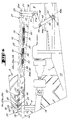
- the cutting machine (1) as shown in Figures 1 to 5 is similar to the cutting machine described in document FR 96 03122. For further details, if necessary, refer to the text of said document.
- the cutting machine (1) is intended for cutting and / or grinding plants. It has a structure coupling (2) provided with two lower coupling points (3, 4) and a point upper hitch (5) by means of which said cutting machine (1) is linked to a motor vehicle (6).
- a suspension arm is linked to the coupling structure (2) (8) by means of a first articulation (9) with a longitudinal axis (9a) at least substantially vertical.
- a cutting mechanism (10) by means of a second axis articulation (12) longitudinal (12a) at least substantially horizontal and at least substantially parallel to the feed direction (13) when said cutting mechanism (10) is in the working position as shown in Figures 1 and 2.
- an operating means (14) comprising a jack. hydraulic (15) intended to pivot the suspension arm (8) and the section (10) from the working position to the transport position and vice versa, around the longitudinal axis (9a) of the first articulation (9).
- the cutting machine (1) is also provided with a transmission device (16) intended to drive the cutting mechanism (10), said device transmission (16) being itself driven by the motor vehicle (6).
- the cutting machine (1) comprises a device lock (18).
- This locking device (18) allows, in the position of transport, to lock the pivoting of the cutting mechanism (10) around the axis longitudinal (12a) of the second articulation (12) and to authorize said pivoting in working position.
- the locking device (18) comprises a connecting member (19) consisting, according to the example shown, of a rod (20) extending substantially parallel to the suspension arm (8) and above this one.
- this rod (20) is rigid and is linked to one (21) from its ends (21, 22) to a lever mechanism (23) by means of a third articulation (25) comprising at least one geometric axis (25a) substantially parallel to the longitudinal axis (12a) of the second articulation (12).
- the third joint (25) is a joint spherical to avoid excessive detrimental play in said joint.
- the lever mechanism (23) is additionally linked to the cutting mechanism (10). This lever mechanism (23) will be described in more detail later.
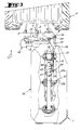
- the rod (20) is linked to the coupling structure (2) by a connecting means (26) located higher than the first articulation (9).
- the connecting means (26) has a fourth articulation (27) having a geometric axis (27a) directed upwards.
- the axis geometric (27a) of the fourth articulation (27) is at least substantially coincident with the longitudinal axis (9a) of the first articulation (9).
- the connecting means (26) also includes a pin pin (28) longitudinal (28a) merged with the geometric axis (27a) of the fourth articulation (27).
- This pin (28) is linked to the rod (20) and extends through a guide device (29) linked to the coupling structure (2).
- this guide device (29) is formed by a support (30) fixed to the coupling structure (2), in which a groove (32) is provided.
- This groove (32) extends transversely to the direction of advance to work (13) and is at least substantially straight. More precisely, the longitudinal axis (32a) of the groove (32) extends at least substantially orthogonally to the direction of advance at work (13) and at least substantially horizontally above the first articulation (9). It will also be noted that the longitudinal axis (32a) of the groove (32) cuts at least substantially orthogonally the longitudinal axis (9a) of the first articulation (9).
- the other end (22) of the rod (20) has two wings (33, 34) between which extends the support (30) of the guide device (29).
- the pin (28) extends from right through through the two wings (33, 34) and through the groove (32) provided in the support (30).
- the pin (28) is cylindrical and the groove (32) is an oblong hole (35) longitudinal axis (35a) coincides with the longitudinal axis (32a) of the groove (32).
- the pin (28) and the oblong hole (35) are arranged so that, in position working, said pin (28) can move in the following oblong hole (35) the longitudinal axis (35a) and, when placing in the transport position, said pin (28) can pivot around its longitudinal axis (28a).
- the lever mechanism (23), to which the end (21) of the rod (20) is linked by means of the third articulation (25), is implanted between the section (10) and the suspension arm (8).
- This lever mechanism (23) transforms the pivoting of the cutting mechanism (10) about the longitudinal axis (12a) of the second articulation (12), in a substantially rectilinear, horizontal displacement and transverse to the direction of advance to work (13) of the rod (20).
- the lever mechanism (23) comprises a pivoting lever (36) with two branches (37, 38) and a connecting rod (40).
- the pivoting lever (36) is linked in its middle part to the suspension arm (8) by means of a fifth articulation (41) with a longitudinal axis (4 la) at least substantially parallel to the longitudinal axis (12a) of the second articulation (12).
- the first branch (37) of the pivoting lever (36) is linked to the end (21) of the rod (20) by means of the third articulation (25) described above, then that the second branch (38) of the pivoting lever (36) is linked to one (42) of ends (42, 43) of the connecting rod (40) by means of a sixth articulation (44) with a longitudinal axis (44a) at least substantially parallel to the longitudinal axis (12a) of the second joint (12).
- the third joint (25) is located in the same vertical plane directed in the direction of advance to work (13) than the fifth articulation (41).
- Said third articulation (25) is located above the fifth joint (41), while the sixth joint (44) is located somewhat below said fifth joint (41).
- Said sixth articulation (44) is also located in a vertical plane directed on the one hand following the direction of advance to work (13) and located on the other hand between the fifth joint (41) and the first joint (9).
- the connecting rod (40) is located between the pivoting lever (36) and the cut (10).
- the connecting rod (40) is linked to the other (43) of its ends (42, 43) to the cutting mechanism (10) by means of a seventh articulation (45) of axis longitudinal (45a) at least substantially parallel to the longitudinal axis (12a) of the second articulation (12).
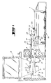
- This seventh articulation (45) is located, such that visible in FIG. 4, in the normal working position, on the one hand in a plane horizontal implanted below the sixth joint (44) and on the other hand in a vertical plane implanted between said sixth articulation (44) and the fifth articulation (41).
- the seventh joint (45) is a joint elastic which absorbs, in the working position as in the transport position, the different shocks to which the locking device (18) is subjected.
- each stop (47, 48) is located in the vicinity of the connecting means (26). Specifically, each stop (47, 48) is formed by one end (49, 50) of the oblong hole (35).
- the cutting machine (1) comprises a stabilizing device (51) intended to recall the mechanism of cutting (10) in a predetermined position when said cutting mechanism (10) is in the working position.
- the device stabilizer (51) is arranged with the locking device (18) and the position predetermined is the normal working position, i.e. where the mechanism cutting (10) extends at least substantially horizontally.
- the stabilizing device (51) comprises two elastic elements (53, 53 ') each located between the rod (20) and the suspension arm (8).
- each elastic element (53, 53 ') is composed of a tension spring (54) with longitudinal axis (54a) acting in opposite directions.
- each tension spring (54) is linked at one of its ends to a common leg (55) fixed on the suspension arm (8) and, at the other end to a respective clip (56, 57) fixed on the rod (20).
- each tension spring (54) is tensioned so as to provide some initial stability to the cutting mechanism (10) especially in swath position (cutting mechanism (10) extending over the cut or cut plants for headland maneuvers).
- the longitudinal axes (54a) of the tension springs (54) are and that the line of action (58) of said tension springs (54) is, according to a rear view, in the working position, at least substantially parallel to a straight (59) passing through the third and fourth articulation (25, 27) and, according to a top view, at least substantially coincident with said straight line (59).
- tension springs (54) allows, in the position of transport, to bring the pin (28) at least substantially in the middle of the hole oblong (35) to ensure perfect stability of the cutting mechanism (10).
- the cutting machine (1) operates from the as follows: when the cutting machine (1) is in the position transport, as shown in Figures 3 and 5, the cutting mechanism (10) extends above the ground (S) and with the suspension arm (8), at least substantially parallel to the direction of advance to work (13), behind the coupling structure (2).
- the longitudinal axis (20a) of the rod (20) extends, in a top view, substantially orthogonally to the axis longitudinal (35a) of the oblong hole (35), which allows no displacement of said rod (20) relative to the coupling structure (2) and which has the effect of lock the second joint (12) and fix the cutting mechanism (10) to the suspension arm (8).
- the operator When the operator wishes to bring the cutting machine (1) from the position transport in the working position, it actuates the operating means (14), this which has the effect of pivoting the cutting mechanism (10) and the suspension (8) around the longitudinal axis (9a) of the first articulation (9) in the working position in which they extend substantially orthogonally to the direction of advance to work (13).
- the rod (20) pivots about the geometric axis (27a) of the fourth articulation (27) until it extends substantially orthogonally to the direction ahead of work (13).
- the longitudinal axis (20a) of the rod (20) is substantially coincident with the longitudinal axis (35a) of the oblong hole (35), which allows the pin (28) to move in said oblong hole (35).
- the operator lowers the cutting machine (1) so that the cutting mechanism (10) on the ground (S).
- the cutting machine (1) is in position of work.
- the operator actuates the transmission device (16) from the motor vehicle (6) in order to drive said cutting mechanism (10).
- the cutting machine (1) is moved in a field covered with plants to be cut using the motor vehicle (6).
- the cutting mechanism (10) can easily adapt to the relief of the ground (S) by pivoting in particular around the axis longitudinal (12a) of the second articulation (12).
- the connecting rod (40) the cutting mechanism (10) acts on the pivoting lever (36), which pivots around of the longitudinal axis (41a) of the fifth articulation (41) which has the effect of move the rod (20) in a vertical plane containing the longitudinal axis (35a) of the oblong hole (35).
- the pin (28) is moves longitudinally in the oblong hole (35) within the limits authorized by these ends (49, 50).
- the operator When the operator wishes to bring the cutting machine (1) from the position working in the transport position, it cuts the drive of the mechanism cut (10), raise the latter above the ground (S) and activate the means of maneuver (14) to pivot said cutting mechanism (10) and the arm of suspension (8) around the longitudinal axis (9a) of the first articulation (9) to the transport position.
- the intensity of the action provided by the stabilizing device (51) is adjustable so as to be able adapt the predetermined position of the cutting mechanism according to the mass distribution of it.
- it can for example be provided for move the fasteners (56, 57) along the rod (20).
- a stabilizing device equipped with compression springs it is possible to have two springs of compression one opposite the other, each coming on the one hand by pressing on a common support fixed on the suspension arm (8) and on the other hand on a support respective integral with the rod (20). It can also be provided that the axis longitudinal of a compression spring is coincident with the longitudinal axis of the other compression spring and that the longitudinal axes of said springs are coincident with the longitudinal axis (20a) of the rod (20).
- the cutting mechanism (10) will keep the predetermined working position in transport position.
- the cutting mechanism (10) will pivot around the axis longitudinal (12a) of the second articulation (12) when the position of work or transport of the cutting machine (1), that is to say that said cutting mechanism (10) will occupy in the transport position, a relative position relative to the suspension arm (8) different from that of the working position.
Landscapes
- Life Sciences & Earth Sciences (AREA)
- Environmental Sciences (AREA)
- Harvester Elements (AREA)
- Agricultural Machines (AREA)
- Harvesting Machines For Specific Crops (AREA)
- Confectionery (AREA)
- Control And Other Processes For Unpacking Of Materials (AREA)
- Apparatuses For Bulk Treatment Of Fruits And Vegetables And Apparatuses For Preparing Feeds (AREA)
Description
- une structure d'attelage destinée à être liée à un véhicule moteur ;
- un mécanisme de coupe s'étendant, lors du travail, transversalement à la direction d'avance au travail (position de travail) et, lors du transport, au moins sensiblement suivant la direction d'avance au travail (position de transport) ;
- un bras de suspension lié d'une part à la structure d'attelage au moyen d'une première articulation d'axe longitudinal dirigé vers le haut et d'autre part au mécanisme de coupe au moyen d'une deuxième articulation d'axe longitudinal dirigé au moins sensiblement suivant la direction d'avance au travail lorsque ledit mécanisme de coupe est dans la position de travail ;
- un dispositif de verrouillage permettant, en position de transport, de verrouiller le pivotement du mécanisme de coupe autour de l'axe longitudinal de la deuxième articulation, et comportant un organe de liaison lié d'une part au mécanisme de coupe et d'autre part à la structure d'attelage.
- permettant, en position de travail, un déplacement de l'organe de liaison par rapport à la structure d'attelage, et
- interdisant, en position de transport, un déplacement de l'organe de liaison par rapport à la structure d'attelage.
- l'organe de liaison est lié à la structure d'attelage à l'aide du moyen de
liaison lequel:
- permet, en position de travail un déplacement de l'organe de liaison par rapport à la structure d'attelage transversalement à la direction d'avance au travail ; et
- interdit, en position de transport, un déplacement de l'organe de liaison par rapport à la structure d'attelage suivant la direction d'avance au travail.
- le moyen de liaison liant l'organe de liaison à la structure d'attelage comporte une quatrième articulation présentant un axe géométrique dirigé vers le haut ;
- en position normale de travail (mécanisme de coupe s'étendant horizontalement), l'axe géométrique de la quatrième articulation est au moins sensiblement confondu avec l'axe longitudinal de la première articulation ; un tel agencement permet de pivoter le mécanisme de coupe et le bras de suspension de la position de travail dans la position de transport ou inversement, autour de l'axe longitudinal de la première articulation sans varier la position relative de l'organe de liaison par rapport au bras de suspension et également sans varier la position relative du mécanisme de coupe par rapport audit bras de suspension ; un tel agencement permet notamment de conserver une position sensiblement horizontale du mécanisme de coupe dans la position de transport ce qui présente l'avantage, lors du transport de la machine de coupe, de conserver sensiblement la même garde au sol dans la position andain (mécanisme de coupe s'étendant transversalement à la direction d'avance au travail et au-dessus du sol);
- le moyen de liaison liant l'organe de liaison à la structure d'attelage comporte un tourillon lié à l'organe de liaison et s'étendant au travers d'un dispositif de guidage lié à la structure d'attelage ;
- le dispositif de guidage comporte une rainure s'étendant transversalement à la direction d'avance au travail ;
- la rainure est au moins sensiblement rectiligne ;
- l'axe longitudinal de la rainure s'étend au moins sensiblement orthogonalement à la direction d'avance au travail et au moins sensiblement horizontalement ; un tel positionnement de la rainure permet, en position de travail, à l'organe de liaison de se déplacer transversalement à la direction d'avance au travail et interdit, en position de transport, audit organe de liaison un déplacement représentatif ;
- l'axe longitudinal de la rainure coupe l'axe longitudinal de la première articulation ;
- l'axe longitudinal de la rainure coupe au moins sensiblement orthogonalement l'axe longitudinal de la première articulation ;
- le pivotement du mécanisme de coupe autour de l'axe longitudinal de la deuxième articulation est limité dans chaque sens par une butée ;
- les butées sont implantées dans le voisinage du moyen de liaison liant l'organe de liaison à la structure d'attelage ;
- les butées sont formées par les deux extrémités de la rainure ;
- il est prévu un mécanisme à levier implanté entre le mécanisme de coupe et le bras de suspension, l'organe de liaison étant lié audit mécanisme à levier ;
- le mécanisme à levier comporte un levier pivotant à deux branches :
- qui est lié, dans sa partie médiane au bras de suspension au moyen d'une cinquième articulation d'axe longitudinal au moins sensiblement parallèle à l'axe longitudinal de la deuxième articulation ;
- dont la première branche est liée à l'organe de liaison au moyen de la troisième articulation ; et
- dont la deuxième branche est liée au mécanisme de coupe ; un tel agencement permet de transformer le pivotement du mécanisme de coupe autour de l'axe longitudinal de la deuxième articulation en un mouvement sensiblement rectiligne de l'organe de liaison ;
- le mécanisme à levier comporte en sus une bielle implantée entre le levier pivotant et le mécanisme de coupe, ladite bielle étant liée d'une part au levier pivotant au moyen d'une sixième articulation et d'autre part au mécanisme de coupe au moyen d'une septième articulation, les axes longitudinaux desdites sixième et septième articulations étant au moins sensiblement parallèles à l'axe longitudinal de la deuxième articulation ;
- la septième articulation est une articulation élastique ;
- la machine de coupe de végétaux comporte un dispositif stabilisateur destiné à rappeler le mécanisme de coupe dans une position prédéterminée lorsque ledit mécanisme de coupe se trouve en position de travail ; un tel dispositif stabilisateur permet en sus, lors des manoeuvres en bout de parcelle, lorsque le mécanisme de coupe est suspendu transversalement à la direction d'avance au travail au-dessus du sol au moyen du bras de suspension, de maintenir ledit mécanisme de coupe dans la position prédéterminée ;
- la position prédéterminée est la position normale de travail, c'est-à-dire celle où le mécanisme de coupe s'étend au moins sensiblement horizontalement ;
- le dispositif stabilisateur comporte deux éléments élastiques agissant dans des sens contraires;
- chaque élément élastique est implanté entre l'organe de liaison et le bras de suspension ;
- l'intensité de l'action fournie par le dispositif stabilisateur est réglable ;
- l'organe de liaison s'étend au-dessus du bras de suspension ; une telle position dudit organe de liaison permet avantageusement de le mettre à l'abri des végétaux pour ne pas compromettre le bon fonctionnement du dispositif de verrouillage ;
- l'organe de liaison est constitué d'une tringle s'étendant au moins sensiblement parallèlement au bras de suspension.
- la figure 1 représente, en position de travail, une machine de coupe selon l'invention vue de l'arrière et liée à un véhicule moteur ;
- la figure 2 représente la machine de coupe de la figure 1, vue de dessus ;
- la figure 3 représente la machine de coupe de la figure 1, en position de transport selon une vue de dessus ;
- la figure 4 représente un agrandissement partiel de la figure 1 ;
- la figure 5 représente un agrandissement partiel de la figure 3.
- permet, en position de travail, un déplacement de ladite tringle (20) par rapport à la structure d'attelage (2) transversalement à la direction d'avance au travail (13), et
- interdit, en position de transport, un déplacement de ladite tringle (20) par rapport à la structure d'attelage (2) suivant la direction d'avance au travail (13).
Claims (24)
- Machine de coupe de végétaux comportant:caractérisée en ce que l'organe de liaison (19) est lié au mécanisme de coupe (10) au moyen d'une troisième articulation (25) présentant un axe géométrique (25a) au moins sensiblement parallèle à l'axe longitudinal (12a) de la deuxième articulation (12) et, qu'il est prévu un moyen de liaison (26) solidaire de la structure d'attelage (2):une structure d'attelage (2) destinée à être liée à un véhicule moteur (6);un mécanisme de coupe (10) s'étendant, lors du travail, transversalement à la direction d'avance au travail (13) (position de travail) et, lors du transport, au moins sensiblement suivant la direction d'avance au travail (13) (position de transport) ;un bras de suspension (8) lié d'une part à la structure d'attelage (2) au moyen d'une première articulation (9) d'axe longitudinal (9a) dirigé vers le haut et d'autre part au mécanisme de coupe (10) au moyen d'une deuxième articulation (12) d'axe longitudinal (12a) dirigé au moins sensiblement suivant la direction d'avance au travail (13) lorsque ledit mécanisme de coupe (10) est dans la position de travail ;un dispositif de verrouillage (18) permettant, en position de transport, de verrouiller le pivotement du mécanisme de coupe (10) autour de l'axe longitudinal (12a) de la deuxième articulation (12), et comportant un organe de liaison (19) lié d'une part au mécanisme de coupe (10) et d'autre part à la structure d'attelage (2),permettant, en position de travail, un déplacement de l'organe de liaison (19) par rapport à la structure d'attelage (2), etinterdisant, en position de transport, un déplacement de l'organe de liaison (19) par rapport à la structure d'attelage (2).
- Machine de coupe de végétaux selon la revendication 1, caractérisée en ce que l'organe de liaison (19) est lié à la structure d'attelage (2) à l'aide du moyen de liaison (26) lequel :permet, en position de travail, un déplacement de l'organe de liaison (19) par rapport à la structure d'attelage (2) transversalement à la direction d'avance au travail (13), etinterdit, en position de transport, un déplacement de l'organe de liaison (19) par rapport à la structure d'attelage (2) suivant la direction d'avance au travail (13).
- Machine de coupe de végétaux selon la revendication 1 ou 2, caractérisée en ce que le moyen de liaison (26) liant l'organe de liaison (19) à la structure d'attelage (2) comporte une quatrième articulation (27) présentant un axe géométrique (27a) dirigé vers le haut.
- Machine de coupe de végétaux selon la revendication 3, caractérisée en ce que, en position normale de travail (mécanisme de coupe (10) s'étendant horizontalement), l'axe géométrique (27a) de la quatrième articulation (27) est au moins sensiblement confondu avec l'axe longitudinal (9a) de la première articulation (9).
- Machine de coupe de végétaux selon la revendication 3 ou 4, caractérisée en ce que le moyen de liaison (26) liant l'organe de liaison (19) à la structure d'attelage (2) comporte un tourillon (28) lié à l'organe de liaison (19) et s'étendant au travers d'un dispositif de guidage (29) lié à la structure d'attelage (2).
- Machine de coupe de végétaux selon la revendication 5, caractérisée en ce que le dispositif de guidage (29) comporte une rainure (32) s'étendant transversalement à la direction d'avance au travail (13).
- Machine de coupe de végétaux selon la revendication 6, caractérisée en ce que la rainure (32) est au moins sensiblement rectiligne.
- Machine de coupe de végétaux selon la revendication 7, caractérisée en ce que l'axe longitudinal (32a) de la rainure (32) s'étend au moins sensiblement orthogonalement à la direction d'avance au travail (13) et au moins sensiblement horizontalement.
- Machine de coupe de végétaux selon la revendication 8, caractérisée en ce que l'axe longitudinal (32a) de la rainure (32) coupe l'axe longitudinal (9a) de la première articulation (9).
- Machine de coupe de végétaux selon la revendication 9, caractérisée en ce que l'axe longitudinal (32a) de la rainure (32) coupe au moins sensiblement orthogonalement l'axe longitudinal (9a) de la première articulation (9).
- Machine de coupe de végétaux selon l'une quelconque des revendications 1 à 10, caractérisée en ce que le pivotement du mécanisme de coupe (10) autour de l'axe longitudinal (12a) de la deuxième articulation (12) est limité dans chaque sens par une butée (47, 48).
- Machine de coupe de végétaux selon la revendication 11, caractérisée en ce que les butées (47, 48) sont implantées dans le voisinage du moyen de liaison (26) liant l'organe de liaison (19) à la structure d'attelage (2).
- Machine de coupe de végétaux selon la revendication 12 dans sa dépendance à la revendication 6, caractérisée en ce que les butées (47, 48) sont formées par les deux extrémités (49, 50) de la rainure (32).
- Machine de coupe de végétaux selon l'une quelconque des revendications 1 à 13, caractérisée en ce qu'il est prévu un mécanisme à levier (23) implanté entre le mécanisme de coupe (10) et le bras de suspension (8), l'organe de liaison (19) étant lié audit mécanisme à levier (23).
- Machine de coupe de végétaux selon la revendication 14, caractérisée en ce que le mécanisme à levier (23) comporte un levier pivotant (36) à deux branches (37, 38):qui est lié, dans sa partie médiane, au bras de suspension (8) au moyen d'une cinquième articulation (41) d'axe longitudinal (41a) au moins sensiblement parallèle à l'axe longitudinal (12a) de la deuxième articulation (12);dont la première branche (37) est liée à l'organe de liaison (19) au moyen de la troisième articulation (25); etdont la deuxième branche (38) est liée au mécanisme de coupe (10).
- Machine de coupe de végétaux selon la revendication 15, caractérisée en ce que le mécanisme à levier (23) comporte en sus une bielle (40) implantée entre le levier pivotant (36) et le mécanisme de coupe (10), ladite bielle (40) étant liée d'une part au levier pivotant (36) au moyen d'une sixième articulation (44) d'axe longitudinal (44a) et d'autre part au mécanisme de coupe (10) au moyen d'une septième articulation (45) d'axe longitudinal (45a), lesdits axes longitudinaux (44a, 45a) étant au moins sensiblement parallèles à l'axe longitudinal (12a) de la deuxième articulation (12).
- Machine de coupe de végétaux selon la revendication 16, caractérisée en ce que la septième articulation (45) est une articulation élastique.
- Machine de coupe de végétaux selon l'une quelconque des revendications 1 à 17, caractérisée en ce qu'elle comporte un dispositif stabilisateur (51) destiné à rappeler le mécanisme de coupe (10) dans une position prédéterminée, lorsque ledit mécanisme de coupe (10) se trouve en position de travail.
- Machine de coupe de végétaux selon la revendication 18, caractérisée en ce que ladite position prédéterminée est la position normale de travail, c'est-à-dire celle où le mécanisme de coupe (10) s'étend au moins sensiblement horizontalement.
- Machine de coupe de végétaux selon la revendication 18 ou 19, caractérisée en ce que le dispositif stabilisateur (51) comporte deux éléments élastiques (53, 53') agissant dans des sens contraires.
- Machine de coupe de végétaux selon la revendication 20, caractérisée en ce que chaque élément élastique (53, 53') est implanté entre l'organe de liaison (19) et le bras de suspension (8).
- Machine de coupe de végétaux selon l'une quelconque des revendications 18 à 21, caractérisée en ce que l'intensité de l'action fournie par le dispositif stabilisateur (51) est réglable.
- Machine de coupe de végétaux selon l'une quelconque des revendications 1 à 22, caractérisée en ce que l'organe de liaison (19) s'étend au-dessus du bras de suspension (8).
- Machine de coupe de végétaux selon l'une quelconque des revendications 1 à 23, caractérisée en ce que l'organe de liaison (19) est constitué d'une tringle (20) s'étendant au moins sensiblement parallèlement au bras de suspension (8).
Applications Claiming Priority (2)
| Application Number | Priority Date | Filing Date | Title |
|---|---|---|---|
| FR9606697 | 1996-05-28 | ||
| FR9606697A FR2749127B1 (fr) | 1996-05-28 | 1996-05-28 | Machine de coupe de vegetaux, destinee a etre attelee a un vehicule moteur, avec un dispositif de verrouillage du mecanisme de coupe |
Publications (2)
| Publication Number | Publication Date |
|---|---|
| EP0809928A1 EP0809928A1 (fr) | 1997-12-03 |
| EP0809928B1 true EP0809928B1 (fr) | 2002-08-07 |
Family
ID=9492574
Family Applications (1)
| Application Number | Title | Priority Date | Filing Date |
|---|---|---|---|
| EP97440046A Expired - Lifetime EP0809928B1 (fr) | 1996-05-28 | 1997-05-22 | Machine de coupe |
Country Status (6)
| Country | Link |
|---|---|
| US (1) | US5901537A (fr) |
| EP (1) | EP0809928B1 (fr) |
| AT (1) | ATE221718T1 (fr) |
| DE (1) | DE69714513T2 (fr) |
| DK (1) | DK0809928T3 (fr) |
| FR (1) | FR2749127B1 (fr) |
Families Citing this family (25)
| Publication number | Priority date | Publication date | Assignee | Title |
|---|---|---|---|---|
| FR2784003B1 (fr) | 1998-10-02 | 2000-12-29 | Kuhn Sa | Machine agricole comportant un timon pivotable et des organes de transmission comprenant un accouplement a joints universels |
| FR2786977B1 (fr) | 1998-12-14 | 2001-02-16 | Kuhn Sa | Faucheuse comportant un dispositif centralise de reglage de la force d'allegement exercee sur le mecanisme de recolte |
| FR2774853B1 (fr) | 1999-02-15 | 2001-02-16 | Kuhn Sa | Organe de coupe pour une machine de coupe notamment une faucheuse |
| FR2791224B1 (fr) | 1999-03-24 | 2001-05-25 | Kuhn Sa | Dispositif de coupe d'une machine de coupe, par exemple faucheuse comportant un dispositif d'entrainement du produit coupe |
| FR2792161B1 (fr) | 1999-04-16 | 2001-05-25 | Kuhn Sa | Machine de coupe comportant un dispositif de coupe lie a un chassis au moyen d'un dispositif de liaison ameliore |
| FR2792164B1 (fr) | 1999-04-16 | 2001-05-25 | Kuhn Sa | Dispositif de traitement de fourrage coupe et faucheuse utilisant un tel dispositif de traitement |
| FR2793379B1 (fr) | 1999-05-11 | 2001-07-06 | Kuhn Sa | Dispositif d'adaptation pour barre d'attelage de tracteur |
| FR2794206B1 (fr) | 1999-05-26 | 2001-07-06 | Kuhn Sa | Procede de montage/demontage et de reglage automatique de la tension d'un organe de transmission sans fin - machine agricole utilisant un tel procede |
| FR2794934B1 (fr) | 1999-06-17 | 2001-08-10 | Kuhn Sa | Machine agricole du type faucheuse ou faucheuse- conditionnneuse comportant un organe d'amortissement |
| DE10011730C2 (de) * | 2000-03-10 | 2002-01-31 | Krone Bernhard Gmbh Maschf | Mähmaschine |
| FR2823061B1 (fr) | 2001-04-06 | 2003-09-26 | Kuhn Sa | Machine de recolte avec un dispositif d'entrainement perfectionne |
| FR2823636A1 (fr) | 2001-04-18 | 2002-10-25 | Kuhn Sa | Machine de fenaison, notamment une faucheuse avec un dispositif groupeur d'andains |
| FR2823637A1 (fr) | 2001-04-18 | 2002-10-25 | Kuhn Sa | Faucheuse agricole comportant un mecanisme de regroupement d'andains |
| CA2352993A1 (fr) * | 2001-07-13 | 2003-01-13 | Solarbear Corporation | Vehicule electrique et train de faucheuse a rouleaux |
| FR2881021B1 (fr) | 2005-01-26 | 2007-02-23 | Kuhn Sa Sa | Faucheuse avec dispositif de depliage et de repliage perfectionne |
| US7207166B2 (en) * | 2005-02-02 | 2007-04-24 | Deere & Company | Side-pull mower-conditioner tongue pivotably mounted to platform frame at location inboard of platform gearbox |
| FR2885483B1 (fr) | 2005-05-10 | 2007-06-15 | Kuhn Sa Sa | Faucheuse avec des ensembles de fauche repliables |
| FR2899430B1 (fr) * | 2006-04-11 | 2010-03-19 | Kuhn Sa | Rouleau conditionneur de faucheuse-conditionneuse, procede de fabrication d'un tel rouleau et faucheuse-conditionneuse equipee d'un tel rouleau |
| US7658056B2 (en) * | 2007-10-30 | 2010-02-09 | Vermeer Manufacturing Co. | System for folding an agricultural machine with a floating work tool |
| FR2930866B1 (fr) | 2008-05-06 | 2010-06-04 | Kuhn Sa | Machine de fenaison avec un protecteur central perfectionne |
| CA2815427C (fr) | 2012-04-26 | 2016-06-28 | Macdon Industries Ltd. | Systeme de transport de machine a recolter par traction pourvu d'une plaque de protection d'andains etales |
| US10462964B2 (en) * | 2015-09-16 | 2019-11-05 | Deere & Company | Rear mounted rotating mower assembly |
| GB201900703D0 (en) * | 2019-01-18 | 2019-03-06 | Agco Feucht Gmbh | Improved hay tool |
| CN111496867B (zh) * | 2020-04-24 | 2022-09-09 | 南宁学院 | 一种多芽段种芽蔗种切断机构 |
| GR1009972B (el) * | 2020-09-12 | 2021-04-06 | Κωνσταντινος Ιωαννη Τσουντανης | Μηχανισμος αναρτησης στελεχοκοπτη με δυο παραλληλους οδηγους για την κινηση αρθρωτου υδραυλικου μηχανισμου που κινει τον στελεχοκοπτη σε τεσσερις βαθμους ελευθεριας |
Family Cites Families (20)
| Publication number | Priority date | Publication date | Assignee | Title |
|---|---|---|---|---|
| DE1582356A1 (de) * | 1967-10-13 | 1970-04-30 | Krone Bernhard Gmbh Maschf | Maehmaschine |
| DE2053073C3 (de) * | 1970-10-29 | 1981-01-29 | Maschinenfabriken Bernard Krone Gmbh, 4441 Spelle | Mähmaschine |
| DE2129804A1 (de) * | 1971-06-16 | 1972-12-21 | Krone Bernhard Gmbh Maschf | Maehmaschine |
| DE8413456U1 (de) * | 1984-05-03 | 1984-08-09 | Claas Saulgau GmbH, 7968 Saulgau | Maehwerk |
| DE8803171U1 (de) * | 1988-02-27 | 1988-05-05 | Fella-Werke Gmbh, 8501 Feucht | Mähwerk |
| FR2654896B1 (fr) * | 1989-11-24 | 1992-02-21 | Kuhn Sa | Faucheuse comportant un groupe d'organes de travail s'etendant au travail transversalement a la direction d'avance. |
| FR2654897B1 (fr) * | 1989-11-24 | 1992-03-20 | Kuhn Sa | Faucheuse avec dispositif d'allegement perfectionne. |
| FR2654893B1 (fr) * | 1989-11-24 | 1992-02-21 | Kuhn Sa | Machine agricole avec dispositif de suspension du groupe d'organes de travail perfectionne. |
| FR2668881B1 (fr) * | 1990-11-12 | 1994-05-27 | Kuhn Sa | Machine agricole, en particulier faucheuse, s'adaptant aisement au relief du terrain et comportant un carter pivotant. |
| FR2668880B1 (fr) * | 1990-11-12 | 1995-06-30 | Kuhn Sa | Procede de transformation d'une machine de recolte pour l'amener d'une position de transport dans une position de travail, et machine de recolte. |
| FR2687039B1 (fr) * | 1992-02-12 | 1994-04-29 | Kuhn Sa | Faucheuse avec un dispositif de verrouillage perfectionne. |
| FR2691041B1 (fr) * | 1992-05-14 | 1999-02-26 | Kuhn Sa | Machine de coupe, notamment faucheuse, s'adaptant aisement au relief du sol. |
| FR2691037B1 (fr) * | 1992-05-14 | 1999-02-26 | Kuhn Sa | Machine agricole, notamment faucheuse, avec un dispositif de delestage et de levage perfectionne. |
| FR2696898B1 (fr) * | 1992-10-16 | 1994-12-09 | Kuhn Sa | Faucheuse avec un entraînement perfectionné des rouleaux de traitement. |
| NL9202216A (nl) * | 1992-12-21 | 1994-07-18 | Greenland Geldrop Bv | Maaimachine. |
| FR2712764B1 (fr) * | 1993-11-23 | 1996-02-09 | Kuhn Sa | Machine agricole à timon perfectionné. |
| DK173820B1 (da) * | 1993-11-26 | 2001-11-19 | Freudendahl J Fab As | Ophængt redskab |
| FR2715797B1 (fr) * | 1994-02-08 | 1996-04-12 | Kuhn Sa | Faucheuse rotative avec barre de coupe et structure support. |
| FR2726152B1 (fr) * | 1994-10-28 | 1997-01-24 | Kuhn Sa | Machine agricole destinee a la coupe de vegetaux avec dispositif de protection perfectionne |
| FR2729817B1 (fr) * | 1995-01-27 | 1997-04-11 | Kuhn Sa | Machine de coupe avec dispositif de commande de l'action d'un ressort d'allegement du mecanisme de coupe |
-
1996
- 1996-05-28 FR FR9606697A patent/FR2749127B1/fr not_active Expired - Fee Related
-
1997
- 1997-05-22 AT AT97440046T patent/ATE221718T1/de active
- 1997-05-22 EP EP97440046A patent/EP0809928B1/fr not_active Expired - Lifetime
- 1997-05-22 DE DE69714513T patent/DE69714513T2/de not_active Expired - Lifetime
- 1997-05-22 DK DK97440046T patent/DK0809928T3/da active
- 1997-05-27 US US08/863,430 patent/US5901537A/en not_active Expired - Lifetime
Also Published As
| Publication number | Publication date |
|---|---|
| DE69714513T2 (de) | 2003-06-18 |
| DE69714513D1 (de) | 2002-09-12 |
| EP0809928A1 (fr) | 1997-12-03 |
| FR2749127A1 (fr) | 1997-12-05 |
| US5901537A (en) | 1999-05-11 |
| DK0809928T3 (da) | 2002-11-18 |
| ATE221718T1 (de) | 2002-08-15 |
| FR2749127B1 (fr) | 1998-08-07 |
Similar Documents
| Publication | Publication Date | Title |
|---|---|---|
| EP0809928B1 (fr) | Machine de coupe | |
| EP0356358B1 (fr) | Faucheuse à châssis perfectionné | |
| EP0211785B1 (fr) | Faucheuse | |
| CA2226656C (fr) | Machine agricole de coupe perfectionnee | |
| EP0242311B1 (fr) | Faucheuse rotative avec barre de coupe et structure support | |
| FR2654897A1 (fr) | Faucheuse avec dispositif d'allegement perfectionne. | |
| CA2284379C (fr) | Machine agricole comportant un timon pivotable et des organes de transmission comprenant un accouplement a joints universels | |
| FR2654893A1 (fr) | Machine agricole avec dispositif de suspension du groupe d'organes de travail perfectionne. | |
| EP1055843B1 (fr) | Tendeur de courroie | |
| EP3071008B1 (fr) | Machine agricole, notamment machine pour la recolte de vegetaux, comportant deux unites de travail animees articulees a un meme bras lateral | |
| EP0382666A1 (fr) | Faucheuse avec dispositif de sécurité à déclenchement | |
| EP0511922B1 (fr) | Machine de coupe perfectionnée avec structure d'attelage pivotante | |
| FR2530399A1 (fr) | Vehicule articule, notamment sous forme d'une machine agricole | |
| CA2292263C (fr) | Faucheuse comportant un dispositif centralise de reglage de la force d'allegement exercee sur le mecanisme de recolte | |
| EP1044593B1 (fr) | Faucheuse | |
| EP0839443B1 (fr) | Machine de coupe | |
| EP0064115B1 (fr) | Faucheuse-conditionneuse | |
| EP0804871B1 (fr) | Machine de coupe | |
| EP2959759B1 (fr) | Machine agricole munie d'un dispositif de centrage | |
| EP0554200B1 (fr) | Machine de fenaison comportant un châssis avec des roues porteuses commandées | |
| FR2489080A1 (fr) | Dispositif de raccordement permettant d'atteler des machines agricoles a un vehicule tracteur | |
| FR2912870A1 (fr) | Machine de coupe de vegetaux, notamment broyeur-debroussailleur | |
| EP0801887B1 (fr) | Faucheuse | |
| EP0374052B1 (fr) | Perfectionnement au dispostif de réglage pour charrue | |
| EP0777959A1 (fr) | Taille-bords pour pelouses |
Legal Events
| Date | Code | Title | Description |
|---|---|---|---|
| PUAI | Public reference made under article 153(3) epc to a published international application that has entered the european phase |
Free format text: ORIGINAL CODE: 0009012 |
|
| AK | Designated contracting states |
Kind code of ref document: A1 Designated state(s): AT DE DK FR GB IT NL |
|
| 17P | Request for examination filed |
Effective date: 19980527 |
|
| 17Q | First examination report despatched |
Effective date: 20000803 |
|
| GRAG | Despatch of communication of intention to grant |
Free format text: ORIGINAL CODE: EPIDOS AGRA |
|
| GRAG | Despatch of communication of intention to grant |
Free format text: ORIGINAL CODE: EPIDOS AGRA |
|
| GRAG | Despatch of communication of intention to grant |
Free format text: ORIGINAL CODE: EPIDOS AGRA |
|
| GRAH | Despatch of communication of intention to grant a patent |
Free format text: ORIGINAL CODE: EPIDOS IGRA |
|
| GRAG | Despatch of communication of intention to grant |
Free format text: ORIGINAL CODE: EPIDOS AGRA |
|
| GRAH | Despatch of communication of intention to grant a patent |
Free format text: ORIGINAL CODE: EPIDOS IGRA |
|
| GRAH | Despatch of communication of intention to grant a patent |
Free format text: ORIGINAL CODE: EPIDOS IGRA |
|
| GRAA | (expected) grant |
Free format text: ORIGINAL CODE: 0009210 |
|
| AK | Designated contracting states |
Kind code of ref document: B1 Designated state(s): AT DE DK FR GB IT NL |
|
| REF | Corresponds to: |
Ref document number: 221718 Country of ref document: AT Date of ref document: 20020815 Kind code of ref document: T |
|
| REG | Reference to a national code |
Ref country code: GB Ref legal event code: FG4D Free format text: NOT ENGLISH |
|
| REF | Corresponds to: |
Ref document number: 69714513 Country of ref document: DE Date of ref document: 20020912 |
|
| GBT | Gb: translation of ep patent filed (gb section 77(6)(a)/1977) |
Effective date: 20020919 |
|
| REG | Reference to a national code |
Ref country code: DK Ref legal event code: T3 |
|
| PLBE | No opposition filed within time limit |
Free format text: ORIGINAL CODE: 0009261 |
|
| STAA | Information on the status of an ep patent application or granted ep patent |
Free format text: STATUS: NO OPPOSITION FILED WITHIN TIME LIMIT |
|
| 26N | No opposition filed |
Effective date: 20030508 |
|
| PGFP | Annual fee paid to national office [announced via postgrant information from national office to epo] |
Ref country code: IT Payment date: 20130527 Year of fee payment: 18 |
|
| PGFP | Annual fee paid to national office [announced via postgrant information from national office to epo] |
Ref country code: GB Payment date: 20140425 Year of fee payment: 18 |
|
| PGFP | Annual fee paid to national office [announced via postgrant information from national office to epo] |
Ref country code: DE Payment date: 20140424 Year of fee payment: 18 Ref country code: NL Payment date: 20140423 Year of fee payment: 18 Ref country code: AT Payment date: 20140424 Year of fee payment: 18 |
|
| PGFP | Annual fee paid to national office [announced via postgrant information from national office to epo] |
Ref country code: DK Payment date: 20140423 Year of fee payment: 18 |
|
| PGFP | Annual fee paid to national office [announced via postgrant information from national office to epo] |
Ref country code: FR Payment date: 20140521 Year of fee payment: 18 |
|
| REG | Reference to a national code |
Ref country code: DE Ref legal event code: R119 Ref document number: 69714513 Country of ref document: DE |
|
| REG | Reference to a national code |
Ref country code: DK Ref legal event code: EBP Effective date: 20150531 |
|
| REG | Reference to a national code |
Ref country code: AT Ref legal event code: MM01 Ref document number: 221718 Country of ref document: AT Kind code of ref document: T Effective date: 20150522 |
|
| GBPC | Gb: european patent ceased through non-payment of renewal fee |
Effective date: 20150522 |
|
| PG25 | Lapsed in a contracting state [announced via postgrant information from national office to epo] |
Ref country code: IT Free format text: LAPSE BECAUSE OF NON-PAYMENT OF DUE FEES Effective date: 20150522 |
|
| REG | Reference to a national code |
Ref country code: NL Ref legal event code: MM Effective date: 20150601 |
|
| REG | Reference to a national code |
Ref country code: FR Ref legal event code: ST Effective date: 20160129 |
|
| PG25 | Lapsed in a contracting state [announced via postgrant information from national office to epo] |
Ref country code: AT Free format text: LAPSE BECAUSE OF NON-PAYMENT OF DUE FEES Effective date: 20150522 |
|
| PG25 | Lapsed in a contracting state [announced via postgrant information from national office to epo] |
Ref country code: GB Free format text: LAPSE BECAUSE OF NON-PAYMENT OF DUE FEES Effective date: 20150522 Ref country code: NL Free format text: LAPSE BECAUSE OF NON-PAYMENT OF DUE FEES Effective date: 20150601 Ref country code: DE Free format text: LAPSE BECAUSE OF NON-PAYMENT OF DUE FEES Effective date: 20151201 Ref country code: DK Free format text: LAPSE BECAUSE OF NON-PAYMENT OF DUE FEES Effective date: 20150531 |
|
| PG25 | Lapsed in a contracting state [announced via postgrant information from national office to epo] |
Ref country code: FR Free format text: LAPSE BECAUSE OF NON-PAYMENT OF DUE FEES Effective date: 20150601 |