EP0809727B1 - Ameliorations relatives a des machines a tufter - Google Patents
Ameliorations relatives a des machines a tufter Download PDFInfo
- Publication number
- EP0809727B1 EP0809727B1 EP96905979A EP96905979A EP0809727B1 EP 0809727 B1 EP0809727 B1 EP 0809727B1 EP 96905979 A EP96905979 A EP 96905979A EP 96905979 A EP96905979 A EP 96905979A EP 0809727 B1 EP0809727 B1 EP 0809727B1
- Authority
- EP
- European Patent Office
- Prior art keywords
- yarn
- detector
- machine according
- tufting machine
- needles
- Prior art date
- Legal status (The legal status is an assumption and is not a legal conclusion. Google has not performed a legal analysis and makes no representation as to the accuracy of the status listed.)
- Expired - Lifetime
Links
- 238000009732 tufting Methods 0.000 title claims abstract description 30
- 238000001514 detection method Methods 0.000 claims abstract description 29
- 230000003287 optical effect Effects 0.000 claims abstract description 5
- 239000004744 fabric Substances 0.000 claims description 19
- 238000009958 sewing Methods 0.000 claims description 9
- 238000004519 manufacturing process Methods 0.000 claims description 6
- 230000000007 visual effect Effects 0.000 claims description 2
- 239000000463 material Substances 0.000 abstract description 4
- 230000000246 remedial effect Effects 0.000 description 2
- 230000006866 deterioration Effects 0.000 description 1
- 238000000059 patterning Methods 0.000 description 1
Images
Classifications
-
- D—TEXTILES; PAPER
- D05—SEWING; EMBROIDERING; TUFTING
- D05C—EMBROIDERING; TUFTING
- D05C15/00—Making pile fabrics or articles having similar surface features by inserting loops into a base material
- D05C15/04—Tufting
- D05C15/08—Tufting machines
- D05C15/16—Arrangements or devices for manipulating threads
- D05C15/18—Thread feeding or tensioning arrangements
Definitions
- This invention relates to tufting machines and in particular to an improved yarn feed arrangement for tufting machines.
- a plurality of yarn carrying needles are mounted on needlebars extending transversely across the machine and these needlebars are reciprocated cyclically to penetrate and insert loops of yarn into a backing material moving longitudinally beneath the needles.
- the loops thus formed are seized either by loopers or hooks mounted on a hook bar depending upon whether it is desired to produce loop or cut pile in the material.
- a problem is encountered in relation to machines of the abovementioned type insofar as if the feed of yarn to one or more needles is not correct, for example due to yarn breakage, unthreading of the yarn from the needle or exhaustion of the supply of yarn from which the yarn is fed, it is not normally possible to detect such fault conditions to prevent errors in sewing the tufted fabric and therefore prevent either a reduction in quality of the finished tufted fabric or indeed even the production of commercially useless finished tufted fabric.
- a tufting machine including a yarn feed arrangement for feeding yarn from a supply thereof to the needles of the machine, each of said needles being reciprocable for sewing by needle drive means in accordance with stored instructions said feed arrangement including fault detection means which senses movement of yarn between one or more needles and said supply and produces a signal which is indicative thereof, said signal being compared with a stored instruction to ensure correct sewing in accordance with a desired pattern characterised in that said needles are independently reciprocable and said stored instructions are in said control means and relate to the production of patterns.
- said fault detection means upon detection of a fault, is operable to cause said tufting machine to stop.
- said fault detection means includes a detector placed in a path of said yarn from said supply to each said needle.
- Each detector may be positioned to detect the yarn requirements of one or more needles in the machines. For example, a single detector may detect the yarn requirements for an amount of 10 or 20 needles. Alternatively, a separate detector may be provided to detect the yarn requirements of each needle.
- each said detector provides a signal indicative of the detection of a fault, where detected, or indicative of non-detection of a fault and said detector may be coupled to a display means upon which a suitable display of the indication can be made. More than one detector may be linked to a single display means and in a particularly preferred embodiment, all detectors are linked to a single display means, which display means is operable to provide a display showing the detection or non-detection of a fault indication in yarn feed to each needle of the machine.
- the fault detection means comprises an optical detection means which detects whether yarn passing the detector is moving or stationary which is indicative of whether a needle is sewing yarn loops accurately into the backing cloth.
- the one or more detector means may be linked to a central control means which includes a suitable display, the said control means being operable to receive said fault indication signals from said detection means and provide one or more displays of said indications in a suitable form.
- Said control means may be adapted to store information relating to the production of predetermined patterns.
- Said control means may also be operatively linked to a needlebar of said machine whereby a particular pattern of tufted fabric to be produced can be selected from patterns stored in said control means, and needles of the machine can be operated by said control means to produce a selected pattern in the tufted fabric.
- control means comprises a microprocessor or computer incorporating a visual display unit (VDU).
- VDU visual display unit
- control means may be adapted such that faults must be detected on multiple successive occasions in the feed of yarn to said needle or needles prior to causing said machine to stop to allow remedial action to be taken.
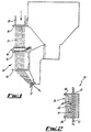
- a yarn feed arrangement 10 for a tufting machine which in use feeds yarn 11 from one or more supplies or creels thereof (not shown) to needles (not shown) of the machine.
- the yarn is fed from the supply down a supply tube 12 and is guided into the region of the needles by a series of fixed yarn guides 13, 14, 16 and 17.
- the detection means 18 is positioned directly in the feed path of the yarn from the supply or creel to the needles and is shown more clearly in Fig. 2.
- the detection means 18 comprises a body 19 having a through bore 21 through which yarn from the supply passes.
- a detector 22 is mounted in a recess 23 in a wall of the body 19, the recess 23 opening out into the through bore 21.
- the detector 22 is connected to control circuitry 24 which can be conveniently mounted on a printed circuit board (PCB) mounted behind the detector 22 and held in position between two rearwardly extending arms 26 of the body 19.
- PCB printed circuit board
- the detector 22 comprises an optical detector, although it will be appreciated that any suitable form of detector can be used as desired or as appropriate.
- the control circuitry can be mounted remote from the detector 22 or body 19, whilst remaining electrically connected thereto.
- the control circuitry 24 is connected to a control computer (not shown) which is able to send signals to the control circuitry 24 and receive signals from the detector 22.
- the signals received from the detector can be displayed on a suitable display (not shown).
- the control computer 15 may also be operable to control operation of the tufting machine in accordance with pattern requirements for the finished tufted fabric and instructions for the production of predetermined patterns are stored in the computer or may be entered by an operator.
- yarn 11 is fed from the supply or creel through the through bore 21 of the detection means 18 and to the needles of the machine. Movement of the yarn through the through bore 21 is detected by the detector 22 and a signal is fed back to the control computer via control circuitry 24 indicating that the yarn is moving or stationary.
- a single detector 22 is used to detect movement of a number of yarns 11, although it should be appreciated that, if desired or appropriate, a number of detectors 22 may be provided, each detecting movement of a number of yarns 11 or alternatively a separate detector 22 may be provided for each yarn 11.
- the signal received from the detector 22 can be displayed on a display which may or may not be associated with the control computer.
- control circuitry 24 or control computer if a signal is received from a detector 22 indicating that a particular yarn 11 is not moving as required, or is moving when not required, the control circuitry 24 or control computer is operable to cease operation of the tufting machine so that any fault can be rectified in order to avoid deterioration in the quality of a finished tufted fabric.
- control computer may be programmed such that the machine will only be shut down upon actuation of multiple successive faults in the yarn feed to the same needle or needles.
- the signal received from the or each detector 22 can be compared with the stored instructions to ensure that a particular needle sews loops in the backing fabric in accordance with the requirements of the particular pattern to be produced at the appropriate time by sensing the movement of yarn caused by the sewing.
- each detector 22 may be identified in a suitable manner such that if a fault occurs, the display may indicate the identification of the detector 22 which has sensed the lack of movement of yarn in order that the location of the fault in the machine can be readily identified.
Landscapes
- Engineering & Computer Science (AREA)
- Chemical & Material Sciences (AREA)
- Materials Engineering (AREA)
- Textile Engineering (AREA)
- Sewing Machines And Sewing (AREA)
- Steam Or Hot-Water Central Heating Systems (AREA)
- Knitting Machines (AREA)
- Filamentary Materials, Packages, And Safety Devices Therefor (AREA)
- Bidet-Like Cleaning Device And Other Flush Toilet Accessories (AREA)
- Separation Using Semi-Permeable Membranes (AREA)
- Air Filters, Heat-Exchange Apparatuses, And Housings Of Air-Conditioning Units (AREA)
Claims (17)
- Machine à tufter comportant un agencement d'alimentation de fil (10) pour alimenter un fil (11) depuis une source de fil jusqu'aux aiguilles de la machine, chacune desdites aiguilles pouvant être animée d'un mouvement alternatif pour coudre par un moyen d'entraínement d'aiguille conformément à des instructions mémorisées, ledit agencement d'alimentation (10) comportant un moyen de détection d'erreur (18) qui détecte le mouvement du fil entre une ou plusieurs aiguilles et ladite source de fil et produit un signal qui indique ce mouvement, ledit signal étant comparé à une instruction mémorisée pour garantir une couture correcte conformément à un motif souhaité, caractérisée en ce que lesdites aiguilles peuvent être indépendamment animées d'un mouvement alternatif et lesdites instructions mémorisées se trouvent dans ledit moyen de commande et concernent la production de motifs.
- Machine à tufter selon la revendication 1, caractérisée en ce que ledit moyen de détection d'erreur (18), s'il détecte une erreur, peut être actionné de manière à faire s'arrêter ladite machine à tufter.
- Machine à tufter selon la revendication 1 ou la revendication 2, caractérisée en ce que ledit moyen de détection d'erreur (18) comprend un détecteur (22) placé sur le trajet dudit fil depuis ladite source de fil jusqu'à chacune desdites aiguilles.
- Machine à tufter selon la revendication 4, caractérisée en ce que chaque détecteur (22) est positionné de manière à détecter les exigences en matière de fil d'une ou de plusieurs aiguilles dans la machine.
- Machine à tufter selon la revendication 4, caractérisée en ce qu'un unique détecteur (22) détecte les exigences en matière de fil de 10 ou de 20 aiguilles.
- Machine à tufter selon la revendication 4, caractérisée en ce qu'un détecteur séparé (22) est prévu pour détecter les exigences en matière de fil de chaque aiguille.
- Machine à tufter selon l'une quelconque des revendications 3 à 6, caractérisée en ce que ledit détecteur (22) fournit un signal indiquant la détection d'une erreur, lorsqu'elle a été détectée, ou indiquant la non détection d'une erreur, dans la source d'alimentation de fil à une aiguille particulière ou à une pluralité d'aiguilles.
- Machine à tufter selon la revendication 7, caractérisée en ce que ledit détecteur (22) est accouplé à un moyen d'affichage sur lequel l'indication d'erreur ou de non erreur peut être affichée de manière appropriée.
- Machine à tufter selon la revendication 8, caractérisée en ce que plus d'un détecteur (22) est relié à un moyen d'affichage unique.
- Machine à tufter selon la revendication 9, caractérisée en ce que tous les détecteurs (22) sont reliés à un moyen d'affichage unique, lequel moyen d'affichage peut être actionné pour fournir un affichage indiquant la détection par un détecteur d'une erreur indicative dans l'alimentation en fil à chaque aiguille de la machine.
- Machine à tufter selon l'une quelconque des revendications 1 à 10, caractérisée en ce que ledit moyen de détection d'erreur (18) comprend un moyen de détecteur optique qui détecte si le fil passant devant le détecteur est en mouvement ou stationnaire, ce qui indique si une aiguille coud des boucles de fil de manière précise dans le tissu de support.
- Machine à tufter selon l'une quelconque des revendications 1 à 11, caractérisée en ce que lesdits un ou plusieurs moyens de détecteur (22) sont reliés à un moyen de commande central (15) qui comporte un affichage approprié, ledit moyen de commande pouvant être actionné pour recevoir les signaux d'indication d'erreur provenant dudit moyen de détection (18) et pour fournir un ou plusieurs affichages desdites indications sous une forme appropriée.
- Machine à tufter selon la revendication 12, caractérisée en ce que ledit moyen de commande (15) est prévu pour mémoriser des informations concernant la production de motifs prédéterminés.
- Machine à tufter selon la revendication 12 ou la revendication 13, caractérisée en ce que ledit moyen de commande (15) est relié fonctionnellement à une barre à aiguilles de ladite machine, un motif particulier de tissu tufté devant être produit pouvant être sélectionné à partir de motifs mémorisés dans ledit moyen de commande, et des aiguilles de la machine pouvant être actionnées par ledit moyen de commande pour produire un motif sélectionné dans le tissu tufté.
- Machine à tufter selon la revendication 14, caractérisée en ce que des signaux envoyés aux aiguilles pour les faire fonctionner afin qu'elles produisent le motif souhaité peuvent être comparés au signal produit par le détecteur pour garantir que le motif sélectionné est produit correctement et précisément par la machine.
- Machine a tufter selon l'une quelconque des revendications 12 à 15, caractérisée en ce que ledit moyen de commande (15) comprend un microprocesseur ou un ordinateur incorporant un écran de visualisation (VDU).
- Machine à tufter selon l'une quelconque des revendications 2 à 16, caractérisée en ce que ledit moyen de détection d'erreur (18) peut être actionné pour faire s'arrêter la machine seulement lorsque de multiples erreurs successives ont été détectées dans la même aiguille ou les mêmes aiguilles.
Applications Claiming Priority (3)
| Application Number | Priority Date | Filing Date | Title |
|---|---|---|---|
| GBGB9503001.1A GB9503001D0 (en) | 1995-02-16 | 1995-02-16 | Improvements in or relating to tufting machines |
| GB9503001 | 1995-02-16 | ||
| PCT/IB1996/000278 WO1996025544A1 (fr) | 1995-02-16 | 1996-02-16 | Ameliorations relatives a des machines a tufter |
Publications (2)
| Publication Number | Publication Date |
|---|---|
| EP0809727A1 EP0809727A1 (fr) | 1997-12-03 |
| EP0809727B1 true EP0809727B1 (fr) | 2003-07-16 |
Family
ID=10769681
Family Applications (1)
| Application Number | Title | Priority Date | Filing Date |
|---|---|---|---|
| EP96905979A Expired - Lifetime EP0809727B1 (fr) | 1995-02-16 | 1996-02-16 | Ameliorations relatives a des machines a tufter |
Country Status (7)
| Country | Link |
|---|---|
| US (1) | US5662054A (fr) |
| EP (1) | EP0809727B1 (fr) |
| JP (1) | JPH11500188A (fr) |
| AT (1) | ATE245218T1 (fr) |
| DE (2) | DE69629105D1 (fr) |
| GB (1) | GB9503001D0 (fr) |
| WO (1) | WO1996025544A1 (fr) |
Families Citing this family (22)
| Publication number | Priority date | Publication date | Assignee | Title |
|---|---|---|---|---|
| US5974991A (en) * | 1996-03-22 | 1999-11-02 | Spencer Wright Industries, Inc. | Controlled needle tofting machine |
| US7096806B2 (en) * | 2002-07-03 | 2006-08-29 | Card-Monroe Corp. | Yarn feed system for tufting machines |
| US6807917B1 (en) | 2002-07-03 | 2004-10-26 | Card-Monroe Corp. | Yarn feed system for tufting machines |
| US6834601B2 (en) * | 2002-07-03 | 2004-12-28 | Card-Monroe Corp. | Yarn feed system for tufting machines |
| US7717051B1 (en) | 2004-08-23 | 2010-05-18 | Card-Monroe Corp. | System and method for control of the backing feed for a tufting machine |
| US7218987B2 (en) * | 2004-12-23 | 2007-05-15 | Wilcom Pty Ltd | Tufting machine |
| US7634326B2 (en) * | 2006-05-23 | 2009-12-15 | Card-Monroe Corp. | System and method for forming tufted patterns |
| WO2009055560A1 (fr) | 2007-10-23 | 2009-04-30 | Card-Monroe Corporation | Système et procédé permettant de contrôler l'alimentation en fil d'une machine à touffeter |
| EP2077348B1 (fr) * | 2008-01-04 | 2011-08-31 | Wilcom Pty. Limited | Machine à touffeter |
| US8141505B2 (en) | 2008-02-15 | 2012-03-27 | Card-Monroe Corp. | Yarn color placement system |
| US8359989B2 (en) | 2008-02-15 | 2013-01-29 | Card-Monroe Corp. | Stitch distribution control system for tufting machines |
| GB2486103B (en) * | 2009-08-25 | 2014-05-07 | Card Monroe Corp | Integrated motor drive system for motor driven yarn feed attachments |
| USD733586S1 (en) * | 2013-12-11 | 2015-07-07 | Eltex Of Sweden Ab | Compact sensor 1-5 |
| US10072368B2 (en) | 2014-06-05 | 2018-09-11 | Card-Monroe Corp. | Yarn feed roll drive system for tufting machine |
| US10233578B2 (en) | 2016-03-17 | 2019-03-19 | Card-Monroe Corp. | Tufting machine and method of tufting |
| US11193225B2 (en) | 2016-03-17 | 2021-12-07 | Card-Monroe Corp. | Tufting machine and method of tufting |
| USD873156S1 (en) * | 2018-07-04 | 2020-01-21 | Eltex Of Sweden Ab | Compact sensor CII |
| US11242216B2 (en) * | 2018-08-28 | 2022-02-08 | Gary M McComas | Yarn tension and breakage sensor system |
| US12286739B2 (en) * | 2018-08-28 | 2025-04-29 | Gary M McComas | Yarn tension and breakage sensor system |
| US11585029B2 (en) | 2021-02-16 | 2023-02-21 | Card-Monroe Corp. | Tufting maching and method of tufting |
| USD1056680S1 (en) | 2021-02-16 | 2025-01-07 | Card-Monroe Corp. | Gauge module |
| BE1031514B1 (nl) * | 2023-04-17 | 2024-11-18 | Vandewiele | Werkwijze voor het bewaken van de spanning van een poolgaren in een tuftmachine en bewakingssysteem |
Family Cites Families (10)
| Publication number | Priority date | Publication date | Assignee | Title |
|---|---|---|---|---|
| US3352267A (en) * | 1965-11-29 | 1967-11-14 | Singer Co | Control circuit useful with sewing machines |
| US3843883A (en) * | 1973-03-08 | 1974-10-22 | Usm Corp | Thread use monitor |
| US4186672A (en) * | 1977-05-23 | 1980-02-05 | Opelika Manufacturing Corp. | Sewing machine monitor |
| US4306231A (en) * | 1979-04-10 | 1981-12-15 | Spencer Wright Industries, Inc. | Yarn detectors |
| DE3147029A1 (de) * | 1981-11-27 | 1983-06-01 | Herforder Teppichfabrik Huchzermeyer & Co Gmbh, 4900 Herford | "vorrichtung zur ueberwachung der fadenspannung" |
| JP2857880B2 (ja) * | 1988-04-27 | 1999-02-17 | 株式会社バルダン | ミシンにおける下糸検知装置 |
| US4970974A (en) * | 1989-11-09 | 1990-11-20 | Spencer Wright Industries, Inc. | Tufting machine broken yarn detector |
| JP3143797B2 (ja) * | 1990-04-13 | 2001-03-07 | 株式会社オーノ | タフテッド柄出方法およびタフテッド機 |
| US5140920A (en) * | 1990-09-07 | 1992-08-25 | The Charles Stark Draper Laboratory, Inc. | Apparatus for detecting skipped stitches |
| TW221065B (en) * | 1991-09-20 | 1994-02-11 | Miyamoto Kk | Broken thread detecting device |
-
1995
- 1995-02-16 GB GBGB9503001.1A patent/GB9503001D0/en active Pending
-
1996
- 1996-01-30 US US08/593,942 patent/US5662054A/en not_active Expired - Fee Related
- 1996-02-16 DE DE69629105T patent/DE69629105D1/de not_active Expired - Lifetime
- 1996-02-16 WO PCT/IB1996/000278 patent/WO1996025544A1/fr not_active Ceased
- 1996-02-16 EP EP96905979A patent/EP0809727B1/fr not_active Expired - Lifetime
- 1996-02-16 AT AT96905979T patent/ATE245218T1/de not_active IP Right Cessation
- 1996-02-16 DE DE0809727T patent/DE809727T1/de active Pending
- 1996-02-16 JP JP8524803A patent/JPH11500188A/ja active Pending
Also Published As
| Publication number | Publication date |
|---|---|
| WO1996025544A1 (fr) | 1996-08-22 |
| JPH11500188A (ja) | 1999-01-06 |
| ATE245218T1 (de) | 2003-08-15 |
| EP0809727A1 (fr) | 1997-12-03 |
| DE809727T1 (de) | 1998-04-09 |
| US5662054A (en) | 1997-09-02 |
| DE69629105D1 (de) | 2003-08-21 |
| GB9503001D0 (en) | 1995-04-05 |
Similar Documents
| Publication | Publication Date | Title |
|---|---|---|
| EP0809727B1 (fr) | Ameliorations relatives a des machines a tufter | |
| CA2348549C (fr) | Matelasseuse pour housse de matelas a aiguille unique et a bobine permettant d'executer des points de chainette et comprenant un systeme de correction de la deviation de l'aiguille | |
| US6173665B1 (en) | Sewing machine control system | |
| JP2021153947A (ja) | 稼働情報取得装置、稼働情報取得方法及び稼働情報収集システム | |
| KR20010049976A (ko) | 재봉틀 | |
| US8776704B2 (en) | Sewing machine | |
| US4078505A (en) | High tension detectors for multi yarn machinery | |
| KR101659930B1 (ko) | 슬릿이 형성된 보빈을 이용한 미싱의 밑실소요량 확인 및 표시 장치 및 방법 | |
| KR101955529B1 (ko) | 테이프 재봉 부착 방법 및 장치, 몸체 세팅 방법 및 장치 | |
| US5718183A (en) | Sewing machine | |
| CN113646477B (zh) | 一种带有集成式纱线输送和控制系统的筒子架 | |
| US4522139A (en) | Tufting machine broken yarn detector | |
| AU653749B2 (en) | Apparatus for detecting skipped stitches | |
| EP0608267B1 (fr) | Procede et dispositif servant a detecter les points sautes dans une machine a coudre a points de chainette | |
| EP3889334A1 (fr) | Dispositif de détermination de défauts | |
| US20090205548A1 (en) | Sewing machine and computer readable medium storing sewing needle status evaluation program | |
| CN216738832U (zh) | 一种具有断线检测功能的缝纫机 | |
| JP3646475B2 (ja) | 2本針ミシン | |
| JP2854879B2 (ja) | ミシンの上糸供給装置 | |
| KR102137518B1 (ko) | 자수기 점프 스티치 판별 방법 | |
| CN120513211A (zh) | 用于监测簇绒机中绒头纱线张力的方法及监测系统 | |
| JP2009090046A (ja) | ミシン | |
| JPH0265899A (ja) | ミシン装置における自動糸切装置 | |
| KR20160066155A (ko) | 기계 자수기의 자수사 단사 감지장치 |
Legal Events
| Date | Code | Title | Description |
|---|---|---|---|
| PUAI | Public reference made under article 153(3) epc to a published international application that has entered the european phase |
Free format text: ORIGINAL CODE: 0009012 |
|
| 17P | Request for examination filed |
Effective date: 19970915 |
|
| AK | Designated contracting states |
Kind code of ref document: A1 Designated state(s): AT BE CH DE DK ES FR GB GR IE IT LI LU MC NL PT SE |
|
| DET | De: translation of patent claims | ||
| 17Q | First examination report despatched |
Effective date: 19980609 |
|
| RAP1 | Party data changed (applicant data changed or rights of an application transferred) |
Owner name: SPENCER WRIGHT INDUSTRIES, INC. |
|
| GRAG | Despatch of communication of intention to grant |
Free format text: ORIGINAL CODE: EPIDOS AGRA |
|
| GRAG | Despatch of communication of intention to grant |
Free format text: ORIGINAL CODE: EPIDOS AGRA |
|
| GRAH | Despatch of communication of intention to grant a patent |
Free format text: ORIGINAL CODE: EPIDOS IGRA |
|
| GRAH | Despatch of communication of intention to grant a patent |
Free format text: ORIGINAL CODE: EPIDOS IGRA |
|
| GRAA | (expected) grant |
Free format text: ORIGINAL CODE: 0009210 |
|
| AK | Designated contracting states |
Designated state(s): AT BE CH DE DK ES FR GB GR IE IT LI LU MC NL PT SE |
|
| PG25 | Lapsed in a contracting state [announced via postgrant information from national office to epo] |
Ref country code: NL Free format text: LAPSE BECAUSE OF FAILURE TO SUBMIT A TRANSLATION OF THE DESCRIPTION OR TO PAY THE FEE WITHIN THE PRESCRIBED TIME-LIMIT Effective date: 20030716 Ref country code: LI Free format text: LAPSE BECAUSE OF FAILURE TO SUBMIT A TRANSLATION OF THE DESCRIPTION OR TO PAY THE FEE WITHIN THE PRESCRIBED TIME-LIMIT Effective date: 20030716 Ref country code: IT Free format text: LAPSE BECAUSE OF FAILURE TO SUBMIT A TRANSLATION OF THE DESCRIPTION OR TO PAY THE FEE WITHIN THE PRE;WARNING: LAPSES OF ITALIAN PATENTS WITH EFFECTIVE DATE BEFORE 2007 MAY HAVE OCCURRED AT ANY TIME BEFORE 2007. THE CORRECT EFFECTIVE DATE MAY BE DIFFERENT FROM THE ONE RECORDED.SCRIBED TIME-LIMIT Effective date: 20030716 Ref country code: FR Free format text: LAPSE BECAUSE OF FAILURE TO SUBMIT A TRANSLATION OF THE DESCRIPTION OR TO PAY THE FEE WITHIN THE PRESCRIBED TIME-LIMIT Effective date: 20030716 Ref country code: CH Free format text: LAPSE BECAUSE OF FAILURE TO SUBMIT A TRANSLATION OF THE DESCRIPTION OR TO PAY THE FEE WITHIN THE PRESCRIBED TIME-LIMIT Effective date: 20030716 Ref country code: BE Free format text: LAPSE BECAUSE OF FAILURE TO SUBMIT A TRANSLATION OF THE DESCRIPTION OR TO PAY THE FEE WITHIN THE PRESCRIBED TIME-LIMIT Effective date: 20030716 Ref country code: AT Free format text: LAPSE BECAUSE OF FAILURE TO SUBMIT A TRANSLATION OF THE DESCRIPTION OR TO PAY THE FEE WITHIN THE PRESCRIBED TIME-LIMIT Effective date: 20030716 |
|
| REG | Reference to a national code |
Ref country code: GB Ref legal event code: FG4D |
|
| REG | Reference to a national code |
Ref country code: CH Ref legal event code: EP |
|
| REG | Reference to a national code |
Ref country code: IE Ref legal event code: FG4D |
|
| REF | Corresponds to: |
Ref document number: 69629105 Country of ref document: DE Date of ref document: 20030821 Kind code of ref document: P |
|
| PG25 | Lapsed in a contracting state [announced via postgrant information from national office to epo] |
Ref country code: SE Free format text: LAPSE BECAUSE OF FAILURE TO SUBMIT A TRANSLATION OF THE DESCRIPTION OR TO PAY THE FEE WITHIN THE PRESCRIBED TIME-LIMIT Effective date: 20031016 Ref country code: GR Free format text: LAPSE BECAUSE OF FAILURE TO SUBMIT A TRANSLATION OF THE DESCRIPTION OR TO PAY THE FEE WITHIN THE PRESCRIBED TIME-LIMIT Effective date: 20031016 Ref country code: DK Free format text: LAPSE BECAUSE OF FAILURE TO SUBMIT A TRANSLATION OF THE DESCRIPTION OR TO PAY THE FEE WITHIN THE PRESCRIBED TIME-LIMIT Effective date: 20031016 |
|
| PG25 | Lapsed in a contracting state [announced via postgrant information from national office to epo] |
Ref country code: DE Free format text: LAPSE BECAUSE OF FAILURE TO SUBMIT A TRANSLATION OF THE DESCRIPTION OR TO PAY THE FEE WITHIN THE PRESCRIBED TIME-LIMIT Effective date: 20031017 |
|
| PG25 | Lapsed in a contracting state [announced via postgrant information from national office to epo] |
Ref country code: ES Free format text: LAPSE BECAUSE OF FAILURE TO SUBMIT A TRANSLATION OF THE DESCRIPTION OR TO PAY THE FEE WITHIN THE PRESCRIBED TIME-LIMIT Effective date: 20031027 |
|
| NLV1 | Nl: lapsed or annulled due to failure to fulfill the requirements of art. 29p and 29m of the patents act | ||
| PG25 | Lapsed in a contracting state [announced via postgrant information from national office to epo] |
Ref country code: PT Free format text: LAPSE BECAUSE OF FAILURE TO SUBMIT A TRANSLATION OF THE DESCRIPTION OR TO PAY THE FEE WITHIN THE PRESCRIBED TIME-LIMIT Effective date: 20031216 |
|
| REG | Reference to a national code |
Ref country code: CH Ref legal event code: PL |
|
| PG25 | Lapsed in a contracting state [announced via postgrant information from national office to epo] |
Ref country code: LU Free format text: LAPSE BECAUSE OF NON-PAYMENT OF DUE FEES Effective date: 20040216 Ref country code: IE Free format text: LAPSE BECAUSE OF NON-PAYMENT OF DUE FEES Effective date: 20040216 |
|
| PG25 | Lapsed in a contracting state [announced via postgrant information from national office to epo] |
Ref country code: MC Free format text: LAPSE BECAUSE OF NON-PAYMENT OF DUE FEES Effective date: 20040228 |
|
| PLBE | No opposition filed within time limit |
Free format text: ORIGINAL CODE: 0009261 |
|
| STAA | Information on the status of an ep patent application or granted ep patent |
Free format text: STATUS: NO OPPOSITION FILED WITHIN TIME LIMIT |
|
| 26N | No opposition filed |
Effective date: 20040419 |
|
| EN | Fr: translation not filed | ||
| REG | Reference to a national code |
Ref country code: IE Ref legal event code: MM4A |
|
| PGFP | Annual fee paid to national office [announced via postgrant information from national office to epo] |
Ref country code: GB Payment date: 20140224 Year of fee payment: 19 |
|
| GBPC | Gb: european patent ceased through non-payment of renewal fee |
Effective date: 20150216 |
|
| PG25 | Lapsed in a contracting state [announced via postgrant information from national office to epo] |
Ref country code: GB Free format text: LAPSE BECAUSE OF NON-PAYMENT OF DUE FEES Effective date: 20150216 |