EP0809470B1 - Gerät zur ultraschallbehandlung von knochen - Google Patents
Gerät zur ultraschallbehandlung von knochen Download PDFInfo
- Publication number
- EP0809470B1 EP0809470B1 EP95911116A EP95911116A EP0809470B1 EP 0809470 B1 EP0809470 B1 EP 0809470B1 EP 95911116 A EP95911116 A EP 95911116A EP 95911116 A EP95911116 A EP 95911116A EP 0809470 B1 EP0809470 B1 EP 0809470B1
- Authority
- EP
- European Patent Office
- Prior art keywords
- head module
- signal generator
- treatment head
- ultrasonic
- fixture
- Prior art date
- Legal status (The legal status is an assumption and is not a legal conclusion. Google has not performed a legal analysis and makes no representation as to the accuracy of the status listed.)
- Expired - Lifetime
Links
- 238000011282 treatment Methods 0.000 title claims abstract description 82
- 210000000988 bone and bone Anatomy 0.000 title description 8
- 208000027418 Wounds and injury Diseases 0.000 claims abstract description 21
- 230000006378 damage Effects 0.000 claims abstract description 21
- 208000014674 injury Diseases 0.000 claims abstract description 21
- 229920003023 plastic Polymers 0.000 claims abstract description 8
- 239000004033 plastic Substances 0.000 claims abstract description 8
- 238000004891 communication Methods 0.000 claims description 17
- 230000003287 optical effect Effects 0.000 claims description 5
- 230000001105 regulatory effect Effects 0.000 claims description 2
- 238000002604 ultrasonography Methods 0.000 abstract description 10
- 230000005284 excitation Effects 0.000 abstract description 5
- 239000000463 material Substances 0.000 abstract description 4
- 206010061363 Skeletal injury Diseases 0.000 description 13
- 238000009210 therapy by ultrasound Methods 0.000 description 11
- 238000010586 diagram Methods 0.000 description 5
- 239000004020 conductor Substances 0.000 description 4
- 230000035876 healing Effects 0.000 description 4
- 238000003384 imaging method Methods 0.000 description 4
- 238000012544 monitoring process Methods 0.000 description 4
- 208000010392 Bone Fractures Diseases 0.000 description 3
- 206010073713 Musculoskeletal injury Diseases 0.000 description 3
- 239000000835 fiber Substances 0.000 description 3
- 238000012986 modification Methods 0.000 description 3
- 230000004048 modification Effects 0.000 description 3
- 238000002560 therapeutic procedure Methods 0.000 description 3
- PXHVJJICTQNCMI-UHFFFAOYSA-N Nickel Chemical compound [Ni] PXHVJJICTQNCMI-UHFFFAOYSA-N 0.000 description 2
- 206010030113 Oedema Diseases 0.000 description 2
- 208000000558 Varicose Ulcer Diseases 0.000 description 2
- 230000001276 controlling effect Effects 0.000 description 2
- 238000000034 method Methods 0.000 description 2
- 230000005855 radiation Effects 0.000 description 2
- OKTJSMMVPCPJKN-UHFFFAOYSA-N Carbon Chemical compound [C] OKTJSMMVPCPJKN-UHFFFAOYSA-N 0.000 description 1
- WHXSMMKQMYFTQS-UHFFFAOYSA-N Lithium Chemical compound [Li] WHXSMMKQMYFTQS-UHFFFAOYSA-N 0.000 description 1
- 208000001132 Osteoporosis Diseases 0.000 description 1
- 206010052428 Wound Diseases 0.000 description 1
- 229920000122 acrylonitrile butadiene styrene Polymers 0.000 description 1
- 239000000853 adhesive Substances 0.000 description 1
- 230000001070 adhesive effect Effects 0.000 description 1
- XAGFODPZIPBFFR-UHFFFAOYSA-N aluminium Chemical compound [Al] XAGFODPZIPBFFR-UHFFFAOYSA-N 0.000 description 1
- 229910052782 aluminium Inorganic materials 0.000 description 1
- 230000005540 biological transmission Effects 0.000 description 1
- 229910052799 carbon Inorganic materials 0.000 description 1
- 239000004035 construction material Substances 0.000 description 1
- 230000008878 coupling Effects 0.000 description 1
- 238000010168 coupling process Methods 0.000 description 1
- 238000005859 coupling reaction Methods 0.000 description 1
- 238000001514 detection method Methods 0.000 description 1
- 230000002542 deteriorative effect Effects 0.000 description 1
- 238000003745 diagnosis Methods 0.000 description 1
- 230000000694 effects Effects 0.000 description 1
- 230000006870 function Effects 0.000 description 1
- 239000004973 liquid crystal related substance Substances 0.000 description 1
- 229910052744 lithium Inorganic materials 0.000 description 1
- 238000002595 magnetic resonance imaging Methods 0.000 description 1
- 239000007769 metal material Substances 0.000 description 1
- 229910052759 nickel Inorganic materials 0.000 description 1
- 230000005298 paramagnetic effect Effects 0.000 description 1
- 229910001220 stainless steel Inorganic materials 0.000 description 1
- 239000010935 stainless steel Substances 0.000 description 1
- 230000008961 swelling Effects 0.000 description 1
- 230000001225 therapeutic effect Effects 0.000 description 1
- 210000001519 tissue Anatomy 0.000 description 1
- 238000012546 transfer Methods 0.000 description 1
- 210000000623 ulna Anatomy 0.000 description 1
- 238000012800 visualization Methods 0.000 description 1
Images


Classifications
-
- A—HUMAN NECESSITIES
- A61—MEDICAL OR VETERINARY SCIENCE; HYGIENE
- A61B—DIAGNOSIS; SURGERY; IDENTIFICATION
- A61B17/00—Surgical instruments, devices or methods
- A61B17/22—Implements for squeezing-off ulcers or the like on inner organs of the body; Implements for scraping-out cavities of body organs, e.g. bones; for invasive removal or destruction of calculus using mechanical vibrations; for removing obstructions in blood vessels, not otherwise provided for
-
- A—HUMAN NECESSITIES
- A61—MEDICAL OR VETERINARY SCIENCE; HYGIENE
- A61N—ELECTROTHERAPY; MAGNETOTHERAPY; RADIATION THERAPY; ULTRASOUND THERAPY
- A61N7/00—Ultrasound therapy
-
- A—HUMAN NECESSITIES
- A61—MEDICAL OR VETERINARY SCIENCE; HYGIENE
- A61B—DIAGNOSIS; SURGERY; IDENTIFICATION
- A61B17/00—Surgical instruments, devices or methods
- A61B2017/00477—Coupling
-
- A—HUMAN NECESSITIES
- A61—MEDICAL OR VETERINARY SCIENCE; HYGIENE
- A61B—DIAGNOSIS; SURGERY; IDENTIFICATION
- A61B17/00—Surgical instruments, devices or methods
- A61B2017/00477—Coupling
- A61B2017/00482—Coupling with a code
Definitions
- the present invention relates to an apparatus for therapeutically treating injuries using ultrasound. More particularly, the present invention relates to an apparatus which utilizes a portable ergonomically constructed signal generator and an ergonomically constructed transducer for treating bone injuries or a variety of musculoskeletal injuries and/or problems.
- Impinging ultrasonic pulses having appropriate parameters, e.g., frequency, pulse repetition, and amplitude, for suitable periods of time and at a proper external location adjacent to a bone injury has been determined to accelerate the natural healing of, for example, bone breaks and fractures.
- ultrasonic therapy may promote healing of bone injuries that would otherwise require prosthetic replacement or leave the patient permanently disabled.
- U.S. Patent No. 4,530,360 to Duarte describes a basic non-invasive therapeutic technique and apparatus for applying ultrasonic pulses from an operative surface placed on the skin at a location adjacent a bone injury.
- the applicator described in the '360 patent has a plastic tube which serves as a grip for the operator, an RF plug attached to the plastic tube for connection to an RF source, and internal cabling connected to an ultrasonic transducer.
- To apply the ultrasound pulses during treatment an operator must manually hold the applicator in place until the treatment is complete. As a result, the patient is, in effect, immobilized during treatment. The longer the treatment period, the more the patient is inconvenienced.
- the '360 patent also describes a range of RF signals for creating the ultrasound, ultrasound power density levels, a range of duration for each ultrasonic pulse, and a range of ultrasonic pulse frequencies.
- U.S. Patent No. 5,003,965 to Talish et al. relates to an ultrasonic body treatment system having a body-applicator unit connected to a remote control unit by sheathed fiber optic lines.
- the signals controlling the duration of ultrasonic pulses and the pulse repetition frequency are generated apart from the body-applicator unit.
- Talish et al. also describes a mounting fixture for attaching the body-applicator unit to a patient so that the operative surface is adjacent the skin location.
- US 5,003,965 discloses an apparatus corresponding to the preamble of claim 1, having an ultrasonic signal generator and signal generator circuitry associated with the operating unit.
- US 5,211,160 discloses an ultrasonic body treatment apparatus comprising an ultrasonic transducer treatment head and a remote control unit coupled to the said ultrasonic transducer treatment head via a flexible cable.
- the operating unit, the ultrasonic signal generator and the transducer treatment head are formed as an unit.
- This known apparatus is still unsatisfactory with respect to handling thereof.
- the displayed data are not easily perceivable, when the apparatus is mounted, for example on a leg of a patient, and no convenient data input is possible.
- the ultrasonic treatment apparatus of the present invention is used for therapeutically treating injuries using ultrasound.
- the apparatus includes an ergonomically constructed ultrasonic transducer treatment head module with an integral signal generator which provides excitation signals for an ultrasonic transducer within the module.
- the portable main operating unit is constructed to fit within a pouch worn by the patient and provides treatment timing control circuitry as well as monitoring circuitry for the proper attachment and operation of the transducer assembly.
- the module is positioned adjacent the area of the injury and excited for a predetermined period of time.
- a safety interlock is provided to insure compliance with the treatment protocol and to prevent inadvertent excitation of the transducer assembly.
- the main operating unit has an internal power source for powering the signal generator circuitry in the transducer treatment head module, a display coupled to said signal generator circuitry to display treatment sequence data, a keypad coupled to said signal generator circuitry to permit user operation and/or entry of data, said signal generator circuitry including a processor, means for generating a pulsed control signal, and a switch coupled to said processor for regulating said pulsed control signal.
- a communication interface may be connected between a communication port and the processor to provide a communication link between the ultrasonic signal generator and an external computer or modem.
- the communication interface is a serial communication interface, however, a parallel interface is also contemplated.
- An alarm is provided to indicate to the user that the treatment time has expired. The alarm is coupled to the processor such that when ultrasonic treatment is completed the processor activates the alarm and terminates ultrasound generation.
- a safety interlock mechanism is provided.
- the transducer treatment head module is configured to interfit with a fixture positioned adjacent the injury.
- the fixture has an aperture configured to receive a portion of the ultrasonic transducer treatment head module.
- At least two bayonet lugs connected to the fixture and extending into the aperture, are electrically connected to form a conductive path therebetween.
- the ultrasonic transducer treatment head module includes at least two slotted lugs having at least a portion thereof extending from an outer surface of the module.
- the slotted lugs are configured to engage at least two bayonet lugs and are fabricated from conductive plastic such that when the slotted lugs engage the bayonet lugs a conductive path is formed between the slotted lugs.
- the processor sends a safety interlock signal to the transducer treatment head module along one conductor and the conductive path between slotted lugs returns the safety interlock signal to the processor along another conductor.
- the processor receives the return safety interlock signal, the transducer can now be excited. This feature insures that the patient correctly complies with the ultrasound protocol and that the actual treatment is accurately recorded.
- the apparatus may be configured as a kit for ultrasonically treating injuries while maintaining patient mobility.
- the kit includes an ultrasonic transducer treatment head module, a fixture configured to be worn by a patient adjacent the injury and configured to receive at least a portion of the ultrasonic transducer treatment head module, an integrated ultrasonic signal generator located in the ultrasonic transducer treatment head module, a main operating unit (MOU) or controller and a pouch constructed to receive the MOU.
- the pouch has a belt and a shoulder strap which can be releasably secured to a patient during treatment thereby providing patient mobility.
- a single or a plurality of transducer treatment head modules can be attached to a single MOU and be selectively controlled thereby.
- the apparatus of the present invention allows ultrasonically treating musculoskeletal injuries and surface injuries such as, for example, open wounds, burns and venous ulcers, while maintaining patient mobility is also provided.
- the location of the injury is determined.
- a fixture is affixed to the patient adjacent the location.
- the fixture is configured to receive at least a portion of an ultrasonic transducer assembly which is releasably secured to the fixture.
- a pouch having the MOU therein is releasably secured to the patient and is connected to the transducer treatment head module.
- the signal generator in the transducer housing is then activated so as to excite an ultrasonic transducer to impinge ultrasonic waves against the injury.
- the MOU has an internal power source.
- the ultrasonic treatment apparatus of the present invention is used for therapeutically treating injuries using ultrasound. Although shown here for the treatment of musculoskeletal injuries, other injuries including venous ulcers are also contemplated.
- the apparatus includes an ergonomically constructed ultrasonic transducer assembly partially fabricated with a conductive plastic material.
- the apparatus also utilizes a portable, ergonomically constructed main operating unit (MOU) which provides control signals for the ultrasonic transducer treatment head module.
- MOU main operating unit
- the portable MOU is constructed to fit within a pouch worn by the patient.
- the transducer treatment head module is positioned adjacent the injured area and excited for a predetermined period of time.
- a safety interlock is provided to prevent inadvertent excitation of the transducer assembly and to insure patient compliance.
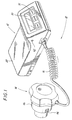
- the ultrasonic treatment apparatus 10 includes an MOU 12 and an ultrasonic transducer treatment head module 14 coupled to the MOU 12 by cable 16.
- the MOU 12 is ergonomically configured and constructed to fit with a pouch 18 which is worn by the patient using belt 19 and shoulder strap 9, as shown in Figs. 2 and 3.
- Cable 16 is preferably a multi-conductor cable capable of transmitting relatively low frequency or optical signals, as well as digital signals. Cable 16 may include coaxial cable or other type of suitable shielded cable. Alternatively, cable 16 may include fiber optic cable for transmitting optical signals.
- MOU 12 includes a housing 20 which is typically constructed in two half-sections joined together by screws, ultrasonic welds or adhesives.
- a printed circuit board 22 is positioned within the housing 20 and coupled to display assembly 24 via cable 26.
- Display assembly 24 includes mounting board 28, display 30 and a keypad 31, shown in Fig. 1.
- Display 30 may be, for example, a liquid crystal type display or an LED type display suitable for displaying text and numerals.
- Battery holder 32 is connected to printed circuit board 22 for portable operation of the real time clock and the ultrasonic treatment head module of the present invention.
- a suitable battery such as a bank of three (3) lithium batteries is positioned in the battery compartment.
- Communication port 34 is affixed to printed circuit board 22 and accessible through channel 36 in housing 20. Communication port 34 is coupled to signal generator circuitry 38 on printed circuit board 22 and provides a communication link, e.g., for serial communications, between the signal generator 12 and an external computer. In this configuration, a physician can download information, such as the number, date, time of day, and/or duration of actual treatments initiated by the patient, stored within signal generator circuitry 38.
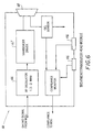
- Fig. 5 illustrates a block diagram of the signal generator circuitry 38 within the signal generator 12 which generates and controls the pulses transferred to the ultrasonic transducer assembly 14.
- signal generator circuitry 38 includes a processor 44 having memory 43 (e.g., RAM and ROM) and stored programs (e.g., system and application) for controlling the operation of the processor, as well as the transducer treatment head module 14.
- Processor 44 is coupled to display 30 and keypad 31 and is configured to receive data from the keypad 31 and to transfer data to the display 30.
- Processor 44 may include a microprocessor, such as the Intel® 80/x86 family of microprocessors, or processor 44 may be a microcontroller having internal memory.
- Communication interface 35 is connected between communication port 34 and processor 44 and is provided to communicate with, for example, an external computer.
- Communication interface 35 may be a serial interface, such as an RS-232 interface, a parallel interface, or a modem.
- Processor 44 is also utilized to control the treatment sequence, i.e., the start time and the stop time of the ultrasonic treatment.
- the processor may be preprogrammed for treatment times and the user (e.g. the physician or patient) selects one of the treatment times via keypad 31, or the processor may be programmed by the user via keypad 31 to set the start and stop sequence. Typical treatment times may range between 1 and 55 minutes, although treatments in the order of 10-20 minutes are typical.
- processor 44 closes switch 60 which permits the modulated signal to pass to cable 16.
- switch 60 is opened and the modulated signal is inhibited from passing to cable 16.
- processor 44 may send an alarm signal to alarm 62 which activates.
- the transducer treatment head module circuitry includes a receiver 66 which receives the signals transferred by signal generator 12 via cable 16. Receiver 66 is connected to transducer driver 67 which excites transducer 68.
- An alternative embodiment of the transducer treatment head module circuitry is shown in Fig. 6A.
- the transducer treatment head module 14 includes an internal battery 69 which supplies power to the internal components of the transducer treatment head module. For example, battery 69 supplies power to signal monitoring circuit 70 and signal driver 71.
- the signal monitoring circuit 70 provides, preferably, a digital output signal 72 which represents the waveform characteristics of the output of transducer driver 67.
- Such characteristics may include, for example, the frequency, pulse repetition frequency, the pulse width and the average output power of the signal driving transducer 68.
- the output signal 72 of signal monitoring circuit 70 is transferred to signal generator 12 via driver 71 and cable 16.
- Fixture interlock 73 which may include switches on the outer surface of the transducer treatment head module, provides power to the internal components of the transducer treatment head module 14 so as to ensure that the transducer treatment head module 14 is properly positioned before the transducer is excited.
- the present invention also envisions a plurality of modules for use with a single MOU.
- the locating ring 80 includes a strap 82 for releasably securing the ring to a patient.
- the strap 82 preferably has two sections 84 and 86 which permit quick fastening and unfastening of the ring 80 on and off the patient.
- the ring 80 is constructed of material that may be seen with a chosen medical visualizing system. Thus, if X-rays are used, the ring 80 is at least partially opaque to X-radiation.
- the ring 80 is at least partially opaque to infra-red radiation, and, if magnetic resonance imaging is used, the ring 80 is at least partially paramagnetic.
- the other materials may be used for the ring which permits detection by medical visualizing or imaging systems.
- the dimensions of the ring 80 are typically a function of the size of the patient, the estimated size and location of the injury, and the type of visualizing system used.
- the diameter of the ring may nominally be 1.5 inches.
- the ring may be a rigid torus of metallic material of cross-sectional diameter nominally .2 inches.
- the visualization system utilized is an ultrasonic imaging system
- the ring 80 may be substantially flexible and planar, so that it may contour to a surface it is placed adjacent to, thereby allowing the scanning or imaging transducer to be moved across the surface and the ring.
- the strap 82 has two sections 84 and 86, each section has one end fastened to the ring 80.
- the two sections 84 and 86 preferably, have hook and loop type fastening assembly, such as VELCRO®, so that they may be fastened together and quickly unfastened. Other quick release fastening techniques are also contemplated.
- Figs. 8 through 12 illustrate locating an injured bone, affixing a fixture configured to maintain the transducer treatment head module adjacent the area of the injured bone, and connecting the ultrasonic transducer assembly to the fixture for treating the injured bone.
- the locator ring 80 is positioned on a cast 88 on, for example, a patient's arm, at a location corresponding to the estimated or approximated location of the injury. This initial position is a preliminary approximation of the external location of the bone injury, and may be based on previously taken X-rays, a physician's diagnosis or the patient's recall of the point of injury.
- An external image, e.g., an X-ray, of the fractured region is taken to include the locating ring 80.
- the initial position of the locating ring 80 with respect to the bone injury is a preliminary approximation, in many instances the initial placement will be sufficiently accurate so that the X-ray will depict the bone injury framed by the ring 80.
- the resulting X-ray image indicates the position of the bone injury relative to the locating ring 80.
- the X-rays are used as a guide to locate and mark 90 the corresponding point on the cast relative to the actual locating ring 80.
- the mark 90 gives an approximate external location on the cast of the bone injury.
- the ring 80 may be centered about the mark 90, another X-ray is taken, and a new mark (not shown) is made on the cast based on the location of the bone fracture relative to the ring on the X-ray. Successive iterations of repositioning the locating ring 80 and X-raying the site will yield even greater accuracy.
- a rectangular template 92 is pressed against the cast 88 and centered on the mark 90 of the external location on the cast 88 of the bone fracture.
- the outline of the inner edges of the template opening is traced on the cast 88, and the traced portion of the cast is removed so that the opening 94 in the cast 88 exposes the skin, as shown in Fig. 10.
- the opening 94 in the cast 88 receives a felt pad 96 having a thickness approximately the same as the thickness of the cast.
- the felt pad 96 also has a cylindrical bore that receives a cylindrical felt pad 98.
- Felt pad 96 is provided to support fixture 102 and to maintain pressure against the skin which helps prevent window edema (swelling) and is substantially equivalent to the pressure exerted by the cast 88 against the skin and is described in more detail below.
- the template 92 and consequently the opening 94 in the cast 88, is smaller than the flange 100 of a fixture 102 for retaining and aligning the ultrasonic transducer assembly 14, so that the flange 100 engages the cast surface surrounding the opening 94 when the fixture is placed over the opening 94.
- the fixture 102 also has a circular aperture 104 and bayonet locking lugs 106.
- Aperture 104 has substantially the same diameter as the cylindrical felt pad 98.
- Fig. 11 shows the fixture 102 positioned over the opening 94 in the cast 88 and the felt pad 96 so that the aperture 104 and the cylindrical felt pad 98 are coaxially aligned.
- the fixture 102 partially compresses the felt pad 96, shown in Fig. 10, against the skin as flange 100 of fixture 102, shown in Fig. 8, engages the cast 88, thereby approximating the pressure of the removed portion of the cast where the felt pad engages the skin.
- a cap 108 for the fixture 102 is shown.
- the cap 108 is provided to maintain pressure on the body tissue exposed in fixture 102 when the ultrasonic treatment is completed.
- the cap 108 has a cylindrical portion 110 that extends into the aperture 104 of the fixture 102.
- the cap 108 has slotted lugs 112 on the cylindrical portion 110 that engage the bayonet lugs 106 in the fixture 102.
- the cylindrical felt pad 98 is positioned in the aperture 104 and the cylindrical portion 110 is inserted into the aperture 104 with the slotted lugs 112 offset from the bayonet lugs 106.
- the cap 108 is pressed against the cylindrical felt pad 98 until the pressure exerted by the cap 108 and cylindrical felt pad 98 against the skin approximates the pressure exerted by the cast 88 against the skin.
- the cylindrical felt pad 98 may also be comprised of substantially planar circular layers that may be removed one layer at a time in order to adjust the thickness of the felt pad and the resulting pressure against the skin.
- This pressure helps to inhibit window edemas.
- the cap 108 is then rotated so that its slotted lugs 112 engage the bayonet lugs 106.
- Fig. 13 is a perspective view illustrating the alignment of the ultrasonic transducer treatment head module 14 with the fixture 102 for ultrasonic treatment of the injured bone.
- the transducer treatment head module projection 114 has slotted lugs 116 that engage the bayonet lugs 106 in the fixture 102. With the cap 108 and cylindrical felt pad 98, shown in Fig. 10, removed, the projection 114 fits into the aperture 104 of the fixture 102 and the bore of the felt pad 96, and is inserted with the slotted lugs 116 offset from the bayonet lugs 106.
- the operative surface 118 of the transducer treatment head module 14 is pressed adjacent the skin and the transducer treatment head module 14 is then rotated so that its slotted lugs 116 engage the bayonet lugs 106.
- the ultrasonic treatment then commences.
- slotted lugs 116 are preferably fabricated from a conductive plastic and the bayonet lugs 106 in fixture 102 are electrically connected, such that when the slotted lugs 116 engage the bayonet lugs 106 an electrical path is completed between at least two of the slotted lugs 116.
- Suitable conductive plastics which may be utilized include conductive ABS plastics with either carbon, stainless steel, nickel or aluminum fibers.
- the operative surface 118 of transducer treatment head module 14 includes a gel sensing element for confirming the presence of ultrasonic conductive material on the operative surface 118.
- This surface 118 is pre-coated with a coupling gel before it is inserted in the fixture 102 and engages the skin.
- the gel may be contained adjacent the operative surface 118 of transducer treatment head module 14 using a gel sack, gel bladder or like container.
Landscapes
- Health & Medical Sciences (AREA)
- Life Sciences & Earth Sciences (AREA)
- Engineering & Computer Science (AREA)
- Biomedical Technology (AREA)
- Nuclear Medicine, Radiotherapy & Molecular Imaging (AREA)
- Animal Behavior & Ethology (AREA)
- General Health & Medical Sciences (AREA)
- Public Health (AREA)
- Veterinary Medicine (AREA)
- Surgery (AREA)
- Radiology & Medical Imaging (AREA)
- Orthopedic Medicine & Surgery (AREA)
- Vascular Medicine (AREA)
- Heart & Thoracic Surgery (AREA)
- Medical Informatics (AREA)
- Molecular Biology (AREA)
- Surgical Instruments (AREA)
- Percussion Or Vibration Massage (AREA)
- Dental Tools And Instruments Or Auxiliary Dental Instruments (AREA)
- Meat, Egg Or Seafood Products (AREA)
Claims (9)
- Eine Vorrichtung zur Ultraschallbehandlung einer Verletzung, bestehend aus:wobei die Hauptbedienungseinheit (12) eine interne Stromversorgung, eine Anzeige (30), die mit der Signalgeneratorschaltung (38) gekoppelt ist, um Behandlungssequenzdaten anzuzeigen, und eine Kleintastatur (31), die mit der Signalgeneratorschaltung gekoppelt ist, um die Kontrolle und Benutzereingabe von Daten zu gestatten, aufweist,einer Hauptbedienungseinheit (12), einem Ultraschallwandler-Behandlungskopfmodul (14), einem Ultraschallsignalgenerator und einer Signalgeneratorschaltung (38),
wobei die Signalgeneratorschaltung (38) einen Prozessor (44), ein Mittel (67) zur Erzeugung eines Impulssignals und einen Schalter, der mit dem Prozessor gekoppelt ist, um das Impulssignal zu regulieren, umfasst, wobei der Signalgenerator so ausgeführt ist, dass er vom Patienten mitgeführt werden kann,
dadurch gekennzeichnet, dass
der Ultraschallsignalgenerator und die Signalgeneratorschaltung im Ultraschallwandler-Behandlungskopfmodul enthalten sind. - Vorrichtung gemäß Anspruch 1, weiterhin bestehend aus einer Tasche (18) zur Aufnahme der Hauptbedienungseinheit (12), wobei die Tasche einen Gürtel (19) und/oder einen Schultergurt (9) umfasst, so dass die Tasche während der Behandlung von einem Patienten getragen werden kann, wodurch Mobilität für den Patienten bereitgestellt wird.
- Vorrichtung gemäß einem der vorhergehenden Ansprüche, weiterhin bestehend aus einem optischen Transmitter, der mit dem Schalter verbunden ist, wobei der optische Transmitter so ausgeführt ist, dass er das Impulssignal in ein optisches Signal umwandelt.
- Vorrichtung gemäß einem der vorhergehenden Ansprüche, weiterhin bestehend aus einer Kommunikationsschnittstelle (35), die zwischen einem Kommunikationsanschluss (34) und dem Prozessor (44) gekoppelt ist, um eine Kommunikationsverbindung zwischen dem Ultraschallsignalgenerator und einem externen Computer/Modem bereitzustellen.
- Vorrichtung gemäß dem vorhergehenden Anspruch, wobei die Kommunikationsschnittstelle (35) eine serielle Kommunikationsschnittstelle ist.
- Vorrichtung gemäß einem der vorhergehenden Ansprüche, weiterhin bestehend aus einem Alarm (62), der mit dem Prozessor (44) verbunden ist, um die genaue Einhaltung eines Behandlungsprotokolls zu prüfen.
- Vorrichtung gemäß einem der vorhergehenden Ansprüche, weiterhin bestehend aus einer Spannvorrichtung (102), die ausgeführt ist, um von einem Patienten anliegend an die Verletzung getragen zu werden, wobei die Spannvorrichtung zur Aufnahme mindestens eines Abschnitts des Ultraschallwandler-Behandlungskopfmoduls (14) bereitgestellt ist.
- Vorrichtung gemäß dem vorhergehenden Anspruch, wobei die Spannvorrichtung (102) eine Öffnung (104) umfasst, die ausgeführt ist, um den Abschnitt des Ultraschallwandler-Behandlungskopfmoduls (14) und mindestens zwei sich in die Öffnung erstreckende Bajonettnasen (106) zu empfangen, welche elektrisch verbunden sind, um ein leitfähiges Element dazwischen zu bilden, und wobei das Ultraschallwandler-Behandlungskopfmodul (14) mindestens zwei geschlitzten Nasen (116) beinhaltet, von denen sich mindestens ein Abschnitt von einer Außenfläche des Moduls erstreckt und die ausgeführt sind, um in die mindestens zwei Bajonettnasen (106) in der Spannvorrichtung (102) einzugreifen, wobei die mindestens zwei geschlitzten Nasen (116) aus einem leitfähigen Kunststoff hergestellt sind, so dass ein leitfähiges Element zwischen den geschlitzten Nasen gebildet wird, wenn die geschlitzten Nasen in die Bajonettnasen eingreifen.
- Vorrichtung gemäß einem der zwei vorhergehenden Ansprüche, weiterhin bestehend aus einer Kappe (108), die in die Spannvorrichtung eingreifen kann, um das Ultraschallwandler-Behandlungskopfmodul (14) auszutauschen, wenn das Letztgenannte nicht zur Behandlung verwendet wird.
Applications Claiming Priority (3)
| Application Number | Priority Date | Filing Date | Title |
|---|---|---|---|
| US08/389,148 US5556372A (en) | 1995-02-15 | 1995-02-15 | Apparatus for ultrasonic bone treatment |
| US389148 | 1995-02-15 | ||
| PCT/US1995/002391 WO1996025112A1 (en) | 1995-02-15 | 1995-03-02 | Apparatus for ultrasonic bone treatment |
Publications (3)
| Publication Number | Publication Date |
|---|---|
| EP0809470A1 EP0809470A1 (de) | 1997-12-03 |
| EP0809470A4 EP0809470A4 (de) | 1999-02-24 |
| EP0809470B1 true EP0809470B1 (de) | 2002-10-30 |
Family
ID=23537039
Family Applications (1)
| Application Number | Title | Priority Date | Filing Date |
|---|---|---|---|
| EP95911116A Expired - Lifetime EP0809470B1 (de) | 1995-02-15 | 1995-03-02 | Gerät zur ultraschallbehandlung von knochen |
Country Status (14)
| Country | Link |
|---|---|
| US (1) | US5556372A (de) |
| EP (1) | EP0809470B1 (de) |
| JP (1) | JP3830554B2 (de) |
| KR (1) | KR100407320B1 (de) |
| CN (1) | CN100374084C (de) |
| AT (1) | ATE226803T1 (de) |
| AU (1) | AU717030B2 (de) |
| DE (1) | DE69528713T2 (de) |
| DK (1) | DK0809470T3 (de) |
| ES (1) | ES2182891T3 (de) |
| FI (1) | FI112035B (de) |
| NZ (1) | NZ281871A (de) |
| PT (1) | PT809470E (de) |
| WO (1) | WO1996025112A1 (de) |
Cited By (1)
| Publication number | Priority date | Publication date | Assignee | Title |
|---|---|---|---|---|
| US9526920B2 (en) | 2010-10-12 | 2016-12-27 | Smith & Nephew, Inc. | Medical device |
Families Citing this family (132)
| Publication number | Priority date | Publication date | Assignee | Title |
|---|---|---|---|---|
| US6088613A (en) | 1989-12-22 | 2000-07-11 | Imarx Pharmaceutical Corp. | Method of magnetic resonance focused surgical and therapeutic ultrasound |
| US6551576B1 (en) | 1989-12-22 | 2003-04-22 | Bristol-Myers Squibb Medical Imaging, Inc. | Container with multi-phase composition for use in diagnostic and therapeutic applications |
| US5542935A (en) | 1989-12-22 | 1996-08-06 | Imarx Pharmaceutical Corp. | Therapeutic delivery systems related applications |
| US20020150539A1 (en) | 1989-12-22 | 2002-10-17 | Unger Evan C. | Ultrasound imaging and treatment |
| US5585112A (en) | 1989-12-22 | 1996-12-17 | Imarx Pharmaceutical Corp. | Method of preparing gas and gaseous precursor-filled microspheres |
| US5776429A (en) | 1989-12-22 | 1998-07-07 | Imarx Pharmaceutical Corp. | Method of preparing gas-filled microspheres using a lyophilized lipids |
| US5922304A (en) | 1989-12-22 | 1999-07-13 | Imarx Pharmaceutical Corp. | Gaseous precursor filled microspheres as magnetic resonance imaging contrast agents |
| US5205290A (en) | 1991-04-05 | 1993-04-27 | Unger Evan C | Low density microspheres and their use as contrast agents for computed tomography |
| US5874062A (en) | 1991-04-05 | 1999-02-23 | Imarx Pharmaceutical Corp. | Methods of computed tomography using perfluorocarbon gaseous filled microspheres as contrast agents |
| US7083572B2 (en) | 1993-11-30 | 2006-08-01 | Bristol-Myers Squibb Medical Imaging, Inc. | Therapeutic delivery systems |
| US5547459A (en) * | 1994-10-25 | 1996-08-20 | Orthologic Corporation | Ultrasonic bone-therapy apparatus and method |
| US6743779B1 (en) | 1994-11-29 | 2004-06-01 | Imarx Pharmaceutical Corp. | Methods for delivering compounds into a cell |
| ES2199244T3 (es) * | 1995-02-15 | 2004-02-16 | Exogen, Inc. | Aparato localizador. |
| US5997898A (en) | 1995-06-06 | 1999-12-07 | Imarx Pharmaceutical Corp. | Stabilized compositions of fluorinated amphiphiles for methods of therapeutic delivery |
| US6139819A (en) | 1995-06-07 | 2000-10-31 | Imarx Pharmaceutical Corp. | Targeted contrast agents for diagnostic and therapeutic use |
| US6231834B1 (en) | 1995-06-07 | 2001-05-15 | Imarx Pharmaceutical Corp. | Methods for ultrasound imaging involving the use of a contrast agent and multiple images and processing of same |
| US6521211B1 (en) | 1995-06-07 | 2003-02-18 | Bristol-Myers Squibb Medical Imaging, Inc. | Methods of imaging and treatment with targeted compositions |
| US5730705A (en) * | 1995-06-12 | 1998-03-24 | Talish; Roger J. | Ultrasonic treatment for bony ingrowth |
| US5762616A (en) * | 1996-03-15 | 1998-06-09 | Exogen, Inc. | Apparatus for ultrasonic treatment of sites corresponding to the torso |
| US5656016A (en) * | 1996-03-18 | 1997-08-12 | Abbott Laboratories | Sonophoretic drug delivery system |
| US7189209B1 (en) * | 1996-03-29 | 2007-03-13 | Sanuwave, Inc. | Method for using acoustic shock waves in the treatment of a diabetic foot ulcer or a pressure sore |
| WO1997040679A1 (en) | 1996-05-01 | 1997-11-06 | Imarx Pharmaceutical Corp. | Methods for delivering compounds into a cell |
| US6414139B1 (en) | 1996-09-03 | 2002-07-02 | Imarx Therapeutics, Inc. | Silicon amphiphilic compounds and the use thereof |
| US5846517A (en) | 1996-09-11 | 1998-12-08 | Imarx Pharmaceutical Corp. | Methods for diagnostic imaging using a renal contrast agent and a vasodilator |
| ES2289188T3 (es) | 1996-09-11 | 2008-02-01 | Bristol-Myers Squibb Medical Imaging, Inc. | Procedimiento para la obtencion de imagenes para el diagnostico usando un agente de contraste y un vasodilatador. |
| WO1998010729A1 (en) | 1996-09-16 | 1998-03-19 | Exogen, Inc. | Cast punch |
| US5961455A (en) * | 1996-12-31 | 1999-10-05 | Daum Gmbh | Device for positioning a medical instrument and method |
| US7789841B2 (en) | 1997-02-06 | 2010-09-07 | Exogen, Inc. | Method and apparatus for connective tissue treatment |
| AU726127B2 (en) * | 1997-02-06 | 2000-11-02 | Exogen, Inc. | Method and apparatus for cartilage growth stimulation |
| US7108663B2 (en) | 1997-02-06 | 2006-09-19 | Exogen, Inc. | Method and apparatus for cartilage growth stimulation |
| US5904659A (en) | 1997-02-14 | 1999-05-18 | Exogen, Inc. | Ultrasonic treatment for wounds |
| US6143276A (en) | 1997-03-21 | 2000-11-07 | Imarx Pharmaceutical Corp. | Methods for delivering bioactive agents to regions of elevated temperatures |
| US6537246B1 (en) | 1997-06-18 | 2003-03-25 | Imarx Therapeutics, Inc. | Oxygen delivery agents and uses for the same |
| US6090800A (en) | 1997-05-06 | 2000-07-18 | Imarx Pharmaceutical Corp. | Lipid soluble steroid prodrugs |
| AU743499B2 (en) * | 1997-04-18 | 2002-01-24 | Exogen, Inc. | Apparatus for ultrasonic bone treatment |
| EP1350540B1 (de) * | 1997-04-18 | 2004-11-24 | Exogen, Inc. | Vorrichtung zur Ultraschall-Knochenbehandlung |
| JP2001520560A (ja) | 1997-04-18 | 2001-10-30 | エキソゲン,インコーポレイティド | 超音波処理用浸水システム |
| US7452551B1 (en) | 2000-10-30 | 2008-11-18 | Imarx Therapeutics, Inc. | Targeted compositions for diagnostic and therapeutic use |
| US6416740B1 (en) | 1997-05-13 | 2002-07-09 | Bristol-Myers Squibb Medical Imaging, Inc. | Acoustically active drug delivery systems |
| ES2129364B1 (es) * | 1997-06-20 | 2000-01-16 | Medicina En Forma S L | Un equipo para el tratamiento de las contracturas capsulares en implantaciones mamarias y su procedimiento de aplicacion. |
| US6548047B1 (en) | 1997-09-15 | 2003-04-15 | Bristol-Myers Squibb Medical Imaging, Inc. | Thermal preactivation of gaseous precursor filled compositions |
| AU2002300149B2 (en) * | 1997-10-09 | 2004-10-28 | Exogen, Inc. | Method and apparatus for ultrasonic treatment of carpal tunnel syndrome |
| CA2311481A1 (en) * | 1997-10-09 | 1999-04-22 | Exogen, Inc. | Method and apparatus for the treatment of carpal tunnel syndrome |
| WO1999025385A1 (en) * | 1997-11-17 | 1999-05-27 | Imarx Pharmaceutical Corp. | A method of increasing nucleic acid synthesis with ultrasound |
| US6123923A (en) | 1997-12-18 | 2000-09-26 | Imarx Pharmaceutical Corp. | Optoacoustic contrast agents and methods for their use |
| US20010003580A1 (en) | 1998-01-14 | 2001-06-14 | Poh K. Hui | Preparation of a lipid blend and a phospholipid suspension containing the lipid blend |
| US6261249B1 (en) | 1998-03-17 | 2001-07-17 | Exogen Inc. | Ultrasonic treatment controller including gel sensing circuit |
| US6165144A (en) | 1998-03-17 | 2000-12-26 | Exogen, Inc. | Apparatus and method for mounting an ultrasound transducer |
| ES2274626T3 (es) | 1998-05-06 | 2007-05-16 | Exogen, Inc. | Vendajes con ultrasonido. |
| DE19832272C1 (de) * | 1998-07-17 | 2000-03-16 | Cbm Cross Boarder Management U | Gelenk-Endoprothese sowie Verfahren zum Festigen ihres Sitzes |
| EP1105044A1 (de) | 1998-07-21 | 2001-06-13 | Acoustic Sciences Associates | Synthethische, strukturelle bildgebung und volumenabschätzung von biologischen gewebeorganen |
| US6231528B1 (en) | 1999-01-15 | 2001-05-15 | Jonathan J. Kaufman | Ultrasonic and growth factor bone-therapy: apparatus and method |
| JP2003526400A (ja) * | 1999-05-11 | 2003-09-09 | エクソジェン インコーポレイテッド | 反射性交感神経性ジストロフィの超音波治療法および装置 |
| US6251088B1 (en) | 1999-05-12 | 2001-06-26 | Jonathan J. Kaufman | Ultrasonic plantar fasciitis therapy: apparatus and method |
| US7410469B1 (en) * | 1999-05-21 | 2008-08-12 | Exogen, Inc. | Apparatus and method for ultrasonically and electromagnetically treating tissue |
| US6925317B1 (en) | 1999-06-11 | 2005-08-02 | Spectrx, Inc. | Integrated alignment devices, system, and methods for efficient fluid extraction, substance delivery and other applications |
| JP2003501222A (ja) * | 1999-06-11 | 2003-01-14 | アルテア テクノロジーズ,インコーポレイティド | 効率的流体抽出、物質配送、およびその他の用途のための一体型整合装置、システム、および方法 |
| US6406443B1 (en) | 1999-06-14 | 2002-06-18 | Exogen, Inc. | Self-contained ultrasound applicator |
| AU768759B2 (en) | 1999-06-14 | 2004-01-08 | Exogen, Inc. | Method and kit for cavitation-induced tissue healing with low intensity ultrasound |
| CA2377441A1 (en) | 1999-06-14 | 2000-12-21 | Exogen, Inc. | Self-contained ultrasound applicator |
| KR100353388B1 (ko) * | 2000-06-30 | 2002-09-18 | 주식회사 싸이버메딕 | 휴대용 프로그램어블 전기자극기 |
| US7335169B2 (en) * | 2000-08-24 | 2008-02-26 | Timi 3 Systems, Inc. | Systems and methods for delivering ultrasound energy at an output power level that remains essentially constant despite variations in transducer impedance |
| US20020049395A1 (en) * | 2000-08-24 | 2002-04-25 | Timi 3 | Systems for applying ultrasound energy to the thoracic cavity |
| WO2002015768A2 (en) * | 2000-08-24 | 2002-02-28 | Timi 3 Systems, Inc. | Systems and method for applying ultrasonic energy |
| US20020091339A1 (en) * | 2000-08-24 | 2002-07-11 | Timi 3 Systems, Inc. | Systems and methods for applying ultrasound energy to stimulating circulatory activity in a targeted body region of an individual |
| US7241270B2 (en) * | 2000-08-24 | 2007-07-10 | Timi 3 Systems Inc. | Systems and methods for monitoring and enabling use of a medical instrument |
| US7220232B2 (en) * | 2000-08-24 | 2007-05-22 | Timi 3 Systems, Inc. | Method for delivering ultrasonic energy |
| US6790187B2 (en) * | 2000-08-24 | 2004-09-14 | Timi 3 Systems, Inc. | Systems and methods for applying ultrasonic energy |
| US20030069526A1 (en) * | 2000-08-24 | 2003-04-10 | Timi 3 Systems, Inc. | Applicators that house and support ultrasound transducers for transcutaneous delivery of ultrasound energy |
| WO2002015803A1 (en) * | 2000-08-24 | 2002-02-28 | Timi 3 Systems, Inc. | Ultrasonic system for enhancing blood perfusion |
| US20020072691A1 (en) * | 2000-08-24 | 2002-06-13 | Timi 3 Systems, Inc. | Systems and methods for applying ultrasonic energy to the thoracic cavity |
| US6964647B1 (en) | 2000-10-06 | 2005-11-15 | Ellaz Babaev | Nozzle for ultrasound wound treatment |
| AU2002232679B2 (en) | 2000-10-25 | 2005-12-22 | Exogen, Inc. | Transducer mounting assembly |
| WO2002060380A2 (en) * | 2000-10-26 | 2002-08-08 | Healthetec, Inc. | Ultrasonic monitoring of bone density with diet feedback |
| US6601581B1 (en) | 2000-11-01 | 2003-08-05 | Advanced Medical Applications, Inc. | Method and device for ultrasound drug delivery |
| US6533803B2 (en) | 2000-12-22 | 2003-03-18 | Advanced Medical Applications, Inc. | Wound treatment method and device with combination of ultrasound and laser energy |
| US6761729B2 (en) | 2000-12-22 | 2004-07-13 | Advanced Medicalapplications, Inc. | Wound treatment method and device with combination of ultrasound and laser energy |
| US8235919B2 (en) | 2001-01-12 | 2012-08-07 | Celleration, Inc. | Ultrasonic method and device for wound treatment |
| US7914470B2 (en) | 2001-01-12 | 2011-03-29 | Celleration, Inc. | Ultrasonic method and device for wound treatment |
| US6960173B2 (en) | 2001-01-30 | 2005-11-01 | Eilaz Babaev | Ultrasound wound treatment method and device using standing waves |
| WO2002069307A2 (en) * | 2001-02-23 | 2002-09-06 | Technical Graphics Security Products, Llc | Security label having security element and method of making same |
| US6623444B2 (en) | 2001-03-21 | 2003-09-23 | Advanced Medical Applications, Inc. | Ultrasonic catheter drug delivery method and device |
| US6478754B1 (en) | 2001-04-23 | 2002-11-12 | Advanced Medical Applications, Inc. | Ultrasonic method and device for wound treatment |
| JP4660024B2 (ja) * | 2001-06-26 | 2011-03-30 | 帝人株式会社 | Mmp活性低下装置及び方法 |
| US7429248B1 (en) | 2001-08-09 | 2008-09-30 | Exogen, Inc. | Method and apparatus for controlling acoustic modes in tissue healing applications |
| WO2004052208A1 (en) * | 2002-01-15 | 2004-06-24 | Redding Bruce K Jr | A wearable, portable sonic applicator for inducing the release of bioactive compounds from internal organs |
| AU2009210402A1 (en) * | 2002-07-24 | 2009-09-10 | Timi 3 Systems, Inc. | Systems and methods for monitoring and enabling use of a medical instrument |
| US7229423B2 (en) * | 2003-02-05 | 2007-06-12 | Timi 3 System, Inc | Systems and methods for applying audible acoustic energy to increase tissue perfusion and/or vasodilation |
| JP3842188B2 (ja) * | 2002-08-28 | 2006-11-08 | 株式会社日立製作所 | 超音波治療装置 |
| US20040064051A1 (en) | 2002-09-30 | 2004-04-01 | Talish Roger J. | Ultrasound transducer coupling apparatus |
| US6884227B2 (en) * | 2002-11-08 | 2005-04-26 | Juvent, Inc. | Apparatuses and methods for therapeutically treating damaged tissues, bone fractures, osteopenia, or osteoporosis |
| US7985191B2 (en) * | 2002-11-08 | 2011-07-26 | American Medical Innovations, L.L.C. | Apparatus and methods for therapeutically treating damaged tissues, bone fractures, osteopenia, or osteoporosis |
| US6824518B2 (en) * | 2002-11-26 | 2004-11-30 | Siemens Medical Solutions Usa, Inc. | High transmit power diagnostic ultrasound imaging |
| US20040143313A1 (en) * | 2003-01-21 | 2004-07-22 | Chang Hsiu Yu | Joint protector |
| US20080208084A1 (en) * | 2003-02-05 | 2008-08-28 | Timi 3 Systems, Inc. | Systems and methods for applying ultrasound energy to increase tissue perfusion and/or vasodilation without substantial deep heating of tissue |
| US20040158198A1 (en) | 2003-02-10 | 2004-08-12 | Erich Pfenninger | Portable breast pump |
| US8734368B2 (en) | 2003-09-04 | 2014-05-27 | Simon Fraser University | Percussion assisted angiogenesis |
| US8870796B2 (en) | 2003-09-04 | 2014-10-28 | Ahof Biophysical Systems Inc. | Vibration method for clearing acute arterial thrombotic occlusions in the emergency treatment of heart attack and stroke |
| CA2439667A1 (en) * | 2003-09-04 | 2005-03-04 | Andrew Kenneth Hoffmann | Low frequency vibration assisted blood perfusion system and apparatus |
| US8721573B2 (en) | 2003-09-04 | 2014-05-13 | Simon Fraser University | Automatically adjusting contact node for multiple rib space engagement |
| US8750983B2 (en) | 2004-09-20 | 2014-06-10 | P Tech, Llc | Therapeutic system |
| US20060184070A1 (en) * | 2004-11-12 | 2006-08-17 | Hansmann Douglas R | External ultrasonic therapy |
| US20060173387A1 (en) * | 2004-12-10 | 2006-08-03 | Douglas Hansmann | Externally enhanced ultrasonic therapy |
| US8603017B2 (en) | 2005-03-07 | 2013-12-10 | American Medical Innovations, L.L.C. | Vibrational therapy assembly for treating and preventing the onset of deep venous thrombosis |
| WO2006124957A2 (en) * | 2005-05-16 | 2006-11-23 | Dermisonics Inc | Skin treatment method and system |
| US7713218B2 (en) | 2005-06-23 | 2010-05-11 | Celleration, Inc. | Removable applicator nozzle for ultrasound wound therapy device |
| US7785277B2 (en) | 2005-06-23 | 2010-08-31 | Celleration, Inc. | Removable applicator nozzle for ultrasound wound therapy device |
| JP5302000B2 (ja) * | 2005-11-07 | 2013-09-25 | スミス アンド ネフュー インコーポレーテッド | 超音波治療装置を整形外科用ギプスに取り付ける装置 |
| US8764664B2 (en) * | 2005-11-28 | 2014-07-01 | Vizyontech Imaging, Inc. | Methods and apparatus for conformable medical data acquisition pad and configurable imaging system |
| CN101330876B (zh) * | 2005-12-14 | 2012-11-07 | 帝人制药株式会社 | 具有照射位置确认功能的医疗用超声波装置 |
| JP2009525061A (ja) * | 2005-12-14 | 2009-07-09 | コーニンクレッカ フィリップス エレクトロニクス エヌ ヴィ | 切断された肢が原因による出血を制御するための高密度焦点式超音波の誘導及び適用に関する方法及び装置 |
| US20080306388A1 (en) * | 2006-01-06 | 2008-12-11 | Smith & Nephew, Inc. | Non-Strap Treatment Applicator |
| WO2007103413A2 (en) * | 2006-03-08 | 2007-09-13 | Juvent, Inc. | System and method for providing therapeutic treatment using a combination of ultrasound and vibrational stimulation |
| US20070249938A1 (en) * | 2006-04-20 | 2007-10-25 | Donald J. Shields | Systems, devices, and methods employing therapeutic ultrasound of living tissues |
| US7431704B2 (en) * | 2006-06-07 | 2008-10-07 | Bacoustics, Llc | Apparatus and method for the treatment of tissue with ultrasound energy by direct contact |
| US8562547B2 (en) | 2006-06-07 | 2013-10-22 | Eliaz Babaev | Method for debriding wounds |
| US8078283B2 (en) | 2006-06-20 | 2011-12-13 | Ebr Systems, Inc. | Systems and methods for implantable leadless bone stimulation |
| ES2324249B1 (es) * | 2006-07-06 | 2010-05-13 | Universidad De Alcala | Afeitadora electrica con emisioon de ultrasonidos. |
| US8795210B2 (en) | 2006-07-11 | 2014-08-05 | American Medical Innovations, L.L.C. | System and method for a low profile vibrating plate |
| JP2010501287A (ja) * | 2006-08-25 | 2010-01-21 | ババエヴ,エイラズ | 創傷治療用の可搬形の超音波器具 |
| US20080139977A1 (en) * | 2006-12-07 | 2008-06-12 | Juvent. Inc. | Non-invasive methods for vibrational treatment of bone tissue following a bone-related medical procedure |
| US8491521B2 (en) | 2007-01-04 | 2013-07-23 | Celleration, Inc. | Removable multi-channel applicator nozzle |
| US20100016911A1 (en) | 2008-07-16 | 2010-01-21 | Ebr Systems, Inc. | Local Lead To Improve Energy Efficiency In Implantable Wireless Acoustic Stimulators |
| US8535253B2 (en) | 2008-09-30 | 2013-09-17 | Covidien Lp | Tubeless compression device |
| US8394043B2 (en) | 2010-02-12 | 2013-03-12 | Covidien Lp | Compression garment assembly |
| CN102138784B (zh) * | 2011-01-19 | 2012-10-24 | 清华大学 | 一种实现健康信息自我检测的diy系统 |
| WO2013178830A1 (es) * | 2012-05-29 | 2013-12-05 | Mailin Auxiliadora Franco Lissot | Procedimiento y aparato para el tratamiento de contracturas capsulares periprotesicas |
| US11224767B2 (en) | 2013-11-26 | 2022-01-18 | Sanuwave Health, Inc. | Systems and methods for producing and delivering ultrasonic therapies for wound treatment and healing |
| CN105749434B (zh) * | 2014-12-17 | 2018-12-11 | 重庆融海超声医学工程研究中心有限公司 | 一种电子扫描阵列超声波组合治疗带 |
| US11400308B2 (en) | 2017-11-21 | 2022-08-02 | Cutera, Inc. | Dermatological picosecond laser treatment systems and methods using optical parametric oscillator |
| US10729496B2 (en) | 2017-11-21 | 2020-08-04 | Cutera, Inc. | Dermatological picosecond laser treatment systems and methods using optical parametric oscillator |
| KR102146953B1 (ko) * | 2019-01-04 | 2020-08-21 | 주식회사 엠트리케어 | 혈류 및 혈관상태 측정장치 |
Family Cites Families (20)
| Publication number | Priority date | Publication date | Assignee | Title |
|---|---|---|---|---|
| DE1072832B (de) * | 1952-07-11 | 1960-01-07 | Siemens-Reiniger-Werke Aktiengesellschaft, Erlangen | UHtraschallgeber |
| US3499437A (en) * | 1967-03-10 | 1970-03-10 | Ultrasonic Systems | Method and apparatus for treatment of organic structures and systems thereof with ultrasonic energy |
| US4175565A (en) * | 1977-06-22 | 1979-11-27 | Oratronics, Inc. | Method and apparatus for stimulating osteogenic activity in bone structure adjacent a dental implant |
| BR8107560A (pt) * | 1981-11-19 | 1983-07-05 | Luiz Romariz Duarte | Estimulacao ultra-sonica da consolidacao de fraturas osseas |
| JPS6247358A (ja) * | 1985-08-28 | 1987-03-02 | アロカ株式会社 | 超音波刺激装置 |
| JPS6247359A (ja) * | 1985-08-28 | 1987-03-02 | アロカ株式会社 | 骨用超音波刺激装置 |
| US4708127A (en) * | 1985-10-24 | 1987-11-24 | The Birtcher Corporation | Ultrasonic generating system with feedback control |
| US5211160A (en) * | 1988-09-14 | 1993-05-18 | Interpore Orthopaedics, Inc. | Ultrasonic orthopedic treatment head and body-mounting means therefor |
| US5186162A (en) * | 1988-09-14 | 1993-02-16 | Interpore Orthopaedics, Inc. | Ultrasonic transducer device for treatment of living tissue and/or cells |
| US5003965A (en) * | 1988-09-14 | 1991-04-02 | Meditron Corporation | Medical device for ultrasonic treatment of living tissue and/or cells |
| JP2960493B2 (ja) * | 1990-07-26 | 1999-10-06 | 伊藤超短波株式会社 | 骨癒合促進装置 |
| JP2960494B2 (ja) * | 1990-07-26 | 1999-10-06 | 伊藤超短波株式会社 | 骨癒合促進装置 |
| JPH0482569A (ja) * | 1990-07-26 | 1992-03-16 | Ito Chiyoutanpa Kk | 骨癒合促進装置 |
| US5195941A (en) * | 1991-01-07 | 1993-03-23 | American Medical Electronics, Inc. | Contoured triangular transducer system for PEMF therapy |
| US5314401A (en) * | 1991-03-29 | 1994-05-24 | Amei Technologies Inc. | Conformable PEMF transducer |
| US5415167A (en) * | 1992-01-10 | 1995-05-16 | Wilk; Peter J. | Medical system and associated method for automatic diagnosis and treatment |
| US5304210A (en) * | 1992-01-28 | 1994-04-19 | Amei Technologies Inc. | Apparatus for distributed bone growth stimulation |
| US5259384A (en) * | 1992-07-30 | 1993-11-09 | Kaufman Jonathan J | Ultrasonic bone-assessment apparatus and method |
| US5309898A (en) * | 1992-07-30 | 1994-05-10 | Kaufman Jonathan J | Ultrasonic bone-therapy and assessment apparatus and method |
| CN2157742Y (zh) * | 1993-07-10 | 1994-03-02 | 罗平 | 超声波定位仪 |
-
1995
- 1995-02-15 US US08/389,148 patent/US5556372A/en not_active Expired - Lifetime
- 1995-03-02 AT AT95911116T patent/ATE226803T1/de not_active IP Right Cessation
- 1995-03-02 DE DE69528713T patent/DE69528713T2/de not_active Expired - Lifetime
- 1995-03-02 CN CNB951976419A patent/CN100374084C/zh not_active Expired - Fee Related
- 1995-03-02 AU AU18836/95A patent/AU717030B2/en not_active Ceased
- 1995-03-02 ES ES95911116T patent/ES2182891T3/es not_active Expired - Lifetime
- 1995-03-02 WO PCT/US1995/002391 patent/WO1996025112A1/en not_active Ceased
- 1995-03-02 NZ NZ281871A patent/NZ281871A/en unknown
- 1995-03-02 KR KR1019970705662A patent/KR100407320B1/ko not_active Expired - Fee Related
- 1995-03-02 DK DK95911116T patent/DK0809470T3/da active
- 1995-03-02 EP EP95911116A patent/EP0809470B1/de not_active Expired - Lifetime
- 1995-03-02 PT PT95911116T patent/PT809470E/pt unknown
- 1995-03-23 JP JP06462595A patent/JP3830554B2/ja not_active Expired - Fee Related
-
1997
- 1997-08-14 FI FI973331A patent/FI112035B/fi not_active IP Right Cessation
Cited By (4)
| Publication number | Priority date | Publication date | Assignee | Title |
|---|---|---|---|---|
| US9526920B2 (en) | 2010-10-12 | 2016-12-27 | Smith & Nephew, Inc. | Medical device |
| US10086216B2 (en) | 2010-10-12 | 2018-10-02 | Smith & Nephew, Inc. | Medical device |
| US11565134B2 (en) | 2010-10-12 | 2023-01-31 | Smith & Nephew, Inc. | Medical device |
| US12403331B2 (en) | 2010-10-12 | 2025-09-02 | Smith & Nephew, Inc. | Medical device |
Also Published As
| Publication number | Publication date |
|---|---|
| DK0809470T3 (da) | 2003-03-03 |
| CN1175194A (zh) | 1998-03-04 |
| KR100407320B1 (ko) | 2004-03-24 |
| MX9706154A (es) | 1998-07-31 |
| PT809470E (pt) | 2003-02-28 |
| FI973331A0 (fi) | 1997-08-14 |
| JP3830554B2 (ja) | 2006-10-04 |
| WO1996025112A1 (en) | 1996-08-22 |
| EP0809470A4 (de) | 1999-02-24 |
| CN100374084C (zh) | 2008-03-12 |
| US5556372A (en) | 1996-09-17 |
| JPH08238284A (ja) | 1996-09-17 |
| AU1883695A (en) | 1996-09-04 |
| ATE226803T1 (de) | 2002-11-15 |
| DE69528713T2 (de) | 2003-07-03 |
| FI973331A7 (fi) | 1997-10-13 |
| KR19980702265A (ko) | 1998-07-15 |
| ES2182891T3 (es) | 2003-03-16 |
| EP0809470A1 (de) | 1997-12-03 |
| DE69528713D1 (de) | 2002-12-05 |
| NZ281871A (en) | 1999-09-29 |
| FI112035B (fi) | 2003-10-31 |
| AU717030B2 (en) | 2000-03-16 |
Similar Documents
| Publication | Publication Date | Title |
|---|---|---|
| EP0809470B1 (de) | Gerät zur ultraschallbehandlung von knochen | |
| EP1948315B1 (de) | Vorrichtung zur montage eines ultraschalltherapiegerätes an einem orthopädischen gips | |
| EP0810844B1 (de) | Positionierungsvorrichtung | |
| CA2506649A1 (en) | Ultrasound transducer coupling apparatus | |
| US6406443B1 (en) | Self-contained ultrasound applicator | |
| AU9795798A (en) | Method and apparatus for ultrasonic treatment of carpal tunnel syndrome | |
| CA2212230C (en) | Apparatus for ultrasonic bone treatment | |
| JPH09276352A (ja) | 超音波骨治療装置 | |
| MXPA97006154A (en) | Apparatus for ultrasonic treatment of the hu | |
| AU768476B2 (en) | Self-contained ultrasound applicator | |
| JPH1085288A (ja) | 超音波骨治療装置 | |
| EP1350540A1 (de) | Vorrichtung zur Ultraschall-Knochenbehandlung |
Legal Events
| Date | Code | Title | Description |
|---|---|---|---|
| PUAI | Public reference made under article 153(3) epc to a published international application that has entered the european phase |
Free format text: ORIGINAL CODE: 0009012 |
|
| 17P | Request for examination filed |
Effective date: 19970822 |
|
| AK | Designated contracting states |
Kind code of ref document: A1 Designated state(s): AT BE CH DE DK ES FR GB GR IE IT LI LU MC NL PT SE |
|
| A4 | Supplementary search report drawn up and despatched |
Effective date: 19990111 |
|
| AK | Designated contracting states |
Kind code of ref document: A4 Designated state(s): AT BE CH DE DK ES FR GB GR IE IT LI LU MC NL PT SE |
|
| 17Q | First examination report despatched |
Effective date: 19991206 |
|
| GRAG | Despatch of communication of intention to grant |
Free format text: ORIGINAL CODE: EPIDOS AGRA |
|
| GRAG | Despatch of communication of intention to grant |
Free format text: ORIGINAL CODE: EPIDOS AGRA |
|
| GRAH | Despatch of communication of intention to grant a patent |
Free format text: ORIGINAL CODE: EPIDOS IGRA |
|
| GRAH | Despatch of communication of intention to grant a patent |
Free format text: ORIGINAL CODE: EPIDOS IGRA |
|
| GRAA | (expected) grant |
Free format text: ORIGINAL CODE: 0009210 |
|
| AK | Designated contracting states |
Kind code of ref document: B1 Designated state(s): AT BE CH DE DK ES FR GB GR IE IT LI LU MC NL PT SE |
|
| REF | Corresponds to: |
Ref document number: 226803 Country of ref document: AT Date of ref document: 20021115 Kind code of ref document: T |
|
| REG | Reference to a national code |
Ref country code: GB Ref legal event code: FG4D |
|
| REG | Reference to a national code |
Ref country code: CH Ref legal event code: EP |
|
| REG | Reference to a national code |
Ref country code: IE Ref legal event code: FG4D |
|
| REF | Corresponds to: |
Ref document number: 69528713 Country of ref document: DE Date of ref document: 20021205 |
|
| REG | Reference to a national code |
Ref country code: CH Ref legal event code: NV Representative=s name: RIEDERER HASLER & PARTNER PATENTANWAELTE AG |
|
| REG | Reference to a national code |
Ref country code: GR Ref legal event code: EP Ref document number: 20030400271 Country of ref document: GR |
|
| REG | Reference to a national code |
Ref country code: PT Ref legal event code: SC4A Free format text: AVAILABILITY OF NATIONAL TRANSLATION Effective date: 20021230 |
|
| REG | Reference to a national code |
Ref country code: DK Ref legal event code: T3 |
|
| REG | Reference to a national code |
Ref country code: ES Ref legal event code: FG2A Ref document number: 2182891 Country of ref document: ES Kind code of ref document: T3 |
|
| ET | Fr: translation filed | ||
| PLBE | No opposition filed within time limit |
Free format text: ORIGINAL CODE: 0009261 |
|
| STAA | Information on the status of an ep patent application or granted ep patent |
Free format text: STATUS: NO OPPOSITION FILED WITHIN TIME LIMIT |
|
| 26N | No opposition filed |
Effective date: 20030731 |
|
| PGFP | Annual fee paid to national office [announced via postgrant information from national office to epo] |
Ref country code: MC Payment date: 20050228 Year of fee payment: 11 |
|
| PGFP | Annual fee paid to national office [announced via postgrant information from national office to epo] |
Ref country code: GR Payment date: 20050301 Year of fee payment: 11 |
|
| PGFP | Annual fee paid to national office [announced via postgrant information from national office to epo] |
Ref country code: PT Payment date: 20050302 Year of fee payment: 11 |
|
| PGFP | Annual fee paid to national office [announced via postgrant information from national office to epo] |
Ref country code: SE Payment date: 20050304 Year of fee payment: 11 |
|
| PGFP | Annual fee paid to national office [announced via postgrant information from national office to epo] |
Ref country code: LU Payment date: 20050310 Year of fee payment: 11 |
|
| PGFP | Annual fee paid to national office [announced via postgrant information from national office to epo] |
Ref country code: AT Payment date: 20050330 Year of fee payment: 11 |
|
| PGFP | Annual fee paid to national office [announced via postgrant information from national office to epo] |
Ref country code: DK Payment date: 20050331 Year of fee payment: 11 |
|
| PG25 | Lapsed in a contracting state [announced via postgrant information from national office to epo] |
Ref country code: AT Free format text: LAPSE BECAUSE OF NON-PAYMENT OF DUE FEES Effective date: 20060302 |
|
| PG25 | Lapsed in a contracting state [announced via postgrant information from national office to epo] |
Ref country code: SE Free format text: LAPSE BECAUSE OF NON-PAYMENT OF DUE FEES Effective date: 20060303 |
|
| PG25 | Lapsed in a contracting state [announced via postgrant information from national office to epo] |
Ref country code: MC Free format text: LAPSE BECAUSE OF NON-PAYMENT OF DUE FEES Effective date: 20060331 Ref country code: LU Free format text: LAPSE BECAUSE OF NON-PAYMENT OF DUE FEES Effective date: 20060331 Ref country code: DK Free format text: LAPSE BECAUSE OF NON-PAYMENT OF DUE FEES Effective date: 20060331 |
|
| PG25 | Lapsed in a contracting state [announced via postgrant information from national office to epo] |
Ref country code: PT Free format text: LAPSE BECAUSE OF NON-PAYMENT OF DUE FEES Effective date: 20060904 |
|
| REG | Reference to a national code |
Ref country code: DK Ref legal event code: EBP |
|
| REG | Reference to a national code |
Ref country code: PT Ref legal event code: MM4A Effective date: 20060904 |
|
| EUG | Se: european patent has lapsed | ||
| PG25 | Lapsed in a contracting state [announced via postgrant information from national office to epo] |
Ref country code: GR Free format text: LAPSE BECAUSE OF NON-PAYMENT OF DUE FEES Effective date: 20061002 |
|
| PGFP | Annual fee paid to national office [announced via postgrant information from national office to epo] |
Ref country code: FR Payment date: 20120319 Year of fee payment: 18 Ref country code: CH Payment date: 20120313 Year of fee payment: 18 Ref country code: IE Payment date: 20120312 Year of fee payment: 18 |
|
| PGFP | Annual fee paid to national office [announced via postgrant information from national office to epo] |
Ref country code: IT Payment date: 20120315 Year of fee payment: 18 Ref country code: BE Payment date: 20120328 Year of fee payment: 18 Ref country code: GB Payment date: 20120301 Year of fee payment: 18 |
|
| PGFP | Annual fee paid to national office [announced via postgrant information from national office to epo] |
Ref country code: DE Payment date: 20120404 Year of fee payment: 18 Ref country code: NL Payment date: 20120321 Year of fee payment: 18 |
|
| PGFP | Annual fee paid to national office [announced via postgrant information from national office to epo] |
Ref country code: ES Payment date: 20120419 Year of fee payment: 18 |
|
| BERE | Be: lapsed |
Owner name: *EXOGEN INC. Effective date: 20130331 |
|
| REG | Reference to a national code |
Ref country code: NL Ref legal event code: V1 Effective date: 20131001 |
|
| REG | Reference to a national code |
Ref country code: CH Ref legal event code: PL |
|
| GBPC | Gb: european patent ceased through non-payment of renewal fee |
Effective date: 20130302 |
|
| REG | Reference to a national code |
Ref country code: FR Ref legal event code: ST Effective date: 20131129 |
|
| REG | Reference to a national code |
Ref country code: IE Ref legal event code: MM4A |
|
| REG | Reference to a national code |
Ref country code: DE Ref legal event code: R119 Ref document number: 69528713 Country of ref document: DE Effective date: 20131001 |
|
| PG25 | Lapsed in a contracting state [announced via postgrant information from national office to epo] |
Ref country code: IE Free format text: LAPSE BECAUSE OF NON-PAYMENT OF DUE FEES Effective date: 20130302 Ref country code: BE Free format text: LAPSE BECAUSE OF NON-PAYMENT OF DUE FEES Effective date: 20130331 Ref country code: DE Free format text: LAPSE BECAUSE OF NON-PAYMENT OF DUE FEES Effective date: 20131001 Ref country code: GB Free format text: LAPSE BECAUSE OF NON-PAYMENT OF DUE FEES Effective date: 20130302 Ref country code: CH Free format text: LAPSE BECAUSE OF NON-PAYMENT OF DUE FEES Effective date: 20130331 Ref country code: LI Free format text: LAPSE BECAUSE OF NON-PAYMENT OF DUE FEES Effective date: 20130331 Ref country code: FR Free format text: LAPSE BECAUSE OF NON-PAYMENT OF DUE FEES Effective date: 20130402 |
|
| PG25 | Lapsed in a contracting state [announced via postgrant information from national office to epo] |
Ref country code: IT Free format text: LAPSE BECAUSE OF NON-PAYMENT OF DUE FEES Effective date: 20130302 Ref country code: NL Free format text: LAPSE BECAUSE OF NON-PAYMENT OF DUE FEES Effective date: 20131001 |
|
| REG | Reference to a national code |
Ref country code: ES Ref legal event code: FD2A Effective date: 20140606 |
|
| PG25 | Lapsed in a contracting state [announced via postgrant information from national office to epo] |
Ref country code: ES Free format text: LAPSE BECAUSE OF NON-PAYMENT OF DUE FEES Effective date: 20130303 |