EP0809422B1 - Verfahren und Vorrichtung zur Erkennung und Korrektur von fehlerhaften Belichtungen während der Bilderzeugung mittels Röntgenstrahlen - Google Patents
Verfahren und Vorrichtung zur Erkennung und Korrektur von fehlerhaften Belichtungen während der Bilderzeugung mittels Röntgenstrahlen Download PDFInfo
- Publication number
- EP0809422B1 EP0809422B1 EP97303383A EP97303383A EP0809422B1 EP 0809422 B1 EP0809422 B1 EP 0809422B1 EP 97303383 A EP97303383 A EP 97303383A EP 97303383 A EP97303383 A EP 97303383A EP 0809422 B1 EP0809422 B1 EP 0809422B1
- Authority
- EP
- European Patent Office
- Prior art keywords
- ray
- exposure
- patient
- quality
- new
- Prior art date
- Legal status (The legal status is an assumption and is not a legal conclusion. Google has not performed a legal analysis and makes no representation as to the accuracy of the status listed.)
- Expired - Lifetime
Links
- 238000003384 imaging method Methods 0.000 title claims description 24
- 238000000034 method Methods 0.000 title claims description 18
- 239000000839 emulsion Substances 0.000 description 6
- 206010034972 Photosensitivity reaction Diseases 0.000 description 4
- 238000003745 diagnosis Methods 0.000 description 4
- 239000000463 material Substances 0.000 description 4
- 239000000203 mixture Substances 0.000 description 3
- 238000012545 processing Methods 0.000 description 3
- 230000008859 change Effects 0.000 description 2
- 210000000038 chest Anatomy 0.000 description 2
- 238000010586 diagram Methods 0.000 description 2
- 210000004072 lung Anatomy 0.000 description 2
- 230000007246 mechanism Effects 0.000 description 2
- 238000012986 modification Methods 0.000 description 2
- 230000004048 modification Effects 0.000 description 2
- 238000010187 selection method Methods 0.000 description 2
- 238000010521 absorption reaction Methods 0.000 description 1
- 230000004913 activation Effects 0.000 description 1
- 210000003484 anatomy Anatomy 0.000 description 1
- 210000003423 ankle Anatomy 0.000 description 1
- 230000005540 biological transmission Effects 0.000 description 1
- 238000012937 correction Methods 0.000 description 1
- 230000003247 decreasing effect Effects 0.000 description 1
- 230000000694 effects Effects 0.000 description 1
- 238000001914 filtration Methods 0.000 description 1
- 238000005259 measurement Methods 0.000 description 1
- 230000003387 muscular Effects 0.000 description 1
- 238000009659 non-destructive testing Methods 0.000 description 1
- 238000002601 radiography Methods 0.000 description 1
- 238000001228 spectrum Methods 0.000 description 1
Images


Classifications
-
- H—ELECTRICITY
- H05—ELECTRIC TECHNIQUES NOT OTHERWISE PROVIDED FOR
- H05G—X-RAY TECHNIQUE
- H05G1/00—X-ray apparatus involving X-ray tubes; Circuits therefor
- H05G1/08—Electrical details
- H05G1/60—Circuit arrangements for obtaining a series of X-ray photographs or for X-ray cinematography
-
- H—ELECTRICITY
- H05—ELECTRIC TECHNIQUES NOT OTHERWISE PROVIDED FOR
- H05G—X-RAY TECHNIQUE
- H05G1/00—X-ray apparatus involving X-ray tubes; Circuits therefor
- H05G1/08—Electrical details
- H05G1/26—Measuring, controlling or protecting
- H05G1/30—Controlling
- H05G1/38—Exposure time
- H05G1/42—Exposure time using arrangements for switching when a predetermined dose of radiation has been applied, e.g. in which the switching instant is determined by measuring the electrical energy supplied to the tube
- H05G1/44—Exposure time using arrangements for switching when a predetermined dose of radiation has been applied, e.g. in which the switching instant is determined by measuring the electrical energy supplied to the tube in which the switching instant is determined by measuring the amount of radiation directly
-
- A—HUMAN NECESSITIES
- A61—MEDICAL OR VETERINARY SCIENCE; HYGIENE
- A61B—DIAGNOSIS; SURGERY; IDENTIFICATION
- A61B6/00—Apparatus or devices for radiation diagnosis; Apparatus or devices for radiation diagnosis combined with radiation therapy equipment
- A61B6/50—Apparatus or devices for radiation diagnosis; Apparatus or devices for radiation diagnosis combined with radiation therapy equipment specially adapted for specific body parts; specially adapted for specific clinical applications
- A61B6/508—Apparatus or devices for radiation diagnosis; Apparatus or devices for radiation diagnosis combined with radiation therapy equipment specially adapted for specific body parts; specially adapted for specific clinical applications for non-human patients
Definitions
- the present invention relates generally to radiography, and more particularly to improving image quality by detecting and correcting erroneous exposures generated during x-ray imaging.
- an x-ray tube is used to irradiate a patient with a beam of x-rays.
- the x-rays pass through a patient, exposing a photographic film stored in a cassette.
- the photographic film is generally comprised of a sheet of translucent supporting material coated on one or both sides with a photosensitized emulsion.
- the photosensitized emulsion is activated by exposure to photons of different wavelengths within the electromagnetic spectrum, including the visible light band and the x-ray band. Activation of the photosensitized emulsion creates a latent image on the emulsion.
- the latent image appears on the film as the relative darkening of the emulsion proportional to the amount of exposure.
- a part of the body interposed between the beam of x-rays and the film absorbs the x-rays in variable degrees depending on the internal composition of the part being x-rayed. More specifically, x-ray transmission through the part is affected by its thickness and material composition, as well as the quality of the x-ray beam striking the object. High energy x-rays penetrate further through the part, while low energy x-rays are easily absorbed.
- the latent image After the latent image has been created, it is then developed by bringing a developer material in contact with the image. Developing the latent image makes it visible and allows a radiologist to make a diagnosis based on the image.
- the radiologist or x-ray technician selects both the quality of the x-ray beam and the amount of x-rays to be generated.
- the quality of the x-ray beam is selected by varying voltage and filtration, while the amount of x-rays generated is selected by varying current and duration of the exposure.
- Both the quality of the x-ray beam and the amount of x-rays generated has a direct influence on the quality of the x-ray image, which in turn effects the accuracy of the diagnosis made by the radiologist.
- the first procedure is an automated method of selecting x-ray settings based on exposure guide tables.
- the operator chooses the anatomic view of how a patient's body part is to be imaged and the estimated size of the patient.
- the exposure guide tables are then used to provide a value for the beam quality and the amount of x-rays for the desired anatomical view and approximate patient size.
- the second procedure known as automatic exposure control, utilizes a sensor such as an ion chamber placed behind the image plane to monitor the amount of x-rays passing through the film. When a sufficient amount of x-rays have passed through the sensor to achieve an acceptable film density, the exposure is terminated. While the automatic exposure control procedure does control the film density over the sensor quite well, it does not change the quality of the x-rays being absorbed by the patient. Another problem is that this procedure does not compensate for grossly incorrect setting errors. For example, it is fairly common to misplace the sensor underneath the spinal column or outside the rib cage on obese patients during a lung exposure. Both locations will have vastly different x-ray absorption characteristics than if placed under the lung.
- both of the above exposure selection procedures are incapable of detecting incorrect images until after the exposure is taken and the film is developed, exposures may have to be repeated several times.
- both exposure selection procedures are incapable of selecting beam quality based on measurements from the actual patient and anatomy being imaged, which may necessitate additional exposures. More exposures results in decreased productivity, more costs, and more dosage to the patient. Therefore, there is a need for detecting and correcting incorrect exposures in order to improve image quality. By improving image quality on the initial exposure, the need for retakes will decrease, which will increase productivity, patient care and decrease cost and the amount of x-ray dosage to the patient.
- US-A-4845771 describes an arrangement for detecting incorrect exposures but does not provide a resultant correction.
- the present invention seeks to primarily to provide a method and system for detecting and correcting erroneous exposures during medical x-ray imaging.
- the present invention also seeks to improve image quality generated during medical x-ray imaging.
- a method of detecting an erroneous exposure generated during x-ray imaging of a patient comprising the steps of:
- a system for detecting an erroneous exposure generated x-ray imaging of a patient comprising:
- Fig. 1 shows a schematic diagram of a medical radiological x-ray system 10 according to the present invention.
- the present invention is described with reference to a medical radiological system, it can be used in other applications that use x-ray imaging systems such as nondestructive testing and veterinary radiological x-ray systems.
- an x-ray tube 12 irradiates a particular part of a patient 14 with a beam of x-rays.
- the x-rays pass through the patient, exposing a photographic film stored in a cassette 16.
- the photographic film is generally comprised of a sheet of translucent supporting material coated on one or both sides with a photosensitized emulsion.
- a sensor 18 such as an ion chamber is placed behind the cassette 16 to monitor the amount of x-rays passing through the film.
- the sensor 18 outputs the amount of photons passing through the film to a signal processing unit 20 and an exposure control unit 22.
- the signal processing unit 20 amplifies and integrates the amount of photons to produce a summation value represented by ⁇ x ⁇ dx and x ⁇ .
- the exposure control unit 22, such as a processor, receives the summation value from the signal processing unit 20 and the output from the sensor 18 and uses the techniques described below in further detail to detect and correct erroneous exposures.
- the exposure control unit 22 then instructs an x-ray generator controller 24 powered by a power source 26 to either change the amount of voltage and current being provided to the x-ray tube 12 or when to stop providing the present amount of voltage and current being sent to the x-ray tube.
- the amount of x-rays sent from the x-ray tube 12 is controlled by the x-ray generator controller 24.
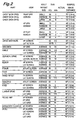
- X-ray imaging settings are selected by a radiologist or a x-ray technician and are based on exposure guide tables. Prior to imaging a patient, the radiologist or x-ray technician chooses the anatomic view to be imaged and estimates the size of the patient. The exposure guide tables are then examined and used to provide a value for the beam quality, kV p , and the amount of x-rays, mAs, for the desired anatomical view and approximate patient size. An example of an exposure guide table is shown in Fig. 2.
- the exposure guide table suggests that 75 kV p and 3 mAs be used as values for the beam quality and the amount of x-rays, respectively.
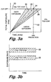
- Fig. 3a is graph showing the relationship between total exposure and time with the suggested kV p - and mAs values used as cutoffs.
- the graph shows how film exposure increases linearly during an ideal x-ray procedure as shown by an optimum trajectory line 28. As the time increases so does the exposure of x-rays. Eventually, the x-ray tube 12 is shut off when the exposure reaches the suggested k Vp value as shown by line 30.
- the graph shows a mAs value suggested from an exposure guide table which is used for exposure duration as shown by line 32. In the ideal case, all three of these lines intersect at a single point 34, indicating that the exposure is on track.
- Fig. 3b is a graph showing the relationship between exposure rate., which is the derivative of total exposure and time. If there is an error in selecting the anatomic view or estimating the patient size or a misalignment of the sensor, then these lines will no longer intersect at a single point. Any one of these errors will cause the film to be either overexposed or underexposed and may cause overexposure to the patient. In order to account for these errors, the erroneous exposure needs to be detected and corrected to provide the proper amount of tube voltage.
- the present invention is able to detect either an overexposed or an underexposed condition by tracking the total exposure rate of the patient and comparing it to a predicted exposure rate.
- Fig. 4 describes the series of steps performed by the exposure control unit 22 for detecting erroneous exposures.
- the operation is initiated at 40 where the radiologist or x-ray technician selects the anatomic view to be imaged and estimates the size of the patient.
- An illustrative list of possible anatomic views for different parts of the body is shown in Fig. 2.
- an exposure guide table such as the one in Fig. 2 is used at 42 to suggest a value for the beam quality, kV, and the amount of x-rays, mAs.
- the exposure guide table would suggest that 55 kV p and 2.5 mAs be used as values for the beam quality and the amount of x-rays, respectively.
- the film threshold i.e., brightness
- the exposure time is determined from the suggested mAs value and the current being provided by the x-ray generator controller 24.
- the predicted exposure rate is determined at 46 by dividing the brightness by the exposure time.
- the patient is then exposed to an x-ray beam at 48 having the suggested x-ray beam quality (kV) and x-ray quantity (mAs) values.
- the actual exposure rate to the patient is then measured at 50.
- the actual exposure rate is then integrated at 52 to determine the total exposure, which is compared to the predicted exposure rate at 54.
- the compared value is then used to determine if the exposure of the patient is within a predetermined tolerance. If the compared value is not within the predetermined tolerance at 56, then the exposure is stopped at 58 and the operator is signaled to recheck the x-ray settings. However, if the compared value is within the predetermined tolerance at 56, then the exposure is continued at 60 and the total exposure is compared to a predetermined threshold value at 62. If the total exposure is less than the predetermined threshold, then the exposure continues until the total exposure is equal to the predetermined threshold. Once the total exposure is equal to the predetermined threshold then the exposure is stopped at 58 and an image on the film is recorded.
- the present invention is able to correct these exposures by quickly suggesting a new voltage value (kV) and adjusting the x-ray generator 24 by the suggested amount.
- Fig. 5 sets forth the operation performed by the exposure control unit 22 to correct erroneous exposures.
- the radiologist or x-ray technician selects the anatomic view to be imaged and estimates the size of the patient at 64. After the anatomic view and patient size has been selected an exposure guide table such as the one in Fig. 2 is used at 66 to suggest a value for the beam quality (kV) and the amount of x-rays (mAs).
- the film threshold i.e., brightness
- the predicted exposure rate is determined at 70 by dividing the brightness by the exposure time.
- the patient is then exposed to an x-ray beam at 72 having the suggested x-ray beam quality (kV) and x-ray quantity (mAs) values.
- the actual exposure rate to the patient is then measured at 74.
- the actual exposure rate is then integrated at 76 to determine the total exposure which is compared to the predicted exposure rate at 78.
- the compared value is then used to determine if the exposure of the patient is within a predetermined tolerance. If the compared value is not within the predetermined tolerance at 80, then the exposure is continued at 82. However, if the compared value is within the predetermined tolerance at 80, then the actual patient size is computed at 84.
- the patient size is computed by using the brightness function for the imaging system which is defined as the function of kV, mAs, and the patient size. Thus, if the brightness, kV, and mAs values are known, then the patient size can be computed. Since the brightness rate (i.e., exposure rate), kV, and mAs values are known, then the patient size can be computed Then the computed actual patient-size is used to determine a new x-ray beam quality value (kV) at 86. The new x-ray beam quality value (kV) is determined by using a look-up table containing suggested values for adjusting kV given the initial kV, mAs, and patient size values.
- the brightness function for the imaging system which is defined as the function of kV, mAs, and the patient size.
- the look-up table will generate a suggested new kV value.
- the exposure of the patient is adjusted according to the new x-ray beam quality value (kV) and the exposure is continued at 88.
- the total exposure to the patient is then determined at 90.
- the total exposure is then compared to a predetermined threshold value at 92. If the total exposure is less than the predetermined threshold, then the exposure is continued at 88. Steps 88-92 continue until the total exposure equals the predetermined threshold. Once the total exposure equals the predetermined threshold then the exposure is continued at 82 and the image on the film is later recorded.
- a second embodiment of correcting erroneous exposures is set forth in the flow chart of Fig. 6.
- the operation is initiated at 94 where the radiologist or x-ray technician selects the anatomic view to be imaged and estimates the size of the patient.
- An illustrative list of possible anatomic views for different parts of the body is shown in Fig. 2.
- an exposure guide table such as the one in Fig. 2 is used at 96 to suggest a value for the beam quality (kV) and the amount of x-rays (mAs).
- the film threshold i.e., brightness
- exposure time is determined.
- the predicted exposure rate is determined at 100 by dividing the brightness by the exposure time.
- the patient is then exposed at 102 to an x-ray beam having the suggested x-ray beam quality (kV) and x-ray quantity (mAs) values.
- the actual exposure rate exposed to the patient is then measured at 104.
- the actual exposure rate is then integrated at 106 to determine total exposure which is compared to the predicted exposure rate at 108.
- the compared value is then used to determine if the patient is being exposed at a correct level. If the compared value is satisfactory at 110, then the exposure is completed at 112. However, if the compared value is not satisfactory at 110, then the exposure is adjusted at 114 and a new x-ray beam quality value (kV) is suggested at 116.
- the new x-ray beam quality value (kV) is suggested by using a look-up table as previously described to suggest a new x-ray quality value from the anatomical view and the predicted and actual exposure rates. More specifically, the selected anatomical view is used to index a row of the table. Each row represents a pairwise association from exposure rate to x-ray quality (kV). The actual exposure rate is located in the table, giving a suggested x-ray quality value, then interpolation may be used if a more precise solution is needed. In addition to using a look-up table it is within the scope of the present invention to use other mechanisms such as fuzzy logic and empirical curve fitting. After locating a new x-ray quality value, the exposure is continued at 118.
- the total exposure to the patient is then determined at 120.
- the total exposure is then compared to a predetermined threshold value at 122. If the total exposure is less than the predetermined threshold, then the exposure is continued at 118. Steps 118-122 continue until the total exposure equals the predetermined threshold. Once the total exposure equals the predetermined threshold then the exposure is completed at 112 and the image on the film is later recorded.
- the present invention has disclosed a procedure for detecting erroneous exposures that arise because of operator errors such as misalignment or setting errors. By detecting some of the incorrect exposures before completion, and aborting them before completed, patients will receive fewer x-rays, operating costs will decrease, while patient care will improve due to faster diagnosis, less repositioning, and increased availability.
- the present invention has disclosed a mechanism for improving image quality by correcting erroneous exposures. In particular, the present invention improves image quality by controlling the exposure rate as well as the total exposure through modifications to the x-ray beam quality and x-ray beam quantity values.
Landscapes
- Health & Medical Sciences (AREA)
- General Health & Medical Sciences (AREA)
- Toxicology (AREA)
- Apparatus For Radiation Diagnosis (AREA)
- X-Ray Techniques (AREA)
Claims (8)
- Verfahren zum Erfassen einer fehlerhaften Bestrahlung, die während einer Röntgen-Bildgebung eines Patienten (14) erzeugt wird, enthaltend die Schritte:Wählen (64, 94) von Röntgenbildeinstellungen zum Abbilden des Patienten,Generieren (66, 96) von Röntgenstrahl-Qualitäts- und Röntgenstrahl-Quantitätswerten aus den gewählten Röntgenbildeinstellungen,Voraussagen (70, 100) einer Bestrahlungsrate aus den Röntgenstrahl-Qualitäts- und Röntgenstrahl-Quantitätswerten, wobei die vorausgesagte Bestrahlungsrate auf der Röntgenfilm-Helligkeit und der Bestrahlungszeit basiert,Bestrahlen (72, 102) des Patienten mit einem Röntgenstrahl, der die generierten Röntgenstrahl-Qualitäts- und Röntgenstrahl-Quantitätswerte hat,Ermitteln (76, 106) der Gesamtbestrahlung des Patienten,Vergleichen(78, 108) der Gesamtbestrahlung mit der vorausgesagten Bestrahlungsrate, woraus ein verglichener Wert resultiert, undVerwenden (80, 110) des verglichenen Wertes um zu ermitteln, ob der Patient bei einem fehlerhaften Wert bestrahlt worden ist, gekennzeichnet durch
Beenden (82, 112) der Bestrahlung, wenn der Patient bei einem unrichtigen Wert bestrahlt worden ist, und
Vorschlagen (86, 116) eines neuen Röntgenstrahl-Qualitätswertes, wenn der Patient einem unrichtigen Wert ausgesetzt wird, wobei der vorgeschlagene Röntgenstrahl-Qualitätswert auf der tatsächlichen Grösse (84, 114) des Patienten basiert, die aus der Gesamtbestrahlung ermittelt ist. - Verfahren nach Anspruch 1, wobei die gewählten Röntgenbildeinstellungen ein anatomisches Bild und eine Näherung der Grösse des Patienten aufweisen.
- Verfahren nach Anspruch 1 oder 2, wobei ferner der Schritt vorgesehen ist, daß die Bestrahlung des Patienten gemäß dem neuen Röntgenqualitätswert eingestellt wird (88, 118).
- Verfahren nach Anspruch 1, 2 oder 3, wobei der Schritt des Vorschlagens eines neuen Röntgenqualitätswertes enthält, daß eine Tabelle (Fig. 2) verwendet wird, die neue Röntgenqualitätswerte enthält, die den vorausgesagten und gesamten Bestrahlungsraten entsprechen.
- Vorrichtung (10) zum Erfassen einer fehlerhaften Bestrahlung, die während einer Röntgen-Bildgebung eines Patienten (14) erzeugt ist, wobei die Vorrichtung enthält:Mittel (22) zum Wählen von Röntgenbildeinstellungen zum Abbilden des Patienten (14) undMittel (22) zum Generieren von Röntgenstrahl-Qualitätsund Röntgenstrahl-Quantitätswerten aus den gewählten Röntgenbildeinstellungen,Mittel (22) zum Voraussagen einer Bestrahlungsrate aus den Röntgenstrahl-Qualitäts- und Röntgenstrahl-Quantitätswerten, wobei die vorausgesagte Bestrahlungsrate auf der Röntgenfilm-Helligkeit und der Bestrahlungszeit basiert,eine Röntgenröhre (12) zum Bestrahlen des Patienten (14) mit einem Röntgenstrahl, der die generierten Röntgenstrahl-Qualitäts- und Röntgenstrahl-Quantitätswerte hat,einen Sensor (18) zum Messen einer tatsächlichen Bestrahlungsrate des Patienten (14);Mittel (22) zum Ermitteln der Gesamtbestrahlung aus der tatsächlichen Bestrahlungsrate,Mittel (22) zum Vergleichen der Gesamtbestrahlung mit der vorausgesagten Bestrahlungsrate, woraus ein verglichener Wert resultiert,Mittel (22) zum Verwenden des verglichenen Wertes um zu ermitteln, ob der Patient bei einem fehlerhaften Wert bestrahlt worden ist, gekennzeichnet durchMittel (22) zum Beenden der Bestrahlung, wenn der Patient bei einem unrichtigen Wert bestrahlt worden ist, undMittel (22) zum Vorschlagen eines neuen Röntgenstrahl-Qualitätswertes, wenn der Patient einem unrichtigen Wert ausgesetzt ist, wobei der vorgeschlagene neue Röntgenstrahl-Qualitätswert auf der tatsächlichen Grösse des Patienten basiert, die aus der Gesamtbestrahlung ermittelt ist.
- Vorrichtung nach Anspruch 5, wobei die gewählten Röntgenbildeinstellungen ein anatomisches Bild und eine Näherung der Grösse des Patienten aufweisen.
- Vorrichtung nach.Anspruch 5 oder 6, wobei ferner Mittel (22) vorgesehen sind zum Einstellen (88, 118) der Bestrahlung des Patienten gemäß dem neuen Röntgenqualitätswert.
- Vorrichtung nach Anspruch 5, 6 oder 7, wobei die Vorschlagsmittel eine Tabelle (Fig. 2) aufweisen, die neue Röntgenqualitätswerte enthält, die den vorausgesagten und gesamten Bestrahlungsraten entsprechen.
Applications Claiming Priority (2)
| Application Number | Priority Date | Filing Date | Title |
|---|---|---|---|
| US08/650,677 US5694449A (en) | 1996-05-20 | 1996-05-20 | Method and system for detecting and correcting erroneous exposures generated during x-ray imaging |
| US650677 | 1996-05-20 |
Publications (2)
| Publication Number | Publication Date |
|---|---|
| EP0809422A1 EP0809422A1 (de) | 1997-11-26 |
| EP0809422B1 true EP0809422B1 (de) | 2004-01-02 |
Family
ID=24609844
Family Applications (1)
| Application Number | Title | Priority Date | Filing Date |
|---|---|---|---|
| EP97303383A Expired - Lifetime EP0809422B1 (de) | 1996-05-20 | 1997-05-19 | Verfahren und Vorrichtung zur Erkennung und Korrektur von fehlerhaften Belichtungen während der Bilderzeugung mittels Röntgenstrahlen |
Country Status (4)
| Country | Link |
|---|---|
| US (1) | US5694449A (de) |
| EP (1) | EP0809422B1 (de) |
| JP (1) | JPH1043170A (de) |
| DE (1) | DE69727007T2 (de) |
Cited By (1)
| Publication number | Priority date | Publication date | Assignee | Title |
|---|---|---|---|---|
| EP4454568A1 (de) * | 2023-04-28 | 2024-10-30 | Canon Kabushiki Kaisha | Strahlungsbildgebungsvorrichtung und strahlungsbildgebungssystem |
Families Citing this family (21)
| Publication number | Priority date | Publication date | Assignee | Title |
|---|---|---|---|---|
| WO1998048600A2 (en) * | 1997-04-24 | 1998-10-29 | Koninklijke Philips Electronics N.V. | X-ray examination apparatus including an exposure control system |
| US6422751B1 (en) * | 1998-08-07 | 2002-07-23 | General Electric Company | Method and system for prediction of exposure and dose area product for radiographic x-ray imaging |
| DE19919423B4 (de) | 1999-04-28 | 2005-07-28 | Siemens Ag | Computertomographie(CT)-Gerät |
| US6222907B1 (en) * | 1999-07-12 | 2001-04-24 | General Electric Company | Image quality optimization using an X-ray model based optimization |
| US6233310B1 (en) * | 1999-07-12 | 2001-05-15 | General Electric Company | Exposure management and control system and method |
| US6330299B1 (en) | 2000-06-10 | 2001-12-11 | Ge Medical Systems Global Technology Company, Llc | System and method for determining dose area product in an X-ray imaging system |
| WO2003010555A2 (en) * | 2001-07-24 | 2003-02-06 | Case Western Reserve University | X-ray dose control based on patient size |
| US6687327B2 (en) * | 2001-11-15 | 2004-02-03 | Ge Medical Systems Global Technology Co., Llc | System and method of medical imaging having task and/or patient size dependent processing |
| WO2004071303A1 (en) * | 2003-02-11 | 2004-08-26 | Philips Intellectual Property & Standards Gmbh | X-ray device having a collimator, and method of setting the latter |
| US20040179651A1 (en) * | 2003-03-12 | 2004-09-16 | Canon Kabushiki Kaisha | Automated quality control for digital radiography |
| EP1627558A1 (de) * | 2003-05-16 | 2006-02-22 | Philips Intellectual Property & Standards GmbH | Verfahren und vorrichtung zur belichtung von röntgenbildern |
| US20050053199A1 (en) * | 2003-09-04 | 2005-03-10 | Miles Dale A. | Portable x-ray device and method |
| JP4119835B2 (ja) * | 2003-12-26 | 2008-07-16 | ジーイー・メディカル・システムズ・グローバル・テクノロジー・カンパニー・エルエルシー | 被曝線量計算方法およびx線撮影装置 |
| US7006600B1 (en) * | 2004-01-15 | 2006-02-28 | Progeny, Inc. | Integrated digital dental x-ray system |
| CN102413764B (zh) * | 2009-04-24 | 2014-05-07 | 株式会社日立医疗器械 | X射线诊断装置及x射线光阑控制方法 |
| CN101926650B (zh) * | 2009-06-26 | 2014-04-30 | Ge医疗系统环球技术有限公司 | 实际皮肤入射剂量率计算装置及方法和x光机 |
| JP5611213B2 (ja) * | 2009-08-28 | 2014-10-22 | 株式会社日立メディコ | 移動型x線装置 |
| JP5689734B2 (ja) * | 2011-04-20 | 2015-03-25 | 株式会社東芝 | X線ct装置 |
| JP6309250B2 (ja) | 2012-11-14 | 2018-04-11 | キヤノンメディカルシステムズ株式会社 | X線ct装置、x線ct装置の制御プログラム |
| DE102016123846A1 (de) * | 2016-12-08 | 2018-06-14 | Visus Health It Gmbh | Detektorband für Röntgenfilm |
| EP3420909A1 (de) * | 2017-06-27 | 2019-01-02 | Koninklijke Philips N.V. | Schutz vor missbrauch von röntgenstrahlen |
Family Cites Families (8)
| Publication number | Priority date | Publication date | Assignee | Title |
|---|---|---|---|---|
| US4119856A (en) * | 1973-09-07 | 1978-10-10 | Siemens Aktiengesellschaft | X-ray diagnostic apparatus for producing series exposures |
| DE2546948C3 (de) * | 1975-10-20 | 1980-05-29 | Siemens Ag, 1000 Berlin Und 8000 Muenchen | Röntgendiagnostikanlage für Röntgenaufnahmen mit Mitteln zur organprogrammierten Einstellung der Aufnahmewerte sowie mit einem Röntgenbelichtungsautomaten |
| US4845771A (en) * | 1987-06-29 | 1989-07-04 | Picker International, Inc. | Exposure monitoring in radiation imaging |
| US5301220A (en) * | 1992-09-03 | 1994-04-05 | Picker International, Inc. | Multi-mode acquisition x-ray imaging method and apparatus |
| US5319696A (en) * | 1992-10-05 | 1994-06-07 | General Electric Company | X-ray dose reduction in pulsed systems by adaptive X-ray pulse adjustment |
| FI941589L (fi) * | 1994-04-07 | 1996-01-12 | Stig Svensson | Laite röntgenkuvien ottamiseksi |
| FI98037C (fi) * | 1994-07-18 | 1997-03-25 | Instrumentarium Oy | Menetelmä röntgenkuvauslaitteen valotusarvojen mittaamiseksi kuvausarvojen automaattista säätöä varten |
| EP0746966B1 (de) * | 1994-12-23 | 2003-07-30 | Koninklijke Philips Electronics N.V. | Röntgenuntersuchungsapparat mit einer belichtungssteuerschaltung |
-
1996
- 1996-05-20 US US08/650,677 patent/US5694449A/en not_active Expired - Fee Related
-
1997
- 1997-05-16 JP JP9126900A patent/JPH1043170A/ja not_active Withdrawn
- 1997-05-19 DE DE69727007T patent/DE69727007T2/de not_active Expired - Fee Related
- 1997-05-19 EP EP97303383A patent/EP0809422B1/de not_active Expired - Lifetime
Cited By (1)
| Publication number | Priority date | Publication date | Assignee | Title |
|---|---|---|---|---|
| EP4454568A1 (de) * | 2023-04-28 | 2024-10-30 | Canon Kabushiki Kaisha | Strahlungsbildgebungsvorrichtung und strahlungsbildgebungssystem |
Also Published As
| Publication number | Publication date |
|---|---|
| DE69727007D1 (de) | 2004-02-05 |
| EP0809422A1 (de) | 1997-11-26 |
| US5694449A (en) | 1997-12-02 |
| JPH1043170A (ja) | 1998-02-17 |
| DE69727007T2 (de) | 2004-10-28 |
Similar Documents
| Publication | Publication Date | Title |
|---|---|---|
| EP0809422B1 (de) | Verfahren und Vorrichtung zur Erkennung und Korrektur von fehlerhaften Belichtungen während der Bilderzeugung mittels Röntgenstrahlen | |
| US7545915B2 (en) | Dose rate control in an X-ray system | |
| EP0942682B1 (de) | Einstellbare rechnergestützte tomographie anlage | |
| US6744846B2 (en) | Method and apparatus for automatic exposure control in CT scanning | |
| US7116756B2 (en) | X-ray diagnostic apparatus with a body mass index calculator for controlling x-ray emissions | |
| US6459765B1 (en) | Automatic exposure control and optimization in digital x-ray radiography | |
| US4763343A (en) | Method and structure for optimizing radiographic quality by controlling X-ray tube voltage, current, focal spot size and exposure time | |
| USRE33634E (en) | Method and structure for optimizing radiographic quality by controlling X-ray tube voltage, current focal spot size and exposure time | |
| US20100002831A1 (en) | Portable x-ray detector with grid sensing unit and x-ray imaging system for automatic exposure setting for the portable x-ray detector | |
| TW201817286A (zh) | 用於數位x光機的自動曝露控制系統與其方法 | |
| EP0291502B1 (de) | Verfahren und vorrichtung zur steuerung der röntgenstrahlung einer röntgenstrahlvorrichtung, insbesondere eines mammographen | |
| US20240161274A1 (en) | System and Method for Exposure Control and Imaging Technique Optimization Employing a Preshot X-Ray Image | |
| US4486896A (en) | X-Ray generator incorporating automatic correction of a dose-determining exposure parameter | |
| US7110494B2 (en) | X-ray diagnostic apparatus with a patient weighting device associated with the patient positioning table | |
| Young et al. | Dose and image quality in mammography with an automatic beam quality system | |
| JPH04229994A (ja) | X線フィルム露出時間の自動決定方法及びその実施装置 | |
| US4035649A (en) | X-ray generator for a tomography apparatus | |
| US5008914A (en) | Quantitative imaging employing scanning equalization radiography | |
| EP4684732A1 (de) | Verfahren und verarbeitungsvorrichtung zur bestimmung von medizinischen bilderfassungsparametern unter verwendung anatomischer informationen | |
| EP0777406A1 (de) | Vorrichtung zur automatischen Belichtungsmessung in einem Rötngenapparat für die Mammographie | |
| Eraso et al. | Clinical and in vitro film quality comparison of manual and automatic exposure control in panoramic radiography | |
| JPH04366598A (ja) | 自動露出機構付きx線撮影装置 | |
| Geise et al. | Routine quality control tests for film–screen mammographic systems with automatic exposure control | |
| Jenkins | Automatic Exposure Control | |
| Jacob et al. | Does Availability of Image Post-Processing Facility on Digital Radiography Systems Influence Radiographers’ Attitude Towards Proper Radiographic Technique? A Single Center Study |
Legal Events
| Date | Code | Title | Description |
|---|---|---|---|
| PUAI | Public reference made under article 153(3) epc to a published international application that has entered the european phase |
Free format text: ORIGINAL CODE: 0009012 |
|
| AK | Designated contracting states |
Kind code of ref document: A1 Designated state(s): DE NL |
|
| 17P | Request for examination filed |
Effective date: 19980526 |
|
| 17Q | First examination report despatched |
Effective date: 20020125 |
|
| GRAH | Despatch of communication of intention to grant a patent |
Free format text: ORIGINAL CODE: EPIDOS IGRA |
|
| GRAS | Grant fee paid |
Free format text: ORIGINAL CODE: EPIDOSNIGR3 |
|
| GRAA | (expected) grant |
Free format text: ORIGINAL CODE: 0009210 |
|
| AK | Designated contracting states |
Kind code of ref document: B1 Designated state(s): DE NL |
|
| REF | Corresponds to: |
Ref document number: 69727007 Country of ref document: DE Date of ref document: 20040205 Kind code of ref document: P |
|
| PGFP | Annual fee paid to national office [announced via postgrant information from national office to epo] |
Ref country code: NL Payment date: 20040429 Year of fee payment: 8 |
|
| PGFP | Annual fee paid to national office [announced via postgrant information from national office to epo] |
Ref country code: DE Payment date: 20040630 Year of fee payment: 8 |
|
| PLBE | No opposition filed within time limit |
Free format text: ORIGINAL CODE: 0009261 |
|
| STAA | Information on the status of an ep patent application or granted ep patent |
Free format text: STATUS: NO OPPOSITION FILED WITHIN TIME LIMIT |
|
| 26N | No opposition filed |
Effective date: 20041005 |
|
| PG25 | Lapsed in a contracting state [announced via postgrant information from national office to epo] |
Ref country code: NL Free format text: LAPSE BECAUSE OF NON-PAYMENT OF DUE FEES Effective date: 20051201 Ref country code: DE Free format text: LAPSE BECAUSE OF NON-PAYMENT OF DUE FEES Effective date: 20051201 |
|
| NLV4 | Nl: lapsed or anulled due to non-payment of the annual fee |
Effective date: 20051201 |