EP0809277B1 - Verfahren zur Abdichtung einer Halogenlampe - Google Patents
Verfahren zur Abdichtung einer Halogenlampe Download PDFInfo
- Publication number
- EP0809277B1 EP0809277B1 EP97303245A EP97303245A EP0809277B1 EP 0809277 B1 EP0809277 B1 EP 0809277B1 EP 97303245 A EP97303245 A EP 97303245A EP 97303245 A EP97303245 A EP 97303245A EP 0809277 B1 EP0809277 B1 EP 0809277B1
- Authority
- EP
- European Patent Office
- Prior art keywords
- envelop
- lamp
- end portion
- lamp envelop
- mount
- Prior art date
- Legal status (The legal status is an assumption and is not a legal conclusion. Google has not performed a legal analysis and makes no representation as to the accuracy of the status listed.)
- Expired - Lifetime
Links
- 238000007789 sealing Methods 0.000 title claims description 84
- 238000000034 method Methods 0.000 title claims description 41
- 229910052736 halogen Inorganic materials 0.000 title claims description 33
- 150000002367 halogens Chemical class 0.000 title claims description 33
- 239000000725 suspension Substances 0.000 claims description 41
- 238000010438 heat treatment Methods 0.000 claims description 18
- 239000011888 foil Substances 0.000 description 48
- 239000007789 gas Substances 0.000 description 33
- IJGRMHOSHXDMSA-UHFFFAOYSA-N Atomic nitrogen Chemical compound N#N IJGRMHOSHXDMSA-UHFFFAOYSA-N 0.000 description 10
- 230000003247 decreasing effect Effects 0.000 description 8
- 238000010276 construction Methods 0.000 description 7
- 239000011261 inert gas Substances 0.000 description 7
- 238000004880 explosion Methods 0.000 description 6
- 238000003780 insertion Methods 0.000 description 6
- 230000037431 insertion Effects 0.000 description 6
- 229910052757 nitrogen Inorganic materials 0.000 description 5
- 239000007788 liquid Substances 0.000 description 4
- VYPSYNLAJGMNEJ-UHFFFAOYSA-N Silicium dioxide Chemical compound O=[Si]=O VYPSYNLAJGMNEJ-UHFFFAOYSA-N 0.000 description 3
- 239000011521 glass Substances 0.000 description 3
- 238000004519 manufacturing process Methods 0.000 description 3
- 238000007254 oxidation reaction Methods 0.000 description 3
- XKRFYHLGVUSROY-UHFFFAOYSA-N Argon Chemical compound [Ar] XKRFYHLGVUSROY-UHFFFAOYSA-N 0.000 description 2
- 238000001816 cooling Methods 0.000 description 2
- 239000012634 fragment Substances 0.000 description 2
- 239000000463 material Substances 0.000 description 2
- 229910052751 metal Inorganic materials 0.000 description 2
- 239000002184 metal Substances 0.000 description 2
- 230000001590 oxidative effect Effects 0.000 description 2
- 230000002093 peripheral effect Effects 0.000 description 2
- 229920002379 silicone rubber Polymers 0.000 description 2
- 239000004945 silicone rubber Substances 0.000 description 2
- 229910001220 stainless steel Inorganic materials 0.000 description 2
- 239000010935 stainless steel Substances 0.000 description 2
- WFKWXMTUELFFGS-UHFFFAOYSA-N tungsten Chemical compound [W] WFKWXMTUELFFGS-UHFFFAOYSA-N 0.000 description 2
- 229910052721 tungsten Inorganic materials 0.000 description 2
- 239000010937 tungsten Substances 0.000 description 2
- PRPINYUDVPFIRX-UHFFFAOYSA-N 1-naphthaleneacetic acid Chemical compound C1=CC=C2C(CC(=O)O)=CC=CC2=C1 PRPINYUDVPFIRX-UHFFFAOYSA-N 0.000 description 1
- ZOKXTWBITQBERF-UHFFFAOYSA-N Molybdenum Chemical compound [Mo] ZOKXTWBITQBERF-UHFFFAOYSA-N 0.000 description 1
- 235000002597 Solanum melongena Nutrition 0.000 description 1
- 244000061458 Solanum melongena Species 0.000 description 1
- 229910052786 argon Inorganic materials 0.000 description 1
- 238000001704 evaporation Methods 0.000 description 1
- 230000008020 evaporation Effects 0.000 description 1
- 239000005337 ground glass Substances 0.000 description 1
- 239000012212 insulator Substances 0.000 description 1
- 238000009940 knitting Methods 0.000 description 1
- 229910052750 molybdenum Inorganic materials 0.000 description 1
- 239000011733 molybdenum Substances 0.000 description 1
- 239000011347 resin Substances 0.000 description 1
- 229920005989 resin Polymers 0.000 description 1
- 230000000979 retarding effect Effects 0.000 description 1
- 238000007493 shaping process Methods 0.000 description 1
- 238000004804 winding Methods 0.000 description 1
Images


Classifications
-
- H—ELECTRICITY
- H01—ELECTRIC ELEMENTS
- H01K—ELECTRIC INCANDESCENT LAMPS
- H01K1/00—Details
- H01K1/28—Envelopes; Vessels
- H01K1/34—Double wall vessels
-
- H—ELECTRICITY
- H01—ELECTRIC ELEMENTS
- H01K—ELECTRIC INCANDESCENT LAMPS
- H01K3/00—Apparatus or processes adapted to the manufacture, installing, removal, or maintenance of incandescent lamps or parts thereof
- H01K3/20—Sealing-in wires directly into the envelope
-
- H—ELECTRICITY
- H01—ELECTRIC ELEMENTS
- H01K—ELECTRIC INCANDESCENT LAMPS
- H01K3/00—Apparatus or processes adapted to the manufacture, installing, removal, or maintenance of incandescent lamps or parts thereof
- H01K3/26—Closing of vessels
-
- Y—GENERAL TAGGING OF NEW TECHNOLOGICAL DEVELOPMENTS; GENERAL TAGGING OF CROSS-SECTIONAL TECHNOLOGIES SPANNING OVER SEVERAL SECTIONS OF THE IPC; TECHNICAL SUBJECTS COVERED BY FORMER USPC CROSS-REFERENCE ART COLLECTIONS [XRACs] AND DIGESTS
- Y02—TECHNOLOGIES OR APPLICATIONS FOR MITIGATION OR ADAPTATION AGAINST CLIMATE CHANGE
- Y02B—CLIMATE CHANGE MITIGATION TECHNOLOGIES RELATED TO BUILDINGS, e.g. HOUSING, HOUSE APPLIANCES OR RELATED END-USER APPLICATIONS
- Y02B20/00—Energy efficient lighting technologies, e.g. halogen lamps or gas discharge lamps
Definitions
- the present invention relates to a method of sealing halogen lamp without using a tip tube.
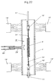
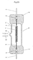
- Fig. 23 shows a conventional halogen lamp (B') having a typical configuration wherein sealing foils (10') are respectively embedded in seal portions (13') of a lamp envelop (1'), and the inner end of each sealing foil (10') is welded to a lead portion of a filament, while the outer end thereof is welded to a corresponding outer lead pin (11') extending to project outwardly from the seal portion (13').
- the gas within the lamp envelop (1') is sucked out through the tip tube (29') connected to the lamp envelop (1') to provide a high vacuum in the lamp envelop (1').
- a required gas is filled into the lamp envelop (1'), and finally the tip tube (29') is cut-sealed at the base portion thereof by heating.
- the inert gas is supplied into the lamp envelop (1') to retain the sealing foils (10') as well as the lamp envelop (1') in the non-oxidizing atmosphere so that the pinch-sealing can be achieved without oxidization of the surfaces of the sealing foils (10').
- air sometimes enters the lamp envelop (1') instantaneously from the open ends thereof depending on the position of a burner or the intensity of flame, thereby causing the surface of the sealing foils (10') to be slightly oxidized. This results in poor adhesion between the lamp envelop (1') and the sealing foil (10') in the seal portions (13'). which leads to a high possibility of leak accidents of the product.
- the surfaces of the sealing foil (10') are intensely oxidized and may be broken into fragments during the pinch-sealing. Further, where the outer lead pin (11') has a relatively small diameter, it may be burned out.
- the sealing foils (10') may be broken when applied with an increased pinching force greater than the breaking force in an attempt to enhance the adhesion between the seal portions (13') and the sealing foils (10'). Therefore, the relationship between the softening of the lamp envelop (1') and the pinching force is very delicate.
- the inert gas when the inert gas is supplied into the lamp envelop (1'), the gas flow causes the sealing foils (10') to flutter, hence, the position thereof to vary. Therefore, it is very difficult to pinch the lamp envelop (1') with the sealing foils (10') kept in predetermined positions within the seal portions (13'). Thus, a separate device is required for keeping the sealing foils (10') stationary.
- tip tube (29') results in a cut-sealed trace (30') of the tip tube (29') formed on a side surface of the lamp envelop. which not only renders the appearance of the lamp poor but also causes an internal strain to be left in peripheral portions thereof, decreasing the pressure resistance of the lamp envelop (1'). Repeating on/off operations of the lamp i.e., repeating heating and cooling of the lamp may eventually causes the lamp envelop to be broken from the cut-sealed trace (30').
- halogen lamps adaptable for commercial voltages of less power consumption in many countries have been demanded.
- the volume of a lamp envelop can not help being decreased.
- the lamp envelop can not be sufficiently cooled when it is immersed in liquid nitrogen for cutting the tip tube after a required gas is filled therein, because liquid nitrogen vaporizes due to the heat of a tip-off burner.
- the amount of the filling gas becomes insufficient and, hence, sufficient pressurizing of the lamp envelop can not be achieved.
- an object of the present invention to provide a novel method of sealing a halogen lamp, with which: the sealing foils are unlikely to be oxidized or broken; the outer lead pins are unlikely to burn out; a conventionally required tip tube can be dispensed with thereby providing a lamp envelop free of the cut-sealed trace; and the filling gas pressure can be increased.
- U.S. Patent No. 3,759,601 and European Patent Application No. 0,370,554 A 1 both disclose methods of sealing lamps comprising the steps of providing a lamp envelop having an envelop body, an open end portion and a closed end portion; inserting a mount including a filament into the lamp envelop through the open end portion thereof: heating the closed end portion of the lamp envelop to soften and shrink thereby sealingly embedding one end of the mount in the closed end portion of the lamp envelop, while providing a reduced pressure in the lamp envelop using a gas supply tube connected to the open end portion; filling the lamp envelop with a required gas using the gas supply tube; and heating the open end portion of the lamp envelop to soften and shrink thereby sealingly embedding the other end of the mount in the open end portion of the lamp envelop.
- a first aspect of the invention is characterised in that the open end portion of the lamp envelop comprises a narrow portion which is equal to or smaller in width than the envelop body, and a wide portion having an end opening which is connected to the gas supply tube, the wide portion being wider than the narrow portion, the narrow portion being heated to form a seal portion.
- the closed end portion of the lamp envelop is heated to shrink under a reduced pressure. Accordingly, where sealing foils are used in the mount, they can be assuredly embedded in the sealed portions thus shrunk without receiving any excessive force, hence, without any danger of breaking.
- the lamp envelop is completely closed on the closed end side, air does not enter from the outside into the lamp envelop through the closed end side and, hence, oxidization of the sealing foil or burning-out of an outer lead pin can be avoided on the closed end side.
- the sealing foils do not flatter by the flow of an inert gas, one end of the mount can be securely embedded in a central portion of the shrunk closed end portion of the lamp envelop.
- the closed end portion in the softened state may be pinched with an appropriate force for shaping.
- the sealing/embedding operation on the open end side may be carried out by pinching.
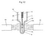
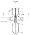
- the closed end portion may be formed to have the same width as that of the envelop body as shown in Fig. 11, or formed narrower than the envelop body as shown in Fig. 12, or may comprise a narrower portion to be heated and softened and the rest having the same width as that of the envelop body as shown in Fig. 13.
- the closed end portion be formed by inserting a sealing plug into an open end of the lamp envelop as shown in Fig. 4.
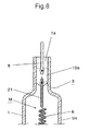
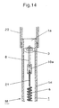
- the open end portion may be formed narrower than the envelop body as shown in Figs. 8 and 15, or formed to have the same width as that of the envelop body as shown in Fig. 14, or may comprise a narrower portion to be heated and softened and the rest having the same width as that of the envelop body as shown in Fig. 9.
- a method of sealing a halogen lamp comprising the steps of providing a lamp envelop having an envelop body, and first and second end portions which are open; inserting a mount including a filament into the lamp envelop and closing the first end portion, or closing the first end portion and inserting the mount into the lamp envelop; heating the first end portion thus closed of the lamp envelop to soften and shrink thereby sealingly embedding one end of the mount in the closed first end portion of the lamp envelop, while providing a reduced pressure in the lamp envelop using a gas supply tube connected to the open end portion; filling the lamp envelop with a required gas using the gas supply tube: and heating the second end portion of the lamp envelop to soften and shrink thereby sealingly embedding the other end of the mount in the open end portion of the lamp envelop.
- the second end portion of the lamp envelop comprises a narrow portion which is equal to or smaller in width than the envelop body, and a wide portion having an end opening which is connected to the gas supply tube, the wide portion being wider than the narrow portion, the narrow portion being heated to form a seal portion.
- the lamp envelop having open opposite end portions is used one of which ends is to be closed with a sealing plug formed of, for example, silicone rubber after or before the insertion of the mount into the lamp envelop.
- the sealing plug is not limited to such an insertion type formed of silicone rubber but may be of a cap type to be fitted over the end portion of the lamp envelop through an O-ring.
- the subsequent steps which are the same as those of the first method are carried out to make a halogen lamp.
- the lamp may be used without cutting unnecessary portions of the opposite end portions of the lamp envelop.
- sealing plug should be sufficiently spaced from the portion of the lamp envelop to be heated and softened, or should be cooled to avoid burning during the heating.
- the sealing plug will not actually be burnt because the filling gas thus heated convects in a reduced pressure. Also, where the lamp envelop is formed of quartz glass, the sealing plug will not be burnt due to the heat of the burner flame because quartz glass has a small thermal conductivity.
- the mount is inserted into the lamp envelop in such a manner that opposite ends of the mount are positioned in the open end portion and the closed end portion, respectively, of the lamp envelop.
- the opposite ends of the mount are respectively positioned in the open end portion and the closed end portion at least one of which is narrower than the envelop body, whereby the mount is easily aligned on the central axis of the lamp envelop by mere insertion.
- a resilient suspension member to the end of the mount to be positioned in the open end portion of the lamp envelop so as to position such end centrally of the corresponding end portion of the lamp envelop. The provision of the resilient suspension member allows the centering of the mount to be further facilitated.
- the mount preferably has a resilient suspension member at any portion thereof, the resilient suspension member resiliently engaging any portion of the lamp envelop when inserted into the lamp envelop.
- the resilient suspension member suspends the mount at a desired position within the lamp envelop to facilitate the axial positioning of the mount relative to the lamp envelop. Secondly, the resilient suspension member prevents the mount from axially shifting during the sealing of the closed end portion and the open end portion. Thirdly, where the end portion opposite the end portion engaged with the resilient suspension member is formed narrow, the resilient suspension member in cooperation with the narrow end portion (which may be open or closed) facilitates the centering of the mount relative to the lamp envelop.
- the resilient suspension member may be formed into various shapes as will be described later, and optimal one may be selected as required.
- the step of heating the closed end portion of the lamp envelop further includes pinch-sealing a heated and softened portion of the closed end portion.
- the step of heating the open end portion of the lamp envelop preferably further includes pinch-sealing a heated and soliened portion of the open end portion.
- the pinching operation in cooperation with the shrinking of each end portion enhances the adhesion between the sealing foils and the corresponding seal portions of the lamp envelop.
- the filling gas pressure within the lamp envelop can be increased, which leads to enhanced performance of the resulting lamp as well as to good appearance of the finished seal portions.
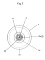
- a halogen lamp (Al) which is not fully in accordance with a first embodiment of the present invention is of a double-ended type having seal portions 13 comprising a shrunk portion le and a sealed portion 1g formed at opposite ends of a lamp envelop 1, and a filament 6 extending in a envelop body 1H.
- the filament 6 is of a double coil type of tungsten including at opposite ends thereof, lead portions 21 formed by covering a single coil by another coil, and the outer end of each lead portion 21 is welded to the inner end of each sealing foil 10.
- At least one support member (not shown) in the form of a vortex may be disposed to wind around an appropriate portion of the filament 6 so that a portion of the outer circumference of the vortex is fixedly embedded in a support fixing portion of the lamp envelop 1 formed by concavely denting the lamp envelop 1.
- each lead portion 21 is not limited to that described above. That is, the lead portion 21 may comprise a single coil portion of the filament 6 directly welded to the sealing foil 10, or connected to the sealing foil 10 through an inner lead pin (not shown).
- the sealing foils 10a and 10b are each typically formed of thin molybdenum foil having a thickness of from 20 to 30 um. At least a portion of each sealing foil is embedded in each seal portion 13, and the outer end of each sealing foil is welded to an outer lead pin 8 extending outwardly to project from the corresponding seal portion 13.
- the sealing foils 10a and 10b may be disposed to extend outwardly from the respective seal portions 13, and in that case, the outer lead pins 8 can be dispensed with.
- a first form of mount M in accordance with the present invention comprises filament 6, lead portions 21 connected to opposite ends of the filament 6 directly or through inner lead pins, sealing foils 10a and 10b respectively welded to the outer ends of the lead portions 21, and outer lead pins 8 respectively welded to the outer ends of the sealing foils 10a and 10b.
- a second form of mount M is of a sealing foil free type wherein opposite ends of filament 6 are respectively connected to outer lead pins 8 directly or through lead portions 21.
- a separate resilient suspension member 3 is usually attached to one of the outer lead pins 8.
- the sealing foil 10a has a width larger than the inside width of an open end portion 1a of the lamp envelop 1
- the sealing foil 10a serves as a resilient suspension member by resiliently engaging at the opposite edges thereof with the inner surface of the open end portion 1a of the lamp envelop 1 as shown in Figs. 7 and 8.
- the provision of the separate resilient suspension member 3 is not required, and hence it is possible to decrease the manufacturing cost and weight of a lamp.
- a portion of outer lead pin 8 is bent to serve as the resilient suspension member 3, which also leads to a decreased manufacturing cost and weight of a lamp.
- any other means for suspending mount M may be employed.
- Open end portion 1a comprises a narrow portion 1a1 having a smaller width than that of envelop body 1H and a wide portion 1a2 contiguous to the narrow portion 1a1 as shown in Fig 9. That is, only a portion 1f to be heated and softened may be formed narrower than envelop body 1H.
- a closed end portion 1b of lamp envelop 1 may be formed to have the same width as that of envelop body 1H as shown in Fig. 11, or formed narrower than the envelop body 1H as shown in Fig. 12, or comprise a portion 1d to be heated and softened which is formed narrower and the rest as shown in Fig. 13.
- Closed end portion 1b may be formed by fitting a sealing plug 1c into an open end as shown in Fig. 4.
- open end portion 1a and closed end portion 1b can be employed.
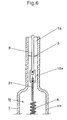
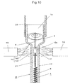
- resilient suspension member 3 is as follows. Separately provided resilient suspension member 3 may be formed by winding a thin metal wire into the form of vortex as shown in Fig. 1, or may comprise a resilient thin wire formed of, for example, stainless steel welded perpendicularly to outer lead pin 8 as shown in Figs. 6 and 9. In any case, when inserted into the lamp envelop 1, the resilient suspension member 3 resiliently engages the inner circumferential surface of the lamp envelop 1 to suspend the mount M centrally of the lamp envelop 1.
- Fig. 9 shows the case where open end portion 1a on the mount suspending side of lamp envelop 1 comprises a narrow portion 1a1 to be heated and softened which is narrower than envelop body 1H and a wide portion 1a2 contiguous to the narrow portion 1a1, and resilient suspension member 3 formed of a resilient thin wire of, for example, stainless steel resiliently engages the inner circumferential surface of the wide portion 1a2, thereby suspending the mount M centrally of the lamp envelop 1.
- sealing foil 10a also serves as resilient suspension member 3.
- the sealing foil 10a When inserted into open end portion 1a, the sealing foil 10a is wholly curved to resiliently engage the inner circumferential surface of the open end portion 1a, thereby suspending the mount M centrally of the lamp envelop 1.
- the leading end portion of the sealing foil 10a may be tapered for easier insertion into the open end portion 1a.
- Fig. 14 shows a case not fully in accordance with the invention where open end portion 1a is formed to have the same width as that of envelop body 1H, and resilient suspension member 3 is wound around corresponding outer lead pin 8 on the open end portion side so as to resiliently engage the inner circumferential surface of the lamp envelop 1.
- the resilient suspension member 3 is formed of a resilient thin wire having a vortex configuration.
- Fig. 15 Shown in Fig. 15 is a case not fully in accordance with the invention where a portion of outer lead pin 8 is bent into a spiral configuration to serve as resilient suspension member 3.
- the shape and position of resilient suspension member 3 is not limited to those described above. That is, resilient suspension member 3 may be of any form which can suspend mount M within the lamp envelop 1, and may be attached to any position as well as to the outer lead pin 8.
- Figs. 11 to 13 show the relationship between closed end portion 1b of the lamp envelop 1 and the corresponding end of mount M.
- the end of the mount M is suspendedly positioned in the closed end portion 1b having a relatively large width as shown in Fig. 11, or in the closed end portion 1b formed narrower than envelop body 1H as shown in Fig. 12.
- the end of the mount M is suspendedly positioned within closed end portion 1b so that corresponding sealing foil 10b is located in narrow portion 1d to be heated and softened as shown in Fig. 13.
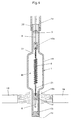
- lamp envelop 1 comprising envelop body 1H, open end portion 1a and opposite closed end portion 1b, each end portion having a width smaller than that of the envelop body 1H as shown in Fig. 1. Then, mount M of the first form is inserted into the lamp envelop 1 from the open end.
- resilient suspension member 3 resiliently engages the inner circumferential surface of the lamp envelop 1 to stop the mount M at an axially optimum position in the lamp envelop 1.
- lower outer lead pin 8 may abut against the bottom of the closed end portion 1b of the lamp envelop, or may be spaced therefrom.
- an inert gas may be filled into the lamp envelop to about 0.1 atm.
- a portion of the closed end portion 1b coinciding with lower sealing foil 10b is heated and softened. Since the inside of the lamp envelop 1 is kept in a substantial vacuum or in an inert gas atmosphere of about 0.1 atm, the sealing foil 10b is stably positioned centrally of the closed end portion 1b without being oxidized or fluttered, and further, the outer lead pin 8 is unlikely to be damaged by burning.
- thinner outer lead pins are required as filaments become smaller and thinner. Although such a thin outer lead pin is likely to be damaged by burning, the method of the present invention prevents the thin outer lead pin from burning.
- the heated and softened portion 1d pressed by the atmospheric pressure shrinks to embrace the entire sealing foil 10b.
- the softened portion may be subjected to a slight pinching to complete sealing, if necessary, and thus, the seal portion 13 is provided.
- a required gas is filled into the lamp envelop 1 from the open end portion 1a. Then, while cooling most portion of the lamp envelop 1 including the closed end portion 1b with liquid nitrogen if necessary, a portion of the open end portion 1a coinciding with the sealing foil 10a is heated and softened, and the heated portion 1f is sealed by natural shrinking or pinching to provide seal portion 13. After the opposite end portions are thus sealed, an unnecessary portion of at least the closed end portion 1b is cut away as required to provide a halogen lamp A1 shown in Fig. 3.
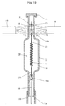
- Figs. 4 and 19 Shown in Figs. 4 and 19 are examples not fully in accordance with the invention each using lamp envelop 1 having opposite open end portions.
- mount M is inserted into the lamp envelop 1 so that resilient suspension member 3 is located within upper end portion, and then one end of the lamp envelop 1 is closed by fitting sealing plug 1c thereinto to provide closed end portion 1b.
- sealing plug 1C is fitted into one of the opposite open end portions to provide the closed end portion 1b before inserting the mount M into the lamp envelop 1.
- the subsequent steps are the same as those described above.
- Fig. 18 illustrates an example not fully in accordance with the invention where closed end portion 1b is oriented upward and resilient suspension member 3 is positioned therein.
- a halogen lamp A2 not fully in accordance with the invention formed using lamp envelop 1 of the type having opposite open end portions as described above.
- the halogen lamp A2 shown is in a state before cutting away unnecessary portions.
- the halogen lamp A2 may be used as it is or used after the unnecessary portions are cut away.
- Figs. 16 and 17 show a case not fully in accordance with the invention where sealing foils 10a and 10b are not used and opposite ends of filament 6 are each connected to outer lead pin 8 directly or through lead portion 21.
- This construction is suitable for a lamp envelop formed of hard glass.
- the shape and position of resilient suspension member 3 and the method of positioning the resilient suspension member 3 are the same as with the case where the mount M including the sealing foils 10a and 10b is used. Hence, the explanation thereof is omitted.
- each outer lead pin 8 may be extended through the seal portion 13 to project into the envelop body 1H, or each lead portion 21 may be extended through the seal portion 13 to protrude outwardly therefrom.
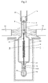
- halogen lamp Anot fully in accordance with the invention mounted vertically in an outer bulb 2 adaptable for typical incandescent lamps.
- a stem 4 is disposed within a lamp base insertion portion 7 of the outer bulb 2.
- a threaded lamp base 5 having the same size as that of a typical eggplant-shaped incandescent lamp.
- a central contact 17 disposed centrally of the threaded lamp base 5 through an insulator 16 is connected to one of stem-side lead pins 14 typically through an intermediate lead-in wire, and the other of the stem-side lead pins 14 is connected to the threaded lamp base 5 typically through an intermediate lead-in wire.
- outer bulb 2 may be a glass or a resin, and may be transparent or translucent like ground glass.
- the state of the outer surface of the bulb can be selected as desired. Further, the outer bulb may assume various forms as well as a typical eggplant-shaped outer bulb.
- the atmosphere within the outer bulb 2 is not limited to any particular one. That is, the inside of the outer bulb may be under inert atmosphere, or an increased or reduced pressure, or may be filled with air.
- an explosion resistant member 12 may be disposed to surround the halogen lamp A.
- the explosion resistant member 12 may be, for example, a cylindrical netting formed by knitting thin wires, or punched metal or a lath formed into a cylindrical configuration.
- the explosion resistant member 12 is directly or indirectly attached to one of the lead pins 14.
- the explosion resistant member 12 prevents fragments of the halogen lamp from scattering even when the halogen lamp serving as the inner bulb explodes by any reason, and hence, a secondary accident due to such explosion can be avoided.
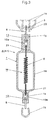
- Fig. 21 shows a case not fully in accordance with the invention where the double ended type halogen lamp A shown in Fig. 5 is housed in an elongate outer bulb 2.
- the closed end portion of the lamp envelop (which may be formed by closing an open end with the sealing plug) is heated to shrink with the inside of the lamp envelop in a substantial vacuum state or in a reduced pressure of an inert gas in accordance with the present invention. Accordingly, breakage and oxidization of the sealing foils can be avoided and, one end of the mount can be assuredly embedded centrally of the shrunk portion of the closed end side. Further, good adhesion can be provided between one end of the mount and the shrunk portion, which enables the inside of the lamp envelop to be pressurized, resulting in a halogen lamp having a higher brightness and a longer life.
- the mount can be easily positioned on the central axis of the lamp envelop just by inserting the mount into the lamp envelop.
- the construction free of a cutting trace of a tip tube allows the filling gas pressure in the envelop body to increase thereby retarding the evaporation of tungsten forming the filament. Accordingly, it is possible to remarkably enhance the performance of halogen lamps.
- the lamp envelop is free of the cutting trace of a tip tube, explosion of the lamp envelop, which would be conventionally caused by an internal strain due to such cutting trace, can be avoided. Accordingly, it is possible to considerably increase the filling gas pressure in the lamp envelop.
- the open end portions of lamp envelop has a portion wider than the rest, the existence of the wide portion can hinder burner flame from reaching the gas supply tube.
- the gas supply tube can be protected, and the distance between the lower end of the gas supply tube and the upper end of the envelop body can be shortened, which leads to a decreased cost of making a lamp.
- the mount can be suspended at any desired position within the lamp envelop. That is, the resilient suspension member not only facilitates the axial positioning of the mount relative to the lamp envelop but also enables the compulsory positioning of one end of the mount on the central axis of the open end portion of the lamp envelop. whereby the mount can be substantially centered relative to the lamp envelop.
- the pinching operation in cooperation with the shrinking of the softened portion enhances the adhesion between the sealing foil and the seal portion of the lamp envelop.
Landscapes
- Engineering & Computer Science (AREA)
- Manufacturing & Machinery (AREA)
- Vessels And Coating Films For Discharge Lamps (AREA)
- Resistance Heating (AREA)
Claims (10)
- Verfahren zum Abdichten einer Halogenlampe (A1), mit den Schritten:dadurch gekennzeichnet, dass der offene Endabschnitt (1a) der Lampenumhüllung (1) einen schmalen Abschnitt (1a1) umfasst, der in der Breite gleich oder kleiner ist als der Umhüllungskörper (1) und dass ein weiter Abschnitt (1a2) bereitgestellt ist , mit einer Endöffnung, die mit dem Gasversorgungsrohr (20) verbunden ist, wobei der weite Abschnitt (1a2) weiter ist als der schmale Abschnitt (1a1) und der schmale Abschnitt (1a1) erwärmt wird, um einen Dichtungsabschnitt auszubilden.Bereitstellen einer Lampenumhüllung (1) mit einem Umhüllungskörper (1H), einem offenen Endabschnitt (1a) und einem geschlossenen Endabschnitt (1b);Einsetzen einer einen Heizdraht (6) beinhaltenden Halterung (M) in die Lampenumhüllung (1) durch deren offenen Endabschnitt (1a);Erwärmen des geschlossenen Endabschnitts (1b) der Lampenumhüllung (1) zum Erweichen und Schrumpfen und dadurch abdichtendes Einbetten eines Endes der Halterung (M) in den geschlossenen Endabschnitt (1b) der Lampenumhüllung, während ein Unterdruck in der Lampenumhüllung (1) unter Verwendung eines mit dem offenen Endabschnitt (1a) verbundenen Gasversorgungsrohres (20) bereitgestellt wird;Füllen der Lampenumhüllung (1) mit einem erforderlichen Gas unter Verwendung des Gasversorgungsrohrs (20); undErwärmen des offenen Endabschnitts (1a) der Lampenumhüllung zum Erweichen und Schrumpfen und dadurch abdichtenden Einbetten des anderen Endabschnitts der Halterung (M) in dem offenen Endabschnitt (1a) der Lampenumhüllung (1),
- Verfahren zum Dichten einer Halogenlampe (A1), mit den Schritten:dadurch gekennzeichnet, dass der offene Endabschnitt (1a) der Lampenumhüllung (1) einen schmalen Abschnitt (1a1) umfasst, der in der Breite gleich oder kleiner ist als der Umhüllungskörper (1) und dass ein weiter Abschnitt (1a2) bereitgestellt ist , mit einer Endöffnung, die mit dem Gasversorgungsrohr (20) verbunden ist, wobei der weite Abschnitt (1a2) weiter ist als der schmale Abschnitt (1a1) und der schmale Abschnitt (1a1) erwärmt wird, um einen Dichtungsabschnitt auszubilden.Bereitstellen einer Lampenumhüllung (1) mit einem Umhüllungskörper (1H) und ersten und zweiten Endabschnitten (1b), (1a), die offen sind;Einsetzen einer einen Heizdraht beinhaltenden Halterung (M) in die Lampenumhüllung (1) und Schließen des ersten Endabschnittes (1b) oder Schließen des ersten Endabschnitts und Einsetzen der Halterung in die Lampenumhüllung (1);Erwärmen des solcherart von der Lampenumhüllung (1) geschlossenen ersten Endabschnitts (1b) zum Erweichen und Schrumpfen und dadurch dichtenden Einbetten eines Endes der Halterung (M) in den geschlossenen ersten Endabschnitt 1b der Lampenumhüllung, während in der Lampenumhüllung (1) ein Unterdruck unter Verwendung einer mit den offenen Endabschnitt (1a) verbundenen Gasversorgungsrohres (20) bereit gestellt wird;Füllen der Lampenumhüllung (1) mit einem benötigten Gas unter Verwendung des Gasversorgungsrohres (20); undErwärmen des zweiten Endabschnittes (1a) der Lampenumhüllung (1) zum Erweichen und Schrumpfen und dadurch abdichtenden Einbetten des anderen Endes der Halterung (M) in den offenen Endabschnitt (1a) der Lampenumhüllung (1),
- Verfahren nach Anspruch 1, worin der geschlossene Endabschnitt (1b) der Lampenumhüllung schmaler ist als der Umhüllungskörper; und die Halterung (M) in die Lampenumhüllung (1) solcherart eingesetzt wird, dass die gegenüberliegenden Enden der Halterung in dem offenen Endabschnitt (1a) und dem geschlossenen Endabschnitt (1b) der Lampenumhüllung entsprechend positioniert sind.
- Verfahren nach Anspruch 2, worin der ersten Endabschnitt (1b) der Lampenumhüllung (1) schmaler ist als der Umhüllungskörper (1H) und die Halterung (M) in die Lampenumhüllung solcherart eingesetzt wird, dass die gegenüberliegenden Enden der Halterung in dem ersten und zweiten Endabschnitt (1b), (1a) der Lampenumhüllung entsprechend positioniert sind.
- Verfahren nach Anspruch 1, worin die Halterung (M) ein federndes Stützelement (3) an irgendeinem Abschnitt derselben aufweist, wobei das federnde Stützelement mit irgendeinem Abschnitt der Lampenumhüllung (1) zusammenwirkt, wenn es in die Lampenumhüllung eingesetzt ist.
- Verfahren nach Anspruch 2, worin die Halterung (M) ein federndes Stützelement (3) an irgendeinem Abschnitt derselben aufweist, wobei das federnde Stützelement federnd mit irgendeinem Abschnitt der Lampenumhüllung (1) zusammenwirkt, wenn es in die Lampenumhüllung eingesetzt ist.
- Verfahren nach Anspruch 1, worin der Schritt des Erwärmens des geschlossenen Endabschnitts (1b) der Lampenumhüllung weiterhin ein Abschnürungsabdichten eines erwärmten und erweichten Abschnitts des geschlossenen Endabschnitts beinhaltet.
- Verfahren nach Anspruch 2, worin der Schritt des Erwärmens des ersten Endabschnitts (1b) der Lampenumhüllung weiterhin ein Abschnürungsabdichten eines erwärmten und erweichten Abschnitts des geschlossenen Endabschnitts beinhaltet.
- Verfahren nach Anspruch 1, worin der Schritt des Erwärmens des offenen Endabschnitts (1a) der Lampenumhüllung weiterhin ein Abschnürungsabdichten eines erwärmten und erweichten Abschnitts des offenen Endabschnitts beinhaltet.
- Verfahren nach Anspruch 2, worin der Schritt des Erwärmens des zweiten Endabschnitts (1b) der Lampenumhüllung weiterhin ein Abschnürungsabdichten eines erwärmten und erweichten Abschnitts des zweiten Endabschnitts beinhaltet.
Applications Claiming Priority (3)
| Application Number | Priority Date | Filing Date | Title |
|---|---|---|---|
| JP153212/96 | 1996-05-24 | ||
| JP15321296 | 1996-05-24 | ||
| JP15321296A JP3834355B2 (ja) | 1996-05-24 | 1996-05-24 | ハロゲン電球の封止方法 |
Publications (3)
| Publication Number | Publication Date |
|---|---|
| EP0809277A2 EP0809277A2 (de) | 1997-11-26 |
| EP0809277A3 EP0809277A3 (de) | 1998-03-11 |
| EP0809277B1 true EP0809277B1 (de) | 2004-10-20 |
Family
ID=15557505
Family Applications (1)
| Application Number | Title | Priority Date | Filing Date |
|---|---|---|---|
| EP97303245A Expired - Lifetime EP0809277B1 (de) | 1996-05-24 | 1997-05-13 | Verfahren zur Abdichtung einer Halogenlampe |
Country Status (4)
| Country | Link |
|---|---|
| US (1) | US5984750A (de) |
| EP (1) | EP0809277B1 (de) |
| JP (1) | JP3834355B2 (de) |
| DE (1) | DE69731251T2 (de) |
Families Citing this family (6)
| Publication number | Priority date | Publication date | Assignee | Title |
|---|---|---|---|---|
| JP3085303B1 (ja) * | 1999-07-05 | 2000-09-04 | ウシオ電機株式会社 | 放電ランプ |
| JP2006172947A (ja) * | 2004-12-16 | 2006-06-29 | Sooramu Kk | 曲管型ヒータ装置の製造方法 |
| WO2007072692A1 (ja) | 2005-12-22 | 2007-06-28 | Harison Toshiba Lighting Corp. | ヒータランプ |
| JP2008108504A (ja) * | 2006-10-24 | 2008-05-08 | Harison Toshiba Lighting Corp | 管型白熱電球、管型白熱電球の製造方法、加熱装置 |
| EP2071609A4 (de) * | 2006-09-26 | 2012-04-11 | Harison Toshiba Lighting Corp | Heizlampe |
| WO2011055294A2 (en) * | 2009-11-09 | 2011-05-12 | Koninklijke Philips Electronics N.V. | A lamp, a lamp holder for such a lamp and a system comprising such a lamp and lamp holder |
Family Cites Families (9)
| Publication number | Priority date | Publication date | Assignee | Title |
|---|---|---|---|---|
| DE1238570B (de) * | 1963-11-29 | 1967-04-13 | Patra Patent Treuhand | Verfahren zur Herstellung von elektrischen Klein-gluehlampen |
| US3759601A (en) * | 1971-03-05 | 1973-09-18 | Sylvania Electric Prod | Lamp assembly and method of making high silica lamps |
| US3810684A (en) * | 1971-04-14 | 1974-05-14 | Thorn Electrical Ind Ltd | Lamps |
| JPS5496278A (en) * | 1978-01-13 | 1979-07-30 | Toshiba Corp | Sealing of bulb without exhaust pipe |
| US5008592A (en) * | 1988-11-15 | 1991-04-16 | U.S. Philips Corporation | Halogen incandescent lamp and method of manufacturing a halogen incandescent lamp |
| US5108333A (en) * | 1988-12-19 | 1992-04-28 | Patent Treuhand fur elektrische Gluhlampen m.b.H. | Method of making a double-ended high-pressure discharge lamp |
| US5127864A (en) * | 1991-03-21 | 1992-07-07 | Gte Products Corporation | Method of making a double ended lamp |
| US5209689A (en) * | 1991-12-27 | 1993-05-11 | Gte Products Corporation | Methods for mounting filaments in tubular incandescent lamp capsules |
| JPH0869781A (ja) * | 1994-08-29 | 1996-03-12 | Minoru Nishibori | 管球の製造方法 |
-
1996
- 1996-05-24 JP JP15321296A patent/JP3834355B2/ja not_active Expired - Fee Related
-
1997
- 1997-05-13 EP EP97303245A patent/EP0809277B1/de not_active Expired - Lifetime
- 1997-05-13 DE DE69731251T patent/DE69731251T2/de not_active Expired - Fee Related
- 1997-05-15 US US08/857,003 patent/US5984750A/en not_active Expired - Fee Related
Also Published As
| Publication number | Publication date |
|---|---|
| US5984750A (en) | 1999-11-16 |
| JP3834355B2 (ja) | 2006-10-18 |
| EP0809277A3 (de) | 1998-03-11 |
| JPH09320547A (ja) | 1997-12-12 |
| DE69731251T2 (de) | 2005-09-08 |
| DE69731251D1 (de) | 2004-11-25 |
| EP0809277A2 (de) | 1997-11-26 |
Similar Documents
| Publication | Publication Date | Title |
|---|---|---|
| US5984749A (en) | Method of sealing a lamp | |
| US3441772A (en) | Filament mount structure for electric lamps and manufacture thereof | |
| EP0809277B1 (de) | Verfahren zur Abdichtung einer Halogenlampe | |
| US5532543A (en) | High density discharge lamp with pinched-on containment shield | |
| CN100437891C (zh) | 卤素白炽灯 | |
| US4707636A (en) | High pressure sodium vapor lamp with PCA arc tube and end closures | |
| JPH02181358A (ja) | 白熱電気ランプおよびその製造方法 | |
| US6639364B1 (en) | Halogen incandescent capsule having filament leg clamped in press seal | |
| JPH09167599A (ja) | 二重管型白熱電球 | |
| JP3835772B2 (ja) | フィラメント取り付け方法 | |
| KR0156257B1 (ko) | 더블엔드형 할로겐 백열램프 | |
| US2116384A (en) | Electric lamp or similar device | |
| JP2019200936A (ja) | 白熱電球 | |
| CN100407358C (zh) | 荧光灯的制造方法 | |
| CA1165800A (en) | Halogen incandescent lamp | |
| JP4313594B2 (ja) | ランプ用電極、ランプ用電極の製造方法、発光管、発光管の製造方法及びランプ | |
| US6685525B1 (en) | Method for manufacturing an incandescent lamp | |
| JPH0877975A (ja) | 放電ランプ | |
| EP0801417A2 (de) | Zweiseitig gesockelte Halogenlampe und Herstellungsverfahren derselbe | |
| US3646387A (en) | Electric incandescent lamp with tapered sealing collar | |
| JP4178439B2 (ja) | 環形蛍光ランプの製造方法 | |
| JP2757382B2 (ja) | 管形白熱電球 | |
| JP3937109B2 (ja) | 安定器内蔵形高圧放電ランプ | |
| JPH09320546A (ja) | ハロゲン電球の外部リード構造 | |
| JPH1027581A (ja) | 耐圧性外囲器とその製造方法並びに前記外囲器を使用したランプ |
Legal Events
| Date | Code | Title | Description |
|---|---|---|---|
| PUAI | Public reference made under article 153(3) epc to a published international application that has entered the european phase |
Free format text: ORIGINAL CODE: 0009012 |
|
| AK | Designated contracting states |
Kind code of ref document: A2 Designated state(s): DE ES FR GB IT |
|
| PUAL | Search report despatched |
Free format text: ORIGINAL CODE: 0009013 |
|
| AK | Designated contracting states |
Kind code of ref document: A3 Designated state(s): DE ES FR GB IT |
|
| 17P | Request for examination filed |
Effective date: 19980818 |
|
| 17Q | First examination report despatched |
Effective date: 20000210 |
|
| GRAP | Despatch of communication of intention to grant a patent |
Free format text: ORIGINAL CODE: EPIDOSNIGR1 |
|
| GRAS | Grant fee paid |
Free format text: ORIGINAL CODE: EPIDOSNIGR3 |
|
| GRAA | (expected) grant |
Free format text: ORIGINAL CODE: 0009210 |
|
| AK | Designated contracting states |
Kind code of ref document: B1 Designated state(s): DE ES FR GB IT |
|
| PG25 | Lapsed in a contracting state [announced via postgrant information from national office to epo] |
Ref country code: IT Free format text: LAPSE BECAUSE OF FAILURE TO SUBMIT A TRANSLATION OF THE DESCRIPTION OR TO PAY THE FEE WITHIN THE PRESCRIBED TIME-LIMIT;WARNING: LAPSES OF ITALIAN PATENTS WITH EFFECTIVE DATE BEFORE 2007 MAY HAVE OCCURRED AT ANY TIME BEFORE 2007. THE CORRECT EFFECTIVE DATE MAY BE DIFFERENT FROM THE ONE RECORDED. Effective date: 20041020 Ref country code: FR Free format text: LAPSE BECAUSE OF FAILURE TO SUBMIT A TRANSLATION OF THE DESCRIPTION OR TO PAY THE FEE WITHIN THE PRESCRIBED TIME-LIMIT Effective date: 20041020 Ref country code: ES Free format text: LAPSE BECAUSE OF FAILURE TO SUBMIT A TRANSLATION OF THE DESCRIPTION OR TO PAY THE FEE WITHIN THE PRESCRIBED TIME-LIMIT Effective date: 20041020 |
|
| REG | Reference to a national code |
Ref country code: GB Ref legal event code: FG4D |
|
| REF | Corresponds to: |
Ref document number: 69731251 Country of ref document: DE Date of ref document: 20041125 Kind code of ref document: P |
|
| PGFP | Annual fee paid to national office [announced via postgrant information from national office to epo] |
Ref country code: DE Payment date: 20050506 Year of fee payment: 9 |
|
| PGFP | Annual fee paid to national office [announced via postgrant information from national office to epo] |
Ref country code: GB Payment date: 20050511 Year of fee payment: 9 Ref country code: FR Payment date: 20050511 Year of fee payment: 9 |
|
| PLBE | No opposition filed within time limit |
Free format text: ORIGINAL CODE: 0009261 |
|
| STAA | Information on the status of an ep patent application or granted ep patent |
Free format text: STATUS: NO OPPOSITION FILED WITHIN TIME LIMIT |
|
| 26N | No opposition filed |
Effective date: 20050721 |
|
| EN | Fr: translation not filed | ||
| PG25 | Lapsed in a contracting state [announced via postgrant information from national office to epo] |
Ref country code: GB Free format text: LAPSE BECAUSE OF NON-PAYMENT OF DUE FEES Effective date: 20060513 |
|
| PG25 | Lapsed in a contracting state [announced via postgrant information from national office to epo] |
Ref country code: DE Free format text: LAPSE BECAUSE OF NON-PAYMENT OF DUE FEES Effective date: 20061201 |
|
| GBPC | Gb: european patent ceased through non-payment of renewal fee |
Effective date: 20060513 |