EP0809034B1 - Recouvrement à soufflet avec élément de serrage intégré - Google Patents
Recouvrement à soufflet avec élément de serrage intégré Download PDFInfo
- Publication number
- EP0809034B1 EP0809034B1 EP97107390A EP97107390A EP0809034B1 EP 0809034 B1 EP0809034 B1 EP 0809034B1 EP 97107390 A EP97107390 A EP 97107390A EP 97107390 A EP97107390 A EP 97107390A EP 0809034 B1 EP0809034 B1 EP 0809034B1
- Authority
- EP
- European Patent Office
- Prior art keywords
- clamping member
- bellows
- recess
- recess means
- type cover
- Prior art date
- Legal status (The legal status is an assumption and is not a legal conclusion. Google has not performed a legal analysis and makes no representation as to the accuracy of the status listed.)
- Expired - Lifetime
Links
Images
Classifications
-
- F—MECHANICAL ENGINEERING; LIGHTING; HEATING; WEAPONS; BLASTING
- F16—ENGINEERING ELEMENTS AND UNITS; GENERAL MEASURES FOR PRODUCING AND MAINTAINING EFFECTIVE FUNCTIONING OF MACHINES OR INSTALLATIONS; THERMAL INSULATION IN GENERAL
- F16J—PISTONS; CYLINDERS; SEALINGS
- F16J3/00—Diaphragms; Bellows; Bellows pistons
- F16J3/04—Bellows
- F16J3/048—Bellows with guiding or supporting means
-
- F—MECHANICAL ENGINEERING; LIGHTING; HEATING; WEAPONS; BLASTING
- F16—ENGINEERING ELEMENTS AND UNITS; GENERAL MEASURES FOR PRODUCING AND MAINTAINING EFFECTIVE FUNCTIONING OF MACHINES OR INSTALLATIONS; THERMAL INSULATION IN GENERAL
- F16D—COUPLINGS FOR TRANSMITTING ROTATION; CLUTCHES; BRAKES
- F16D3/00—Yielding couplings, i.e. with means permitting movement between the connected parts during the drive
- F16D3/84—Shrouds, e.g. casings, covers; Sealing means specially adapted therefor
- F16D3/843—Shrouds, e.g. casings, covers; Sealing means specially adapted therefor enclosed covers
- F16D3/845—Shrouds, e.g. casings, covers; Sealing means specially adapted therefor enclosed covers allowing relative movement of joint parts due to the flexing of the cover
-
- B—PERFORMING OPERATIONS; TRANSPORTING
- B25—HAND TOOLS; PORTABLE POWER-DRIVEN TOOLS; MANIPULATORS
- B25B—TOOLS OR BENCH DEVICES NOT OTHERWISE PROVIDED FOR, FOR FASTENING, CONNECTING, DISENGAGING OR HOLDING
- B25B5/00—Clamps
- B25B5/006—Supporting devices for clamps
-
- F—MECHANICAL ENGINEERING; LIGHTING; HEATING; WEAPONS; BLASTING
- F16—ENGINEERING ELEMENTS AND UNITS; GENERAL MEASURES FOR PRODUCING AND MAINTAINING EFFECTIVE FUNCTIONING OF MACHINES OR INSTALLATIONS; THERMAL INSULATION IN GENERAL
- F16J—PISTONS; CYLINDERS; SEALINGS
- F16J3/00—Diaphragms; Bellows; Bellows pistons
- F16J3/04—Bellows
- F16J3/041—Non-metallic bellows
- F16J3/042—Fastening details
-
- Y—GENERAL TAGGING OF NEW TECHNOLOGICAL DEVELOPMENTS; GENERAL TAGGING OF CROSS-SECTIONAL TECHNOLOGIES SPANNING OVER SEVERAL SECTIONS OF THE IPC; TECHNICAL SUBJECTS COVERED BY FORMER USPC CROSS-REFERENCE ART COLLECTIONS [XRACs] AND DIGESTS
- Y10—TECHNICAL SUBJECTS COVERED BY FORMER USPC
- Y10T—TECHNICAL SUBJECTS COVERED BY FORMER US CLASSIFICATION
- Y10T24/00—Buckles, buttons, clasps, etc.
- Y10T24/30—Trim molding fastener
- Y10T24/309—Plastic type
-
- Y—GENERAL TAGGING OF NEW TECHNOLOGICAL DEVELOPMENTS; GENERAL TAGGING OF CROSS-SECTIONAL TECHNOLOGIES SPANNING OVER SEVERAL SECTIONS OF THE IPC; TECHNICAL SUBJECTS COVERED BY FORMER USPC CROSS-REFERENCE ART COLLECTIONS [XRACs] AND DIGESTS
- Y10—TECHNICAL SUBJECTS COVERED BY FORMER USPC
- Y10T—TECHNICAL SUBJECTS COVERED BY FORMER US CLASSIFICATION
- Y10T24/00—Buckles, buttons, clasps, etc.
- Y10T24/45—Separable-fastener or required component thereof [e.g., projection and cavity to complete interlock]
- Y10T24/45225—Separable-fastener or required component thereof [e.g., projection and cavity to complete interlock] including member having distinct formations and mating member selectively interlocking therewith
- Y10T24/45602—Receiving member includes either movable connection between interlocking components or variable configuration cavity
- Y10T24/45775—Receiving member includes either movable connection between interlocking components or variable configuration cavity having resiliently biased interlocking component or segment
Definitions
- the invention relates to a bellows-type cover made from elastic material, such as rubber or plastic material, used, for instance, for the protection of universal joints and drive shafts in which a clamping member or members such as hose clamps or shrinkable compression rings are integrated with the bellows-type cover.
- bellows-type covers usually of accordion-like construction, such as axle boots for universal joints or for drive shafts must be carefully sealed to protect the lubricant.
- Such bellows-type covers have been used extensively in the automotive industry, for example, with front-wheel drive vehicles. They are normally fastened to the axle stub shafts by means of hose clamps or shrinkable compression rings.
- the manufacturers desire a product in which the clamping members are already integrated at or in the bellows-type covers which favors the automatic assembly of the universal joint or drive shafts in that the bellows-type covers provided with integrated clamping members are available as preassembled parts so as to avoid the need for mounting the clamping members on the bellows-type covers only at the final assembly as is the case today.
- a clamping member to be integrated into the bellows-type cover which consist of (1) the clamping member vulcanized into the bellows-type cover or (2) a self-holding arrangement for a clamping member adapted to be mounted on the bellows-type cover.
- the first solution involving the clamping member vulcanized into the bellows-type cover can be disregarded because such an arrangement is practically not feasible with the usual hose clamps presently used as clamping members as also with compression rings used as clamping members.
- Patent 4,299,012 which has been used extensively with axle boots in the automotive industry, if vulcanized into the bellows-type cover, would present great difficulty of being tightened by deforming the "Oetiker" ear.
- the vulcanized-in solution is also unacceptable because of substantial increase in costs.
- a shrinkable compression ring, vulcanized into the bellows-type cover can no longer be shrunk by means of the presently available tools because these tools are designed to engage during the shrinking operation with the external surface of the compression ring having a predetermined diameter in a form-locking manner in order to reduce the compression ring in its diametric dimension by the application of radial forces.
- vulcanizing-in of the clamping members into the bellows-type covers provides a corrosion protection of the integrated hose clamps or compression rings because these problems can be readily avoided in the present invention by the use of appropriate materials for the clamping devices, such as stainless steel or aluminum.
- a vulcanizing-in of the clamping members precludes any visual control provided at the clamping member in the installed condition insofar as correct positioning and seating of the clamping member and proper tightening of the clamping member are concerned.
- hose clamps used with drive or universal joint shafts have served extensively as information carriers in that dates such as assembly dates or other relevant dates of interest to the manufacturer were integrated into the clamping devices, for example, by stamping. Such visual inspections and controls are possible only as long as the clamping members are freely exposed which is not the case with a vulcanized-in solution.
- DE-A-4 413 664 discloses a bellows-type cover member and an assembly thereof with a clamping member, with the features included in the first part of claim 1 and claim 9, respectively. While the known arrangement tries to define the relative position of the cover and clamping members in a pre-assembly condition, the clamping member in that condition is not prevented from moving at any part of its circumference, with the possibility of the arrangement from becoming disassembled before clamping.
- EP-A-0 545 629 shows another bellows-type cover member with a clamping ring which is so dimensioned and pretensioned that it permits the cover member to be mounted with the ring positioned in a pre-assembly condition. Since the clamping ring is held in that condition only by its resilience, it is again exposed to the danger of becoming disengaged prior to clamping.
- the clamping member which is automatically retained after being mounted on the bellows-type cover member within the recess, now forms an integrated unit with the cover member for further handling.
- the inwardly extending means in the recess which form a temporary bottom for the clamping member, provides a radially outer position in which the clamping member is retained securely but only temporarily in a position from which it is released by the application of a predetermined tightening force.
- clamp member is used in this specification to describe both conventional clamps such as “Oetiker” stepless clamps as presently used with bellows-type cover members as also shrinkable compression rings such as “Oetiker” puzzle lock compression rings disclosed in US-A-5,001,816 and US-A-5,185,908.
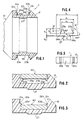
- reference numeral 10 generally designates a bellows-type cover of elastic material such as rubber or plastic material which may be of any known construction.
- the two-tier arrangement provided, for example, at the large end of the bellows-type cover 10 is generally designated by reference numeral 11 which is provided with a circumferentially extending, groove-shaped recess generally designated by reference numeral 20 that provides the two-tier positioning of the clamping member.
- Recess 20 is provided with side walls 21a and 21b spaced in the axial direction from one another a distance c ( Figure 4) slightly greater than the width of the clamping member generally designated by reference numeral 40 .
- the radial depth d is thereby slightly larger than the thickness of the clamping member 40 .
- the radially outer position of the two-tier structure is formed by the at least approximately horizontally extending surfaces 22a and 22b of at least one pair, but preferably several pairs, of yieldable support members 23a and 23b extending toward one another in the recess 20 .
- the lower surfaces 24a and 24b of the members 23a and 23b which are triangularly shaped in cross section extend at an angle downwardly outwardly to the side surfaces 21a and 21b .
- the connection between the top surfaces 22a and 22b and the inclined lower surfaces 24a and 24b are preferably rounded off at 25a and 25b .
- the members 23a and 23b are integral with the larger end 11 of the bellows-type cover 10 and are therefore made of the same elastic material which permits yielding thereof.
- the members 23a and 23b of a pair of members of which preferably several, such as three or four, are distributed uniformly over the circumference of the recess 20 retain the clamping member 40 such as an "Oetiker" puzzle-lock compression ring in the preassembled condition in which the clamping member 40 is securely held integrated with the bellows-type cover 10 because of the self-retaining function of the upper part of the groove-shaped recess 20 disposed radially outwardly of the members 23a and 23b .
- the members 23a and 23b which form protruding lip-like elements, are able to yield to permit the clamping member 40 to enter the radially inward part of the groove-shaped recess 20 in which it is then firmly held in position on the bottom 26 of the groove-shaped recess as a result of the tightening, respectively, shrinking of the diametric dimension thereof.
- the elastic members 23a and 23b are then able to spring back to project again over the radially outer surface of the clamping member 40 in the form indicated in Figure 3 and designated by reference numeral 23a' and 23b' .
- Yieldable support members in the form of elastic lip-like projections extending toward one another which provide a temporary radially outer position of the two-tier arrangement with a completely safe retaining function to achieve the required integration are therefore necessary to assure an assembly of a bellows-type cover with integrated clamping member.
- the external surface 12 of the outer end of the bellows-type cover 10 is thereby inclined to form a rectilinearly obliquely upwardly extending flank to assist in centering and mounting the clamping ring in the groove-shaped recess of the self-retaining arrangement.
- the bellows-type cover 10 is made, for example, of Hytrell® and is to be fastened over a metallic axle stub by means of a shrinkable compression ring such as an "Oetiker" puzzle-type compression ring as disclosed in the two aforementioned U.S. patents.
- the compression ring has a nominal diameter of 88 mm. to be shrunk to a diametric dimension of 85 mm. which corresponds to the diametric dimension of the bottom 26 of the recess 11 .
- the width c of the radially outer portion of the groove-shaped recess 11 delimited by the side walls 21a and 21b is thereby 9.6 mm.
- the axial spacing e between the tips of the lip-like members 23a and 23b is 7.85 mm.
- the radius of curvature of the rounded-off portions 25a and 25b is 0.3 mm.
- the angle of the lower inclined surfaces 24a and 24b with respect to the radial direction is 45°
- the width of the intersection of the surfaces 24a and 24b with the side walls of the recess 11 is 10 mm.
- the overall dimension g of the large end portion of the bellows-type cover is 15 mm.
- the depth d of the groove-shaped recess 20 is 3 mm.
- the depth d' of the recess formed radially outwardly of by the upper support surfaces 22a and 22b is 1.5 mm.
- the overall thickness k of the end section 11 is 4.5 mm. while the radially inwardly extending circumferential projection 27 preferably centered with respect to the recess 11 , has a radially inward extension m of 0.5 mm., and has an axial length l of 5 mm. while the radii of curvature R1 are 0.5 mm.
- the two-tier arrangement may be used with any type of bellows made from any appropriate known elastic material whereby the yieldable support members are designed to provide the required elasticity considering the material used for the bellows-type cover and the need for yieldingness to permit a release of the temporary radially outer position of the integrated clamping member.
- the support members may be arranged in the groove-shaped recess so as to axially face one another pairwise but may also be arranged in staggered relationship so that one member on one side is followed staggered in the circumferential direction by the next member on the other side of the recess and so on.
- the flank surface 12 need not be rectilinear but may also have a curved configuration of any appropriate shape. I therefore do not wish to be limited to the details shown and described herein but intend to cover all such changes and modifications as are encompassed by the scope of the appended claims.
Landscapes
- Engineering & Computer Science (AREA)
- General Engineering & Computer Science (AREA)
- Mechanical Engineering (AREA)
- Diaphragms And Bellows (AREA)
- Clamps And Clips (AREA)
- Protection Of Pipes Against Damage, Friction, And Corrosion (AREA)
- Cooling, Air Intake And Gas Exhaust, And Fuel Tank Arrangements In Propulsion Units (AREA)
Claims (13)
- Elément de recouvrement de type à soufflet pour un élément de serrage pouvant être intégré afin de former un ensemble préassemblé, comprenant un moyen formant évidement (20) en forme de rainure dans l'élément de recouvrement de type à soufflet (10) pour recevoir un élément de serrage (40), ledit moyen formant évidement présentant une surface de fond (26) s'étendant de manière circonférentielle, vers l'intérieur, dans le sens radial en vue de sa mise en prise avec ledit élément de serrage dans la position totalement installée de ce dernier, et d'autres moyens (23a, 23b) pour maintenir ledit élément de serrage (40) dans une position de préassemblage au-dessus de ladite surface de fond,
caractérisé en ce que ledit autre moyen comprend des éléments de support élastiques (23a, 23b) formant un fond provisoire à un certain niveau dans ledit moyen formant évidement (20) entre ladite surface de fond (26) et les limites extérieures dans le sens radial desdits moyens formant évidements, pour maintenir ledit élément de serrage (40) dans la position de préassemblage dans ledit moyen formant évidement (20) de telle sorte qu'il n'entre pas en contact avec la surface de fond (26) dudit moyen formant évidement (20). - Elément de recouvrement selon la revendication 1, selon lequel ledit autre moyen (23a, 23b) peut être utilisé pour libérer le fond provisoire en présence des forces dirigées vers l'intérieur dans le sens radial, pour permettre à l'élément de serrage (40) de se déplacer pour passer de ladite position de préassemblage à la position totalement installée.
- Elément de recouvrement selon la revendication 1 ou 2, selon lequel ledit autre moyen comprend au moins une paire d'éléments de support élastiques (23a, 23b) audit niveau constituant ledit fond provisoire.
- Elément de recouvrement selon la revendication 3, selon lequel plusieurs paires d'éléments de support élastiques (23a, 23b) sont prévues le long de la circonférence dudit moyen formant évidement (20).
- Elément de recouvrement selon la revendication 3, selon lequel une paire d'éléments de support élastiques (23a, 23b) est constituée par une paire de saillies de type lèvres élastiques s'étendant l'une vers l'autre à partir des parois latérales opposées (21a, 21b) dudit moyen formant évidement (20).
- Elément de recouvrement selon la revendication 5, selon lequel lesdites saillies de type lèvres (23a, 23b) présentent approximativement une forme triangulaire en coupe transversale et possèdent une surface supérieure s'étendant de manière sensiblement axiale (22a, 22b) formant ledit fond provisoire, et selon lequel ladite surface supérieure est, de préférence, placée à environ la moitié de la profondeur dudit moyen formant évidement (20).
- Elément de recouvrement selon l'une quelconque des revendications précédentes, présentant une surface externe oblique (12) inclinée vers l'extérieur dans le sens radial en direction dudit moyen formant évidement (20) pour faciliter le montage et le centrage d'un élément de serrage (40) pendant la mise en place dans ledit moyen formant évidement (20).
- Elément de recouvrement selon l'une quelconque des revendications précédentes, comprenant un élément de serrage (40) dans ledit moyen formant évidement (20) comme partie intégrée de celui-ci.
- Ensemble comprenant un moyen formant manchon de type à soufflet (10) et un élément de serrage intégré pré-assemblé (40) adapté pour venir se loger dans un moyen formant évidement (20) en forme de rainure ménagée dans le moyen formant manchon de type à soufflet, et d'autres moyens (23a, 23b) assurant un positionnement en deux étapes de l'élément de serrage (40) dans lequel, dans une première position, l'élément de serrage est intégré avec le moyen formant manchon de type à soufflet (10) correspondant à l'état encore non serré de l'élément de serrage, et dans la deuxième position, l'élément de serrage est dans la position serrée installée,
caractérisé en ce que ledit autre moyen comprend des éléments de support élastiques (23a, 23b) formant un fond provisoire à un certain niveau dans ledit moyen formant évidement (20) entre une surface de fond (26) et les limites extérieures dans le sens radial dudit moyen formant évidement, pour maintenir ledit élément de serrage (40) dans l'état encore non serré dans ledit moyen formant évidement (20) de telle sorte qu'il n'entre pas en contact avec la surface de fond (26) dudit moyen formant évidement (20). - Ensemble selon la revendication 9, selon lequel ledit autre moyen (23a, 23b) peut servir à assurer une action de maintien automatique sur l'élément de serrage (40) dans ladite première position, à une distance radiale sensiblement constante par rapport au moyen formant manchon de type à soufflet (10).
- Ensemble selon la revendication 9 ou la revendication 10, selon lequel ledit autre moyen est formé par des moyens formant saillie s'étendant dans le sens axial (23a, 23b) pour retenir de manière non amovible l'élément de serrage (40) dans ledit moyen formant évidement (20), et selon lequel lesdits moyens formant saillies (23a, 23b) sont élastiques en présence de forces de serrage cherchant à déloger l'élément de serrage pour le faire passer de la première à la deuxième position.
- Ensemble selon la revendication 11, selon lequel lesdits moyens formant saillies (23a, 23b) sont approximativement de forme triangulaire avec une surface supérieure (22a, 22b) sensiblement parallèle à l'axe du moyen formant manchon de type à soufflet et une surface inclinée (24a, 24b) s'étendant depuis la pointe du moyen formant saillie en formant un angle aigu orienté dans le sens radial vers l'intérieur et en direction de la surface latérale (21a, 21 b) du moyen formant évidement (20).
- Ensemble selon l'une quelconque des revendications 9 à 12, selon lequel un côté du moyen formant évidement (20) est formé par une partie du moyen formant manchon de type à soufflet (10) présentant une surface externe inclinée (12) pour faciliter l'installation de l'élément de serrage (40) à intégrer dans le moyen formant manchon de type à soufflet.
Applications Claiming Priority (2)
| Application Number | Priority Date | Filing Date | Title |
|---|---|---|---|
| US1802496P | 1996-05-21 | 1996-05-21 | |
| US18024 | 1996-05-21 |
Publications (2)
| Publication Number | Publication Date |
|---|---|
| EP0809034A1 EP0809034A1 (fr) | 1997-11-26 |
| EP0809034B1 true EP0809034B1 (fr) | 2000-11-02 |
Family
ID=21785834
Family Applications (1)
| Application Number | Title | Priority Date | Filing Date |
|---|---|---|---|
| EP97107390A Expired - Lifetime EP0809034B1 (fr) | 1996-05-21 | 1997-05-05 | Recouvrement à soufflet avec élément de serrage intégré |
Country Status (14)
| Country | Link |
|---|---|
| US (1) | US6224066B1 (fr) |
| EP (1) | EP0809034B1 (fr) |
| JP (1) | JP4068179B2 (fr) |
| KR (1) | KR100509211B1 (fr) |
| CN (1) | CN1083952C (fr) |
| AR (1) | AR007134A1 (fr) |
| AU (1) | AU721244B2 (fr) |
| BR (1) | BR9703220A (fr) |
| CA (1) | CA2204454C (fr) |
| DE (1) | DE69703411T2 (fr) |
| ES (1) | ES2152592T3 (fr) |
| PT (1) | PT809034E (fr) |
| TR (1) | TR199700401A2 (fr) |
| ZA (1) | ZA973959B (fr) |
Families Citing this family (21)
| Publication number | Priority date | Publication date | Assignee | Title |
|---|---|---|---|---|
| PT990811E (pt) | 1998-10-02 | 2003-10-31 | Oetiker Hans Maschinen | Disposicao pre-montada do tipo de fole para revestir eixos articulados |
| EP0990810B1 (fr) * | 1998-10-02 | 2003-05-02 | Hans Oetiker AG Maschinen- und Apparatefabrik | Recouvrement à soufflet |
| US6558262B1 (en) * | 2000-12-22 | 2003-05-06 | Torque-Traction Technologies, Inc. | Boot for slip yoke assembly in a vehicle driveshaft |
| JP2002227870A (ja) * | 2001-01-31 | 2002-08-14 | Keeper Co Ltd | 等速ジョイント用の樹脂製ブーツ |
| DE10249474A1 (de) * | 2002-10-24 | 2004-05-13 | Rasmussen Gmbh | Verbindung einer Schelle mit einem Schlauch zur Vorpositionierung der Schelle |
| DE10305279A1 (de) * | 2003-02-08 | 2004-08-19 | Saurer Gmbh & Co. Kg | Kanalplattenadapter für eine Offenend-Rotorspinnvorrichtung |
| DE10324391B4 (de) * | 2003-05-30 | 2013-02-21 | Contitech Vibration Control Gmbh | Dichtung und Befestigung einer Manschette |
| KR20060061862A (ko) | 2003-10-20 | 2006-06-08 | 가부시키가이샤 도쿠에 | 유니버셜 샤프트 커플링용 부트 |
| JP4729688B2 (ja) | 2004-09-30 | 2011-07-20 | 日本発條株式会社 | 無端式ブーツ固定バンド及びその製造方法 |
| EP1828631B1 (fr) * | 2004-12-21 | 2008-05-28 | GKN Driveline International GmbH | Systeme pour fixer un soufflet sur un element comprenant au moins une partie a lobes |
| US8689953B2 (en) * | 2006-03-22 | 2014-04-08 | Avm Industries | Sealed gas spring cover |
| JP2010001979A (ja) * | 2008-06-20 | 2010-01-07 | Ntn Corp | 等速自在継手 |
| US8973921B2 (en) * | 2010-03-09 | 2015-03-10 | Baker Hughes Incorporated | High temperature/high pressure seal |
| US8640815B2 (en) | 2011-02-10 | 2014-02-04 | Honda Motor Company, Ltd. | Boot assembly |
| WO2015016981A1 (fr) * | 2013-08-01 | 2015-02-05 | Gkn Driveline North America, Inc. | Ensemble d'enveloppe de soufflet à profil surmoulé |
| US20150115547A1 (en) * | 2013-10-24 | 2015-04-30 | Aktiebolaget Skf | Seal with Tabs for Retaining Energizing Member |
| US20180220761A1 (en) * | 2017-02-09 | 2018-08-09 | Kelly F. Jameson | Dual Lid Closure mechanism |
| US11499500B2 (en) * | 2019-06-07 | 2022-11-15 | Caterpillar Inc. | Systems and methods for seal retention |
| US20230191865A1 (en) * | 2021-12-20 | 2023-06-22 | Continental Automotive Systems, Inc. | Airspring gaiter with sliding joint |
| KR102474864B1 (ko) * | 2022-06-03 | 2022-12-06 | 모나스펌프 주식회사 | 조인트 밀봉 구조 |
| JP2024062817A (ja) * | 2022-10-25 | 2024-05-10 | 三桜工業株式会社 | 配管継手 |
Family Cites Families (16)
| Publication number | Priority date | Publication date | Assignee | Title |
|---|---|---|---|---|
| US3447229A (en) * | 1966-12-27 | 1969-06-03 | Nat Lead Co | Method and apparatus for captive washer assembling |
| DE2339838C2 (de) * | 1973-08-07 | 1983-11-17 | Fichtel & Sachs Ag, 8720 Schweinfurt | Befestigung eines elastischen schlauchförmigen Körpers auf einem zylindrischen Bauteil |
| DE3103954A1 (de) * | 1981-02-05 | 1982-09-02 | Lemförder Metallwaren AG, 2844 Lemförde | Kugelgelenk |
| EP0246285A1 (fr) * | 1985-11-27 | 1987-11-25 | FRIES, Stephen | Pince a habits |
| DE3612913C1 (de) | 1986-04-17 | 1987-09-10 | Trw Ehrenreich Gmbh | Dichtungsbalg fuer Kugelgelenke |
| US4786272A (en) | 1987-01-28 | 1988-11-22 | Precision Rubber Products Corporation | Retention of boot on CV joint assembly |
| DE3727871A1 (de) * | 1987-08-21 | 1989-03-02 | Loehr & Bromkamp Gmbh | Dichtungsmanschette |
| DE8804280U1 (fr) * | 1988-03-30 | 1988-10-06 | Continental Aktiengesellschaft, 3000 Hannover, De | |
| US4936811A (en) | 1989-03-20 | 1990-06-26 | Wynn's-Precision, Inc. | Boot assembly for constant velocity joint |
| EP0425864B2 (fr) * | 1989-10-31 | 1997-07-02 | GKN Automotive AG | Soufflet |
| JP2936013B2 (ja) | 1991-01-24 | 1999-08-23 | 曙ブレーキ工業株式会社 | ディスクブレーキ用ピンブーツ |
| US5183351A (en) | 1991-07-23 | 1993-02-02 | Gkn Automotive, Inc. | Boot retainer for a mechanical joint |
| GB2262131B (en) * | 1991-12-03 | 1995-06-14 | Draftex Ind Ltd | Clamping rings |
| DE4413664C2 (de) * | 1993-05-29 | 1996-10-24 | Lemfoerder Metallwaren Ag | Dichtungsbalg für ein Kugelgelenk im Fahrwerk eines Kraftfahrzeugs |
| GB2287073A (en) * | 1994-02-24 | 1995-09-06 | Draftex Ind Ltd | Mounting clamp on protective bellows |
| US5622391A (en) * | 1996-01-16 | 1997-04-22 | The Goodyear Tire & Rubber Company | Hose/clamp assembly |
-
1997
- 1997-05-05 EP EP97107390A patent/EP0809034B1/fr not_active Expired - Lifetime
- 1997-05-05 ES ES97107390T patent/ES2152592T3/es not_active Expired - Lifetime
- 1997-05-05 PT PT97107390T patent/PT809034E/pt unknown
- 1997-05-05 DE DE69703411T patent/DE69703411T2/de not_active Expired - Lifetime
- 1997-05-05 CA CA002204454A patent/CA2204454C/fr not_active Expired - Fee Related
- 1997-05-08 ZA ZA9703959A patent/ZA973959B/xx unknown
- 1997-05-14 AR ARP970102019A patent/AR007134A1/es unknown
- 1997-05-19 CN CN97111411A patent/CN1083952C/zh not_active Expired - Fee Related
- 1997-05-20 JP JP13000697A patent/JP4068179B2/ja not_active Expired - Lifetime
- 1997-05-20 AU AU23523/97A patent/AU721244B2/en not_active Ceased
- 1997-05-21 TR TR97/00401A patent/TR199700401A2/xx unknown
- 1997-05-21 BR BR9703220A patent/BR9703220A/pt not_active IP Right Cessation
- 1997-05-21 KR KR1019970019663A patent/KR100509211B1/ko not_active IP Right Cessation
-
1999
- 1999-08-24 US US09/379,633 patent/US6224066B1/en not_active Expired - Lifetime
Also Published As
| Publication number | Publication date |
|---|---|
| ZA973959B (en) | 1997-11-19 |
| KR100509211B1 (ko) | 2005-10-25 |
| DE69703411D1 (de) | 2000-12-07 |
| KR970075597A (ko) | 1997-12-10 |
| JP4068179B2 (ja) | 2008-03-26 |
| AU721244B2 (en) | 2000-06-29 |
| CA2204454A1 (fr) | 1997-11-21 |
| ES2152592T3 (es) | 2001-02-01 |
| PT809034E (pt) | 2001-03-30 |
| TR199700401A3 (tr) | 1997-12-21 |
| BR9703220A (pt) | 1998-09-01 |
| EP0809034A1 (fr) | 1997-11-26 |
| CN1083952C (zh) | 2002-05-01 |
| JPH1054493A (ja) | 1998-02-24 |
| AU2352397A (en) | 1997-11-27 |
| US6224066B1 (en) | 2001-05-01 |
| CN1170841A (zh) | 1998-01-21 |
| DE69703411T2 (de) | 2001-06-13 |
| TR199700401A2 (xx) | 1997-12-21 |
| CA2204454C (fr) | 2006-01-03 |
| AR007134A1 (es) | 1999-10-13 |
| MX9703706A (es) | 1998-06-30 |
Similar Documents
| Publication | Publication Date | Title |
|---|---|---|
| EP0809034B1 (fr) | Recouvrement à soufflet avec élément de serrage intégré | |
| EP0990810B1 (fr) | Recouvrement à soufflet | |
| US6089574A (en) | Boot with insertable bushing | |
| CA2176855A1 (fr) | Raccord flexible pour tuyau | |
| US7093808B2 (en) | Clamp holder | |
| GB2186037A (en) | Boot seals | |
| US4516957A (en) | Tripot joint with spider retainer | |
| EP0545629A2 (fr) | Anneaux de serrage | |
| EP0672848A1 (fr) | Soufflets de protection | |
| JP2002526727A5 (fr) | ||
| MXPA97003706A (en) | Cover type of bellows with integr fixed member | |
| JPH07269708A (ja) | 保護ベローズ | |
| EP0887582B1 (fr) | Dispositif de montage préliminaire d'un collier de serrage sur un tuyau souple | |
| JP3977975B2 (ja) | 等速自在継手 | |
| GB2201223A (en) | Friction couplings | |
| JPH04122821U (ja) | 等速ジヨイントブーツ | |
| EP0312317A2 (fr) | Raccord de tuyaux | |
| GB2196403A (en) | Improvements in or relating to pipe fittings | |
| JPH056219U (ja) | ボールジヨイント | |
| JPH07239081A (ja) | ホ−スクランプおよびこれを用いたホ−ス接続装置 | |
| KR19980030208U (ko) | 자동차의 부트 | |
| JPH0814452A (ja) | 管内リング体の保持具 |
Legal Events
| Date | Code | Title | Description |
|---|---|---|---|
| PUAI | Public reference made under article 153(3) epc to a published international application that has entered the european phase |
Free format text: ORIGINAL CODE: 0009012 |
|
| AK | Designated contracting states |
Kind code of ref document: A1 Designated state(s): BE CH DE ES FR GB IT LI NL PT SE |
|
| 17P | Request for examination filed |
Effective date: 19980526 |
|
| 17Q | First examination report despatched |
Effective date: 19981001 |
|
| GRAG | Despatch of communication of intention to grant |
Free format text: ORIGINAL CODE: EPIDOS AGRA |
|
| GRAG | Despatch of communication of intention to grant |
Free format text: ORIGINAL CODE: EPIDOS AGRA |
|
| GRAG | Despatch of communication of intention to grant |
Free format text: ORIGINAL CODE: EPIDOS AGRA |
|
| GRAH | Despatch of communication of intention to grant a patent |
Free format text: ORIGINAL CODE: EPIDOS IGRA |
|
| GRAH | Despatch of communication of intention to grant a patent |
Free format text: ORIGINAL CODE: EPIDOS IGRA |
|
| GRAA | (expected) grant |
Free format text: ORIGINAL CODE: 0009210 |
|
| ITF | It: translation for a ep patent filed |
Owner name: BARZANO' E ZANARDO ROMA S.P.A. |
|
| AK | Designated contracting states |
Kind code of ref document: B1 Designated state(s): BE CH DE ES FR GB IT LI NL PT SE |
|
| REG | Reference to a national code |
Ref country code: CH Ref legal event code: NV Representative=s name: TROESCH SCHEIDEGGER WERNER AG Ref country code: CH Ref legal event code: EP |
|
| REF | Corresponds to: |
Ref document number: 69703411 Country of ref document: DE Date of ref document: 20001207 |
|
| REG | Reference to a national code |
Ref country code: ES Ref legal event code: FG2A Ref document number: 2152592 Country of ref document: ES Kind code of ref document: T3 |
|
| ET | Fr: translation filed | ||
| REG | Reference to a national code |
Ref country code: PT Ref legal event code: SC4A Free format text: AVAILABILITY OF NATIONAL TRANSLATION Effective date: 20001227 |
|
| PLBE | No opposition filed within time limit |
Free format text: ORIGINAL CODE: 0009261 |
|
| STAA | Information on the status of an ep patent application or granted ep patent |
Free format text: STATUS: NO OPPOSITION FILED WITHIN TIME LIMIT |
|
| 26N | No opposition filed | ||
| REG | Reference to a national code |
Ref country code: GB Ref legal event code: IF02 |
|
| PGFP | Annual fee paid to national office [announced via postgrant information from national office to epo] |
Ref country code: GB Payment date: 20140528 Year of fee payment: 18 |
|
| PGFP | Annual fee paid to national office [announced via postgrant information from national office to epo] |
Ref country code: CH Payment date: 20140526 Year of fee payment: 18 Ref country code: SE Payment date: 20140526 Year of fee payment: 18 Ref country code: NL Payment date: 20140510 Year of fee payment: 18 Ref country code: PT Payment date: 20140502 Year of fee payment: 18 |
|
| PGFP | Annual fee paid to national office [announced via postgrant information from national office to epo] |
Ref country code: BE Payment date: 20140513 Year of fee payment: 18 |
|
| REG | Reference to a national code |
Ref country code: DE Ref legal event code: R082 Ref document number: 69703411 Country of ref document: DE Representative=s name: PATENTANWAELTE STREHL, SCHUEBEL-HOPF & PARTNER, DE |
|
| REG | Reference to a national code |
Ref country code: CH Ref legal event code: PFA Owner name: OETIKER SCHWEIZ AG, CH Free format text: FORMER OWNER: HANS OETIKER AG MASCHINEN- UND APPARATEFABRIK, CH |
|
| REG | Reference to a national code |
Ref country code: DE Ref legal event code: R082 Ref document number: 69703411 Country of ref document: DE Representative=s name: STREHL SCHUEBEL-HOPF & PARTNER MBB PATENTANWAE, DE Effective date: 20150513 Ref country code: DE Ref legal event code: R082 Ref document number: 69703411 Country of ref document: DE Representative=s name: PATENTANWAELTE STREHL, SCHUEBEL-HOPF & PARTNER, DE Effective date: 20150513 Ref country code: DE Ref legal event code: R081 Ref document number: 69703411 Country of ref document: DE Owner name: OETIKER SCHWEIZ AG, CH Free format text: FORMER OWNER: HANS OETIKER AG MASCHINEN- UND APPARATEFABRIK, HORGEN, CH Effective date: 20150513 |
|
| PGFP | Annual fee paid to national office [announced via postgrant information from national office to epo] |
Ref country code: ES Payment date: 20150413 Year of fee payment: 19 |
|
| REG | Reference to a national code |
Ref country code: ES Ref legal event code: PC2A Owner name: OETIKER SCHWEIZ AG Effective date: 20150810 |
|
| REG | Reference to a national code |
Ref country code: FR Ref legal event code: CD Owner name: OETIKER SCHWEIZ AG, CH Effective date: 20150828 Ref country code: FR Ref legal event code: CA Effective date: 20150828 |
|
| REG | Reference to a national code |
Ref country code: PT Ref legal event code: MM4A Free format text: LAPSE DUE TO NON-PAYMENT OF FEES Effective date: 20151105 |
|
| REG | Reference to a national code |
Ref country code: CH Ref legal event code: PL |
|
| GBPC | Gb: european patent ceased through non-payment of renewal fee |
Effective date: 20150505 |
|
| PG25 | Lapsed in a contracting state [announced via postgrant information from national office to epo] |
Ref country code: CH Free format text: LAPSE BECAUSE OF NON-PAYMENT OF DUE FEES Effective date: 20150531 Ref country code: LI Free format text: LAPSE BECAUSE OF NON-PAYMENT OF DUE FEES Effective date: 20150531 |
|
| REG | Reference to a national code |
Ref country code: NL Ref legal event code: MM Effective date: 20150601 |
|
| PG25 | Lapsed in a contracting state [announced via postgrant information from national office to epo] |
Ref country code: SE Free format text: LAPSE BECAUSE OF NON-PAYMENT OF DUE FEES Effective date: 20150506 Ref country code: PT Free format text: LAPSE BECAUSE OF NON-PAYMENT OF DUE FEES Effective date: 20151105 |
|
| PG25 | Lapsed in a contracting state [announced via postgrant information from national office to epo] |
Ref country code: NL Free format text: LAPSE BECAUSE OF NON-PAYMENT OF DUE FEES Effective date: 20150601 Ref country code: GB Free format text: LAPSE BECAUSE OF NON-PAYMENT OF DUE FEES Effective date: 20150505 |
|
| REG | Reference to a national code |
Ref country code: FR Ref legal event code: PLFP Year of fee payment: 20 |
|
| PGFP | Annual fee paid to national office [announced via postgrant information from national office to epo] |
Ref country code: IT Payment date: 20160524 Year of fee payment: 20 Ref country code: FR Payment date: 20160530 Year of fee payment: 20 |
|
| PGFP | Annual fee paid to national office [announced via postgrant information from national office to epo] |
Ref country code: DE Payment date: 20160726 Year of fee payment: 20 |
|
| REG | Reference to a national code |
Ref country code: DE Ref legal event code: R071 Ref document number: 69703411 Country of ref document: DE |
|
| PG25 | Lapsed in a contracting state [announced via postgrant information from national office to epo] |
Ref country code: BE Free format text: LAPSE BECAUSE OF NON-PAYMENT OF DUE FEES Effective date: 20150531 |
|
| REG | Reference to a national code |
Ref country code: ES Ref legal event code: FD2A Effective date: 20180507 |
|
| PG25 | Lapsed in a contracting state [announced via postgrant information from national office to epo] |
Ref country code: ES Free format text: LAPSE BECAUSE OF NON-PAYMENT OF DUE FEES Effective date: 20160506 |