EP0809006B1 - Appareil de commande de l'air d'admission - Google Patents
Appareil de commande de l'air d'admission Download PDFInfo
- Publication number
- EP0809006B1 EP0809006B1 EP97108413A EP97108413A EP0809006B1 EP 0809006 B1 EP0809006 B1 EP 0809006B1 EP 97108413 A EP97108413 A EP 97108413A EP 97108413 A EP97108413 A EP 97108413A EP 0809006 B1 EP0809006 B1 EP 0809006B1
- Authority
- EP
- European Patent Office
- Prior art keywords
- valve
- opening
- pressure
- lutrg
- control value
- Prior art date
- Legal status (The legal status is an assumption and is not a legal conclusion. Google has not performed a legal analysis and makes no representation as to the accuracy of the status listed.)
- Expired - Lifetime
Links
- 238000002485 combustion reaction Methods 0.000 claims description 17
- 238000011144 upstream manufacturing Methods 0.000 claims description 6
- 239000000446 fuel Substances 0.000 description 22
- 238000002347 injection Methods 0.000 description 18
- 239000007924 injection Substances 0.000 description 18
- 230000003247 decreasing effect Effects 0.000 description 15
- 230000000875 corresponding effect Effects 0.000 description 13
- 230000008859 change Effects 0.000 description 11
- 230000001276 controlling effect Effects 0.000 description 11
- 230000004044 response Effects 0.000 description 9
- 230000006870 function Effects 0.000 description 8
- 238000000034 method Methods 0.000 description 7
- 230000008569 process Effects 0.000 description 7
- 230000007423 decrease Effects 0.000 description 6
- 230000010354 integration Effects 0.000 description 6
- 238000010276 construction Methods 0.000 description 3
- 230000001934 delay Effects 0.000 description 3
- 230000004043 responsiveness Effects 0.000 description 3
- 238000010586 diagram Methods 0.000 description 2
- 239000000203 mixture Substances 0.000 description 2
- 230000001105 regulatory effect Effects 0.000 description 2
- 239000000779 smoke Substances 0.000 description 2
- 238000013459 approach Methods 0.000 description 1
- 239000000872 buffer Substances 0.000 description 1
- 230000006835 compression Effects 0.000 description 1
- 238000007906 compression Methods 0.000 description 1
- 230000002596 correlated effect Effects 0.000 description 1
- 238000007599 discharging Methods 0.000 description 1
- 239000000428 dust Substances 0.000 description 1
- 238000002474 experimental method Methods 0.000 description 1
- 239000002828 fuel tank Substances 0.000 description 1
- 230000007257 malfunction Effects 0.000 description 1
- 239000007787 solid Substances 0.000 description 1
Images


Classifications
-
- F—MECHANICAL ENGINEERING; LIGHTING; HEATING; WEAPONS; BLASTING
- F02—COMBUSTION ENGINES; HOT-GAS OR COMBUSTION-PRODUCT ENGINE PLANTS
- F02D—CONTROLLING COMBUSTION ENGINES
- F02D11/00—Arrangements for, or adaptations to, non-automatic engine control initiation means, e.g. operator initiated
- F02D11/06—Arrangements for, or adaptations to, non-automatic engine control initiation means, e.g. operator initiated characterised by non-mechanical control linkages, e.g. fluid control linkages or by control linkages with power drive or assistance
- F02D11/10—Arrangements for, or adaptations to, non-automatic engine control initiation means, e.g. operator initiated characterised by non-mechanical control linkages, e.g. fluid control linkages or by control linkages with power drive or assistance of the electric type
- F02D11/105—Arrangements for, or adaptations to, non-automatic engine control initiation means, e.g. operator initiated characterised by non-mechanical control linkages, e.g. fluid control linkages or by control linkages with power drive or assistance of the electric type characterised by the function converting demand to actuation, e.g. a map indicating relations between an accelerator pedal position and throttle valve opening or target engine torque
-
- F—MECHANICAL ENGINEERING; LIGHTING; HEATING; WEAPONS; BLASTING
- F02—COMBUSTION ENGINES; HOT-GAS OR COMBUSTION-PRODUCT ENGINE PLANTS
- F02D—CONTROLLING COMBUSTION ENGINES
- F02D11/00—Arrangements for, or adaptations to, non-automatic engine control initiation means, e.g. operator initiated
- F02D11/06—Arrangements for, or adaptations to, non-automatic engine control initiation means, e.g. operator initiated characterised by non-mechanical control linkages, e.g. fluid control linkages or by control linkages with power drive or assistance
- F02D11/08—Arrangements for, or adaptations to, non-automatic engine control initiation means, e.g. operator initiated characterised by non-mechanical control linkages, e.g. fluid control linkages or by control linkages with power drive or assistance of the pneumatic type
-
- F—MECHANICAL ENGINEERING; LIGHTING; HEATING; WEAPONS; BLASTING
- F02—COMBUSTION ENGINES; HOT-GAS OR COMBUSTION-PRODUCT ENGINE PLANTS
- F02B—INTERNAL-COMBUSTION PISTON ENGINES; COMBUSTION ENGINES IN GENERAL
- F02B3/00—Engines characterised by air compression and subsequent fuel addition
- F02B3/06—Engines characterised by air compression and subsequent fuel addition with compression ignition
-
- F—MECHANICAL ENGINEERING; LIGHTING; HEATING; WEAPONS; BLASTING
- F02—COMBUSTION ENGINES; HOT-GAS OR COMBUSTION-PRODUCT ENGINE PLANTS
- F02D—CONTROLLING COMBUSTION ENGINES
- F02D41/00—Electrical control of supply of combustible mixture or its constituents
- F02D41/0002—Controlling intake air
- F02D2041/0022—Controlling intake air for diesel engines by throttle control
-
- Y—GENERAL TAGGING OF NEW TECHNOLOGICAL DEVELOPMENTS; GENERAL TAGGING OF CROSS-SECTIONAL TECHNOLOGIES SPANNING OVER SEVERAL SECTIONS OF THE IPC; TECHNICAL SUBJECTS COVERED BY FORMER USPC CROSS-REFERENCE ART COLLECTIONS [XRACs] AND DIGESTS
- Y02—TECHNOLOGIES OR APPLICATIONS FOR MITIGATION OR ADAPTATION AGAINST CLIMATE CHANGE
- Y02T—CLIMATE CHANGE MITIGATION TECHNOLOGIES RELATED TO TRANSPORTATION
- Y02T10/00—Road transport of goods or passengers
- Y02T10/10—Internal combustion engine [ICE] based vehicles
- Y02T10/40—Engine management systems
Definitions
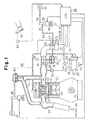
- the valve 25 includes a shaft 25a, which is rotatably supported by the wall of the passage 16. One end of the shaft 25a protrudes from the outer surface of the passage 16. A link 25b is fixed to the protruding end of the shaft 25a. The distal end of the link 25b is connected to the distal end of the rod 26a.
- the pressure chamber 30 is connected to a vacuum pump 32 via a vacuum passage 33.
- a first electric vacuum regulating valve (EVRV) 34 is located in the passage 33.
- the EVRV 34 is an electromagnetic cross valve having three ports 35, 36 and 38.
- the output port 35 communicates with the pressure chamber 30 of the actuator 26 by the passage 33.
- the negative pressure port 36 communicates with the vacuum pump 32.
- the atmospheric air port 38 communicates with the atmospheric air via a filter 37.
- the filter 37 prevents dust and mud from entering the first EVRV 34 through the atmospheric air port 38.
- the fuel injection pump 18 is a known distribution type and supplies fuel to each injection nozzle 17 through the fuel line 19. The fuel is then combusted in each combustion chamber 12. Specifically, the injection pump 18 compresses fuel from a fuel tank (not shown) to a highly pressurized state and supplies a predetermined amount of the pressurized fuel to the individual injection nozzles 17 at a predetermined timing. Each injection nozzle 17 operates based on the pressure of the supplied fuel and injects the fuel to the associated combustion chamber 12.
- the injection pump 18 has an electromagnetic spill valve 54 and a timer 55.
- the spill valve 54 adjusts the amount of fuel to be pumped out from the pump 18.
- the timer 55 controls the start timing of the fuel discharge from the pump 18, that is, the timer 55 adjusts the times at which fuel is injected from each injection nozzle 17.
- the spill valve 54 and the timer 55 are electrically controlled by the ECU 39.
- a restriction valve sensor 58 is provided in the vicinity of the restriction valve 25.
- the sensor 58 detects the actual opening LUACT of the valve 25 and issues a signal corresponding to the actual opening LUACT.
- the ECU 39 receives signals transmitted from the sensors 56 to 59, 61 and 62.
- the structure of the ECU 39 will now be described with reference.to the block diagram of Fig. 3.
- the ECU 39 includes a central processing unit (CPU) 70, a read only memory (ROM) 71, a random access memory (RAM) 72, and a backup RAM 73.
- the ROM 71 previously stores predetermined control programs.
- the RAM 72 temporarily stores the results of computations performed by the CPU 70.
- the backup RAM 73 retains prestored data.
- the ECU 39 further includes an input port 74 and an output port 75.
- the CPU 70, the ROM 71, the RAM 72, the backup RAM 73, the input port 74 and the output port 75 are connected one another by a bus 76.
- the electromagnetic spill valve 54, the timer 55, the first EVRV 34 and the second EVRV 48 are connected to the output port 75 by drivers 81.
- the CPU 70 controls the valve 54, the timer 55 and the EVRVs 34, 48 based on the signals from the sensors 56 to 59, 61 and 62, thereby performing fuel injection control, restriction valve opening control and EGR control.
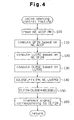
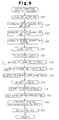
- a routine for controlling the opening of the intake air restriction valve 25 (valve opening control routine) will now be described with reference to the flowchart of Fig. 4.
- the CPU 70 periodically performs the routine at predetermined intervals.
- step 110 the CPU 70 computes a amount QFIN of fuel injection in accordance with the engine speed NE and the pedal depression amount ACCP based on function data previously stored in the ROM 71.
- step 120 the CPU 70 computes a target opening LUTRG of the valve 25 in accordance with the injection amount QFIN and the engine speed NE based on function data previously stored in the ROM 71.
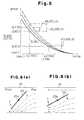
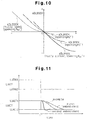
- step 130 the CPU 70 computes a basic control value DLBSE in accordance with the target opening LUTRG based on function data shown in the graph of Fig. 5.
- the function data is previously stored in the ROM 71.
- the solid line in the graph shows the relationship between the target opening LUTRG of the valve 25 and the basic control value DLBSE. In computation of DLBSE, the force of intake air pressure acting on the valve 25 is not taken into consideration.
- the value DLBSE is used to determine the magnitude of force produced by the negative pressure introduced into the chamber 30 of the actuator 26.
- DLBSE corresponds to duty ratio of signals transmitted to the first EVRV 34.
- the magnitude of the negative pressure is determined in accordance with the duty ratio.
- the force acts on the rod 26a and determines the opening of the valve 25 in relation with the force of the spring 31. That is, the value DLBSE corresponds to the magnitude of force produced by the negative pressure.
- DLBSE decreases as the target opening LUTRG increases. The relationship between LUTRG and DLBSE is previously determined through experiments.
- step 160 the CPU 70 transmits a signal, which has a duty ratio corresponding to the final control value DLFIN, to the first EVRV 34.
- the CPU 70 thus controls the magnitude of the force produced by negative pressure introduced in the pressure chamber 30, thereby matching the actual opening LUACT of the restriction valve 25 with the target opening LUTRG.
- the CPU then temporarily suspends the current routine.
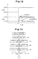
- Fig. 9 shows a valve opening control routine according to the second embodiment. In the steps having the same numerals as those in the routine of Fig. 4, the same process is performed as in the first embodiment.
- step 132 the CPU 70 computes a difference DLU between a target opening LUTRG and the actual opening LUACT.
Landscapes
- Engineering & Computer Science (AREA)
- Chemical & Material Sciences (AREA)
- Combustion & Propulsion (AREA)
- Mechanical Engineering (AREA)
- General Engineering & Computer Science (AREA)
- Electrical Control Of Air Or Fuel Supplied To Internal-Combustion Engine (AREA)
- Control Of Throttle Valves Provided In The Intake System Or In The Exhaust System (AREA)
- Output Control And Ontrol Of Special Type Engine (AREA)
Claims (6)
- Appareil destiné à commander l'air d'admission dans un moteur à combustion (11), ledit moteur (11) comportant un passage d'admission d'air (16) et un clapet (25) dans le passage d'admission d'air (16), ledit clapet (25) étant accouplé à une pédale d'accélérateur (60) et à un actionneur (26), dans lequel l'ouverture dudit clapet (25) varie jusqu'à une ouverture cible (LUTRG) pour régler la quantité d'air d'admission s'écoulant dans le passage d'admission d'air (16) vers le moteur (11), ladite ouverture cible (LUTRG) étant calculée sur la base du fonctionnement de la pédale d'accélérateur (60) et de l'état d'entraínement du moteur (11), dans lequel ladite ouverture de clapet dévie pour une ouverture déviée du fait de la pression de l'air d'admission appliquée au clapet (25), ledit appareil étant
caractérisé par
des moyens (26, 34, 39) destinés à compenser ladite déviation de l'ouverture du clapet (25) en calculant une valeur de la commande de base hypothétique (DLBSE) basée sur ladite ouverture cible (LUTRG) et une valeur de correction (ΔDLBSEJ) basée sur une pression différentielle en aval et en amont du clapet (25) dans le passage d'admission d'air (16), ladite valeur de correction (ΔDLBSEJ) corrigeant ladite valeur de la commande de base hypothétique (DLBSE). - Appareil selon la revendication 1, caractérisé en ce que ledit clapet inclut un clapet d'étranglement (25) disposé de façon rotative dans le passage d'admission d'air (16) et en ce que ledit clapet (25) tend à tourner sur la base de la pression de l'air d'admission provoquant la déviation de son ouverture.
- Appareil selon la revendication 2, caractérisé en ce que lesdits moyens (39) calculent une valeur de re-correction (ΔDLBSEK) qui annule sensiblement la force indésirable agissant sur le clapet (25).
- Appareil selon les revendications 4 ou 5,
caractérisé en ce que ladite valeur de correction (ΔDLBSEK) augmente en proportion de la vitesse du moteur (NE) et en proportion de la pression de l'air d'admission. - Appareil selon l'une quelconque des revendications 1 à 4, caractérisé en ce que lesdits moyens de calcul comprennent une unité de commande électrique (26) délivrant en sortie un signal de service comportant des validations basées sur l'amplitude calculée.
- Appareil selon la revendication 5, caractérisé en ce que lesdits moyens de compensation comprennent de plus une paire de chambres adjacentes entre elles au moyen d'un diaphragme (27), une tige (26a) reliant le clapet (25) au diaphragme (27), une électrovanne (34) actionnée par le signal de service et raccordant sélectivement à une source de pression négative (32) et à une source de pression positive.
Applications Claiming Priority (3)
| Application Number | Priority Date | Filing Date | Title |
|---|---|---|---|
| JP1300/96 | 1996-05-24 | ||
| JP130096 | 1996-05-24 | ||
| JP13009696A JP3189680B2 (ja) | 1996-05-24 | 1996-05-24 | 内燃機関の吸気制御装置 |
Publications (3)
| Publication Number | Publication Date |
|---|---|
| EP0809006A2 EP0809006A2 (fr) | 1997-11-26 |
| EP0809006A3 EP0809006A3 (fr) | 2000-07-26 |
| EP0809006B1 true EP0809006B1 (fr) | 2004-03-24 |
Family
ID=15025866
Family Applications (1)
| Application Number | Title | Priority Date | Filing Date |
|---|---|---|---|
| EP97108413A Expired - Lifetime EP0809006B1 (fr) | 1996-05-24 | 1997-05-23 | Appareil de commande de l'air d'admission |
Country Status (3)
| Country | Link |
|---|---|
| EP (1) | EP0809006B1 (fr) |
| JP (1) | JP3189680B2 (fr) |
| DE (1) | DE69728209T2 (fr) |
Families Citing this family (2)
| Publication number | Priority date | Publication date | Assignee | Title |
|---|---|---|---|---|
| US8364373B2 (en) * | 2010-08-30 | 2013-01-29 | GM Global Technology Operations LLC | Method for controlling internal combustion engines in hybrid powertrains |
| CN110953075A (zh) * | 2019-11-28 | 2020-04-03 | 中汽研汽车检验中心(昆明)有限公司 | 一种精确控制汽车发动机进气口压差的方法 |
Family Cites Families (4)
| Publication number | Priority date | Publication date | Assignee | Title |
|---|---|---|---|---|
| US4342299A (en) * | 1980-09-15 | 1982-08-03 | General Motors Corporation | Throttle positioning system |
| DE3380036D1 (en) * | 1982-12-13 | 1989-07-13 | Mikuni Kogyo Kk | Method for controlling an air flow quantity |
| JPS59206632A (ja) * | 1983-05-05 | 1984-11-22 | Mikuni Kogyo Co Ltd | 内燃機関混合気供給方法及び装置 |
| GB2216596B (en) * | 1988-03-15 | 1992-09-09 | Alexander Robertson | Control device for diesel engines |
-
1996
- 1996-05-24 JP JP13009696A patent/JP3189680B2/ja not_active Expired - Fee Related
-
1997
- 1997-05-23 DE DE69728209T patent/DE69728209T2/de not_active Expired - Lifetime
- 1997-05-23 EP EP97108413A patent/EP0809006B1/fr not_active Expired - Lifetime
Also Published As
| Publication number | Publication date |
|---|---|
| JPH09317501A (ja) | 1997-12-09 |
| JP3189680B2 (ja) | 2001-07-16 |
| DE69728209T2 (de) | 2006-07-20 |
| EP0809006A2 (fr) | 1997-11-26 |
| EP0809006A3 (fr) | 2000-07-26 |
| DE69728209D1 (de) | 2004-04-29 |
Similar Documents
| Publication | Publication Date | Title |
|---|---|---|
| US6016788A (en) | Fuel injection control system for a diesel engine | |
| US5878711A (en) | Control apparatus for a cylinder-injection spark-ignition internal combustion engine | |
| US5704340A (en) | Excess air rate detecting apparatus and an excess air rate control apparatus for an engine | |
| US7150264B2 (en) | Control device for internal combustion engine | |
| EP0735245B1 (fr) | Dispositif de commande du calage de soupapes pour moteurs à combustion interne | |
| EP1178192B1 (fr) | Dispositif de commande de la presssion de suralimentation dans un moteur à combustion interne | |
| US6779508B2 (en) | Control system of internal combustion engine | |
| US5806497A (en) | Method of and apparatus for controlling fuel injection of internal combustion engine | |
| JP3700051B2 (ja) | 内燃機関の吸気制御装置 | |
| US6378501B1 (en) | Device for controlling the fuel pressure in a direct cylinder fuel injection engine | |
| US6502546B2 (en) | Intake air control system of engine | |
| KR100645940B1 (ko) | 직접분사엔진의제어기 | |
| EP0809006B1 (fr) | Appareil de commande de l'air d'admission | |
| EP0809009B1 (fr) | Appareil de régulation pour moteur diesel | |
| JP3551697B2 (ja) | ディーゼルエンジンの制御装置 | |
| JPH0763124A (ja) | 内燃機関の制御方法および制御装置 | |
| JP2000054917A (ja) | Egrバルブの制御装置 | |
| EP1234970A2 (fr) | Commande d'injection de carburant pour moteur à combustion interne | |
| JP3767063B2 (ja) | 内燃機関の空燃比制御装置 | |
| EP0745762B1 (fr) | Système de recirculation de gaz d'échappement pour moteur | |
| JPH08210195A (ja) | ディーゼル機関の排気還流制御装置 | |
| EP3075991B1 (fr) | Dispositif de contrôle pour moteur à combustion interne | |
| JP3909621B2 (ja) | エンジン回転数制御装置 | |
| JP2858284B2 (ja) | 内燃機関の燃料供給制御装置 | |
| JP2858285B2 (ja) | 内燃機関の燃料供給制御装置 |
Legal Events
| Date | Code | Title | Description |
|---|---|---|---|
| PUAI | Public reference made under article 153(3) epc to a published international application that has entered the european phase |
Free format text: ORIGINAL CODE: 0009012 |
|
| 17P | Request for examination filed |
Effective date: 19970523 |
|
| AK | Designated contracting states |
Kind code of ref document: A2 Designated state(s): DE FR GB |
|
| PUAL | Search report despatched |
Free format text: ORIGINAL CODE: 0009013 |
|
| AK | Designated contracting states |
Kind code of ref document: A3 Designated state(s): DE FR GB |
|
| 17Q | First examination report despatched |
Effective date: 20030408 |
|
| GRAP | Despatch of communication of intention to grant a patent |
Free format text: ORIGINAL CODE: EPIDOSNIGR1 |
|
| GRAS | Grant fee paid |
Free format text: ORIGINAL CODE: EPIDOSNIGR3 |
|
| GRAA | (expected) grant |
Free format text: ORIGINAL CODE: 0009210 |
|
| AK | Designated contracting states |
Kind code of ref document: B1 Designated state(s): DE FR GB |
|
| REG | Reference to a national code |
Ref country code: GB Ref legal event code: FG4D |
|
| REF | Corresponds to: |
Ref document number: 69728209 Country of ref document: DE Date of ref document: 20040429 Kind code of ref document: P |
|
| ET | Fr: translation filed | ||
| PLBE | No opposition filed within time limit |
Free format text: ORIGINAL CODE: 0009261 |
|
| STAA | Information on the status of an ep patent application or granted ep patent |
Free format text: STATUS: NO OPPOSITION FILED WITHIN TIME LIMIT |
|
| 26N | No opposition filed |
Effective date: 20041228 |
|
| PGFP | Annual fee paid to national office [announced via postgrant information from national office to epo] |
Ref country code: FR Payment date: 20110523 Year of fee payment: 15 |
|
| PGFP | Annual fee paid to national office [announced via postgrant information from national office to epo] |
Ref country code: GB Payment date: 20110518 Year of fee payment: 15 |
|
| PGFP | Annual fee paid to national office [announced via postgrant information from national office to epo] |
Ref country code: DE Payment date: 20110518 Year of fee payment: 15 |
|
| GBPC | Gb: european patent ceased through non-payment of renewal fee |
Effective date: 20120523 |
|
| REG | Reference to a national code |
Ref country code: FR Ref legal event code: ST Effective date: 20130131 |
|
| REG | Reference to a national code |
Ref country code: DE Ref legal event code: R119 Ref document number: 69728209 Country of ref document: DE Effective date: 20121201 |
|
| PG25 | Lapsed in a contracting state [announced via postgrant information from national office to epo] |
Ref country code: FR Free format text: LAPSE BECAUSE OF NON-PAYMENT OF DUE FEES Effective date: 20120531 Ref country code: GB Free format text: LAPSE BECAUSE OF NON-PAYMENT OF DUE FEES Effective date: 20120523 |
|
| PG25 | Lapsed in a contracting state [announced via postgrant information from national office to epo] |
Ref country code: DE Free format text: LAPSE BECAUSE OF FAILURE TO SUBMIT A TRANSLATION OF THE DESCRIPTION OR TO PAY THE FEE WITHIN THE PRESCRIBED TIME-LIMIT Effective date: 20121201 |