EP0808664A2 - Elektrostatische Pulver-Beschichtungspistole - Google Patents
Elektrostatische Pulver-Beschichtungspistole Download PDFInfo
- Publication number
- EP0808664A2 EP0808664A2 EP97106822A EP97106822A EP0808664A2 EP 0808664 A2 EP0808664 A2 EP 0808664A2 EP 97106822 A EP97106822 A EP 97106822A EP 97106822 A EP97106822 A EP 97106822A EP 0808664 A2 EP0808664 A2 EP 0808664A2
- Authority
- EP
- European Patent Office
- Prior art keywords
- powder paint
- linear elements
- transportation path
- powder
- coating gun
- Prior art date
- Legal status (The legal status is an assumption and is not a legal conclusion. Google has not performed a legal analysis and makes no representation as to the accuracy of the status listed.)
- Withdrawn
Links
Images









Classifications
-
- B—PERFORMING OPERATIONS; TRANSPORTING
- B05—SPRAYING OR ATOMISING IN GENERAL; APPLYING FLUENT MATERIALS TO SURFACES, IN GENERAL
- B05B—SPRAYING APPARATUS; ATOMISING APPARATUS; NOZZLES
- B05B5/00—Electrostatic spraying apparatus; Spraying apparatus with means for charging the spray electrically; Apparatus for spraying liquids or other fluent materials by other electric means
- B05B5/025—Discharge apparatus, e.g. electrostatic spray guns
- B05B5/047—Discharge apparatus, e.g. electrostatic spray guns using tribo-charging
Definitions
- the present invention relates to an electrostatic powder coating gun for charging powder paint used for electrostatic powder coating.
- the electrostatic powder coating is one of the methods of powder coating. It uses powder paint positively or negatively charged to form coating film on the earthed subject of coating by blowing the powder paint.
- a powder coating gun such as a corona gun or triboelectric gun is used to charge and blow the powder paint.
- the corona gun applies high voltage, for example, 70 to 100 KV, to corona electrodes arranged at the exit of the powder paint by using a high-voltage generator, to achieve corona discharge from the electrodes.
- high voltage for example, 70 to 100 KV
- the powder paint which is transporting by pressurized air is charged.
- the charged powder paint thus travels in the electric field formed between the corona gun and the subject of coating, and then adheres to the subject of coating to form the coating film.
- Another conventional triboelectric gun which has a large number of bent thin tubes, uses the inside of the tubes as a powder paint transportation path (Japanese Patent Laid-Open HEI No. 7-874).
- This arrangement provides an increased inner face area around the transportation path to increase the chance of contact between the inner face of the transportation path and particles of the powder paint, so that the charge efficiency is improved.
- a rotary blade is provided in the transportation path of the powder paint (Japanese Patent Laid-Open HEI No. 7-24366). This arrangement rotates the powder paint to increase the chance of contact between the inner surface of the transportation path and the particles of the powder paint to improve the charge efficiency.
- the coating film has recently been required to be as thin as about 25 to 40 ⁇ m, while the coating film thickness required is about 100 to 300 ⁇ m in conventional powder coating. It is therefore necessary to reduce the mean diameter of the particles constituting the powder paint from about 30-40 ⁇ m (conventional) to about 10-20 ⁇ m. As the particle diameter decreases, the specific surface increases dramatically. In this case, it is difficult to give a sufficient chance of contact between the transportation face and the particles, in the conventional triboelectric guns, resulting in significantly reduced charge efficiency. As a result, the maximum blowing capacity decreases further, coating efficiency decreases further, and coating is difficult when the subject of coating has a great surface area.
- the present invention is directed to provide an electrostatic powder coating gun capable of resolving the above-described problems.
- the electrostatic powder coating gun of the present invention comprises a transportation path for powder paint, and a plurality of linear elements or a meshed element arranged in the transportation path so that the linear elements or meshed element can come in contact with the powder paint on transportation, wherein the material of the linear elements and meshed element is that which enables the powder paint to be charged by static electricity generated by friction between the powder paint and the linear elements or meshed element.
- One of the features of the electrostatic powder coating gun of the present invention is that it comprises a transportation path for powder paint, and a plurality of linear elements arranged in the transportation path so that the linear elements can come in contact with the powder paint on transportation, wherein the linear elements are cantilevered so as to be flexible, and wherein the material of the linear elements is that which enables the powder paint to be charged by static electricity generated by friction between the powder paint and the linear elements.
- Another feature of the electrostatic powder coating gun of the present invention is that it comprises a transportation path for powder paint, and a meshed element arranged in the transportation path so that the meshed element can come in contact with the powder paint on transportation, wherein the mesh size of the meshed element is greater than the size of the particles constituting the powder paint, and wherein the material of the meshed element is that which enables the powder paint to be charged by static electricity generated by friction between the powder paint and the meshed element.
- Still another feature of the electrostatic powder coating gun of the present invention is that it comprises a transportation path for powder paint, and a plurality of linear elements arranged in the transportation path so that the linear elements can come in contact with the powder paint on transportation, wherein the linear elements are supported at both ends, and wherein the materials of the linear elements is that which enables the powder paint to be charged by static electricity generated by friction between the powder paint and the linear elements.
- ozone odor is not generated, the entry of powder paint into the hollows of the subject of coating is good, and craters and pinholes are unlikely to occur in the coating film, because the powder paint is charged by static electricity generated by friction. This facilitates the obtainment of a smooth uniform coating film with minimum dust adhesion.
- the static electricity can be generated by contacting the linear elements, meshed element or linear element supported at both ends in the transportation path with the particles of the powder paint.
- the chance of contact between the linear elements or meshed element and the particles increases in proportion to the number of linear elements or the number of opens of the meshed element.
- the maximum blowing capacity and coating efficiency of the powder paint is increased by improving the charge efficiency, so that quick coating is possible even when the subject of coating has a wide surface area.
- the linear element is flexible by contact with the powder paint, the wear due to the contact is mitigated, resulting in extended life. Also, because the flexibility of the linear elements prevents the powder paint from accumulating thereon, the powder paint can be stably charged.
- the transportation path have a portion surrounded by a cylindrical face, and that the linear elements cantilevered by the cylindrical face extend toward the transportation path. It is also preferable that the transportation path have a portion surrounded by a cylindrical face, that a support element passing the central axis of the cylindrical face is provided, and that the linear elements cantilevered by the support element extend toward the transportation path.
- the linear elements are arranged along a spiral around the transporting direction of the powder paint.
- the powder paint can be rotated, so that the chance of contact between the linear elements and the powder paint is increased, resulting in the improvement of the charge efficiency.
- the transportation path comprises a plurality of portions surrounded by a plurality of mutually concentric cylindrical faces, and that the linear elements cantilevered by each cylindrical face extend toward each portion of the transportation path.
- the transportation path has a transporting direction changing portion provided with a blade for changing the transporting direction of the powder paint, and that the portion of the transportation path positioned in the downstream side of the changing portion constitutes the charging portion where the linear elements are arranged.
- the transportation path has a transporting direction changing portion provided with a blade for changing the transporting direction of the powder paint, and that the meshed element is arranged at a position where the powder paint passes after the change of the transporting direction.
- the blade is arranged along a spiral around the powder paint transporting direction before the change, and is rotated by the pressure of gas for transporting the powder paint. It is also preferable that a plurality of blade are provided along the transporting direction before the change, and that the surface area of the blade positioned in the downstream side is greater than that positioned in the upstream side. By this arrangement, the powder paint can be uniformly dispersed and charged when the transporting direction is changed.
- the meshed element is formed along a cylindrical face surrounding the blade.
- the meshed element formed along the cylindrical face is rotated by the pressure of the gas for transporting the powder paint.
- the meshed element can contact with the powder paint without localizing the contact point to prevent the meshed element from clogging.
- the electrostatic powder coating gun of the present invention a smooth uniform coating film with minimum dust adhesion can be obtained. It is also possible to increase the maximum powder paint blowing capacity and coating efficiency, so that quick coating is achieved even when the subject of coating has a wide surface area. Also, the life of the linear elements, which come in contact with the powder paint to generate the static electricity, is extended, because wear is unlikely. Also, the powder paint can be stably charged because powder paint accumulation is unlikely. Also, because structural simplicity reduces cost and facilitates maintenance and cleaning, the use of powder paint of different colors is facilitated.
- Figure 1 is an oblique view of the electrostatic powder coating gun of the first embodiment of the present invention.
- Figure 2 is a longitudinal cross-sectional view of the electrostatic powder coating gun of the first embodiment of the present invention.
- Figure 3 (1) is a development of the linear elements and cylindrical element of the first embodiment of the present invention
- Figure 3 (2) is an oblique view of the linear elements and cylindrical element of the first embodiment of the present invention.
- Figure 4 is a transverse cross-sectional view of the electrostatic powder coating gun of the first embodiment of the present invention.
- Figure 5 is an oblique view of the electrostatic powder coating gun of the second embodiment of the present invention.
- Figure 6 is an oblique view of the linear elements and cylindrical element of the second embodiment of the present invention.
- Figure 7 is a transverse cross-sectional view of the electrostatic powder coating gun of the second embodiment of the present invention.
- Figure 8 is an oblique view of the electrostatic powder coating gun of the third embodiment of the present invention.
- Figure 9 is a transverse cross-sectional view of the electrostatic powder coating gun of the third embodiment of the present invention.
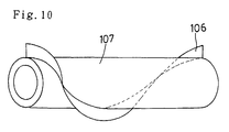
- Figure 10 is an oblique view of the blade of the third embodiment of the present invention.
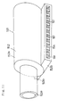
- Figure 11 is an oblique view of the electrostatic powder coating gun of the fourth embodiment of the present invention.
- Figure 12 is a transverse cross-sectional view of the electrostatic powder coating gun of the fourth embodiment of the present invention.
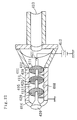
- Figure 13 is a longitudinal cross-sectional view of the electrostatic powder coating gun of the fourth embodiment of the present invention.
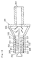
- Figure 14 is a longitudinal cross-sectional view of the electrostatic powder coating gun of the fifth embodiment of the present invention.
- Figure 15 is an oblique view of the electrostatic powder coating gun of the sixth embodiment of the present invention.
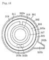
- Figure 16 is a transverse cross-sectional view of the electrostatic powder coating gun of the sixth embodiment of the present invention.
- Figure 17 is an oblique view of the blade of the sixth embodiment of the present invention.
- Figure 18 is an oblique view of the meshed element of the sixth embodiment of the present invention.
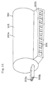
- Figure 19 is an oblique view of the electrostatic powder coating gun of the seventh embodiment of the present invention.
- Figure 20 is a transverse cross-sectional view of the electrostatic powder coating gun of the seventh embodiment of the present invention.
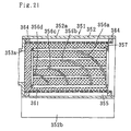
- Figure 21 is a longitudinal cross-sectional view of the electrostatic powder coating gun of the seventh embodiment of the present invention.
- Figure 22 is a longitudinal cross-sectional view of the electrostatic powder coating gun of the eighth embodiment of the present invention.
- Figure 23 is a longitudinal cross-sectional view of the electrostatic powder coating gun of the ninth embodiment of the present invention.
- Figure 24 is an oblique view of the linear elements of a modification of the present invention.
- the electrostatic powder coating gun 1 illustrated in Figure 1 has a cylindrical body 2 having a paint inlet 3 and a paint outlet 4. Powder paint transported by pressurized air is introduced from the inlet 3 into the body 2. The powder paint charged in the body 2 is blown out together with the pressurized air from the outlet 4. The powder paint is blown to the subject of coating to form a coating film.
- the body 2 is preferably formed from an insulating material or coated with an insulating material such as rubber.
- the inside of the body 2 constitutes a transportation path 5 for the powder paint.
- the transportation path 5 is surrounded by a cylindrical face 8 between the inlet and the outlet.
- the cylindrical face 8 is configured with the inner circumference of a cylindrical element 9 bonded to the inner circumference of the body 2.
- a plurality of first linear elements 11 are cantilevered so that the elements 11 are flexible.
- the plurality of first linear elements 11 extend toward the transportation path 5 like a brush.
- Each first linear element 11 arranged in the transportation path 5 is capable of coming in contact with the powder paint on transportation.
- Each first linear element 11 is extended along the radial direction of the cylindrical face 8. Also, each first linear element 11 is arranged along a spiral around the transporting direction of the powder paint.
- the cylindrical element 9 is made of a flexible square plate-like material illustrated in Figure 3 (1), which is cylindrically curved as illustrated in Figure 3 (2).
- the square plate-like material is, for example, flexible rubber.
- Each first linear element 11 is attached to the cylindrical element 9 before curving the plate-like material.
- second linear elements 22 described below are provided, the length of each first linear element 11 is shorter than the radius of the transportation path 5 surrounded by the cylindrical face 8.
- a support element 21 passing the central axis of the cylindrical face 8 in the transportation path 5 is attached to the body 2.
- a plurality of second linear elements 22 are cantilevered so that the elements 22 are flexible.
- Each second linear element 22 extends toward the transportation path 5.
- each second linear element 22 arranged in the transportation path 5 is capable of coming in contact with the powder paint on transportation.
- the direction of extension of each second linear element 22 is the radial direction of the cylindrical face 8.
- Each second linear element 22 is arranged along a spiral around the transporting direction of the powder paint.
- Each second linear element 22 and each first linear elements 11 are arranged so that they do not interfere with each other.
- each second linear element 22 is shorter than the radius of the cylindrical face 8.
- the length of each first linear element 11 is longer than the distance between each tip of the second linear element 22 and the cylindrical face 8.
- each of the linear elements 11 and 22 is electroconductive substance, such as an organic high molecular compound or a metal, which enables the powder paint to be charged by static electricity generated by friction between the powder paint and the elements 11, 22.
- the radius and number of the linear elements 11 and 22 are set so as to ensure a sufficient powder paint blowing capacity.
- the electrostatic powder coating gun 51 illustrated in Figure 5 has a cylindrical body 52. Powder paint transported by pressurized air is introduced from a paint inlet 53 into the body 52. The powder paint is blown out from a paint outlet 54 together with the pressurized air after being charged in the body 52. The powder paint is blown to the subject of coating.
- the body 52 is preferably formed from an insulating material or coated with an insulating material such as rubber.
- the inside of the body 52 constitutes a transportation path for the powder paint comprising a plurality of portions 55a, 55b, 55c and 55d.
- the transportation path portions 55a, 55b, 55c and 55d are surrounded by a plurality of mutually concentric cylindrical faces 58a, 58b, 58c and 58d between the inlet and the outlet.
- the cylindrical faces 58a, 58b, 58c and 58d are configured with the inner circumferences of cylindrical elements 59a, 59b, 59c and 59d bonded to the inner circumferences of cylindrical retention elements 68a, 68b, 68c and 68d.
- the retention elements 68a, 68b, 68c and 68d are mutually joined by joint elements 60a and 60b attached to the front and rear ends thereof, as illustrated in Figure 5.
- the joint elements 60a and 60b are fixed to the body 52.
- a plurality of linear elements 61 are cantilevered on each of the cylindrical faces 58a, 58b, 58c and 58d so that the elements 61 are flexible.
- the linear elements 61 extend toward the transportation path portions 55a, 55b, 55c and 55d like a brush.
- each linear element 61 arranged in the transportation path 5 is capable of coming in contact with the powder paint on transportation.
- Each linear element 61 extends along the radial direction of each of the cylindrical faces 58a, 58b, 58c and 58d, and is distributed over the entire region of each of the cylindrical faces 58a, 58b, 58c and 58d.
- a plurality of linear elements can be cantilevered by the cylindrical face on the outer circumference of the cylindrical element bonded to the outer circumference of each of the retention elements 68a, 68b, 68c and 68d so that the linear elements are flexible.
- Each of the cylindrical elements 59a, 59b, 59c and 59d is made of a flexible square plate-like material, which is cylindrically curved.
- Each linear element 61 is attached to each of the cylindrical elements 59a, 59b, 59c and 59d before curving the plate-like material.
- the material of each of the cylindrical elements 59a, 59b, 59c and 59d is electroconductive substance, such as rubber containing electroconductive particles.
- the length of each linear element 61 is roughly equal to the radial dimension of each of the transportation path portion 55a, 55b, 55c and 55d.
- a power source 62 for charging each linear element 61 is provided.
- the power source 62 is connected to one joint element 60a at one electrode and earthed at the other electrode.
- the material of the joint element 60a, retention elements 68a, 68b, 68c and 68d, cylindrical elements 59a, 59b, 59c and 59d, and linear elements 61 is electroconductive substance. By this arrangement, frictional charging of the powder paint as described below is promoted by the charge applied to each linear element 61.
- the insulating portion of the body 52 is preferably earthed.
- each of the linear elements 61 is electroconductive substance, such as a metal or an organic high molecular compound containing electroconductive particles, which enables the powder paint to be charged by static electricity generated by friction between the powder paint and the elements 61.
- the radius and number of the linear elements 61 are set so as to ensure a sufficient powder paint blowing capacity.
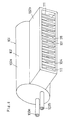
- a third embodiment of the present invention is hereinafter described with reference to Figures 8 through 10.
- the body 102 of the electrostatic powder coating gun 101 illustrated in Figure 8 has a cylindrical portion 102a and a rectangular parallelopipedic portion 102b extending from the outer circumference of the cylindrical portion 102a. On one end face of the cylindrical portion 102a, a paint inlet 103a and an auxiliary air inlet 103b are formed. On the rectangular parallelopipedic portion 102b, a paint outlet 104 is formed. Powder paint transported by pressurized air is introduced from the paint inlet 103a into the body 102. Pressurized air is introduced into the body 102 from the auxiliary air inlet 103b. The powder paint charged in the body 102 is blown out together with the pressurized air from the outlet 104. The powder paint is blown to the subject of coating to form a coating film.
- the body 102 is preferably formed from an insulating material or coated with an insulating material such as rubber.
- the inside of the body 102 constitutes a transportation path 105 for the powder paint.
- the transportation path 105 has a transporting direction changing portion 105a in the cylindrical portion 102a and a charging portion 105b in the rectangular parallelopipedic portion 102b positioned in the downstream side of the changing portion 105a.
- the changing portion 105a is provided with a blade 106 illustrated in Figure 10.
- the blade 106 is formed on an outer circumference of a cylindrical blade retention element 107.
- the blade retention element 107 is supported by the body 102 via a support ring 113 in the changing portion 105a so as to be rotatable.
- the rotation axis of the blade retention element 107 is arranged along the transporting direction before the change, i.e., the axial direction of the cylindrical portion 102a. By this arrangement, the blade 106 is arranged along a spiral around the transporting direction before the change.
- the paint inlet 103a and auxiliary air inlet 103b are arranged so that the powder paint and pressurized air introduced in the body 102 are guided to the blade 106.
- the blade 106 is rotated by the pressure of the air for transporting the powder paint.
- the transporting direction of the powder paint introduced in the body 102 is changed from the axial direction to the radial direction of the cylindrical portion 102a.
- the powder paint reaches the charging portion 105b.
- the powder paint is uniformly dispersed in the transportation path 105.
- Plate-like elements 117 are bonded to the upper and lower portions of the inside face of the rectangular parallelopipedic portion 102b.
- a plurality of linear elements 111 are cantilevered by the two plate-like elements 117 so that the elements 111 are flexible.
- These linear elements 111 extend toward the charging portion 105b in the transportation path 105 like a brush.
- each linear element 111 arranged in the transportation path 105 is capable of coming in contact with the powder paint on transportation.
- the direction of extension of each linear element 111 is vertical.
- the length of each linear element 111 is slightly shorter than the vertical dimension of the charging portion 105b.
- each of the linear elements 111 is electroconductive substance, such as an organic high molecular compound or a metal, which enables the powder paint to be charged by static electricity generated by friction between the powder paint and the elements 111.
- the radius and number of the linear elements 111 are set so as to ensure a sufficient powder paint blowing capacity.
- the body 152 of the electrostatic powder coating gun 151 illustrated in Figure 11 has a cylindrical portion 152a and a rectangular parallelopipedic portion 152b extending from the outer circumference of the cylindrical portion 152a.
- the cylindrical portion 152a has a paint inlet 153a on one end face and an auxiliary air inlet 153b on the outer circumference.
- a paint outlet 154 is formed on the rectangular parallelopipedic portion 152b.
- Powder paint transported by pressurized air is introduced from the paint inlet 153a into the body 152.
- Pressurized air is introduced from the auxiliary air inlet 153b into the body 152.
- the powder paint charged in the body 152 is blown out together with the pressurized air from the outlet 154.
- the powder paint is blown to the subject of coating to form a coating film.
- the body 152 is preferably formed from an insulating material or coated with an insulating material such as rubber.
- the inside of the body 152 constitutes a transportation path 155 for the powder paint.
- the transportation path 155 has a transporting direction changing portion 155a within the cylindrical portion 152a and a charging portion 155b within the rectangular parallelopipedic portion 152b positioned in the downstream side of the changing portion 155a.
- the changing portion 155a is provided with a plurality of blades 156a, 156b, 156c and 156d as illustrated in Figure 13.
- each of the blades 156a, 156b, 156c and 156d is fixed to the inner circumference of a frame-like blade retention element 157, which is fixed to one inner end face of the cylindrical portion 152a.
- the blades 156a, 156b, 156c and 156d are arranged along the transporting direction before the change, i.e., the axial direction of the cylindrical portion 152a.
- the blades 156a, 156b, 156c and 156d are arranged so that the surface area of the blade positioned in the downstream side is greater than that positioned in the upstream side.
- the transporting direction of the powder paint introduced from the paint inlet 153a into the changing portion 155a is changed from the axial direction of the cylindrical portion 152a to the direction toward the charging portion 155b, by the blades 156a, 156b, 156c and 156d.
- the air introduced from the auxiliary air inlet 153b into the body 152 promotes the introduction of the powder paint into the charging portion 155b. Because the surface area of the blade positioned in the downstream side is greater than that positioned in the upstream side, the powder paint is uniformly dispersed in the transportation path 155.
- Plate-like elements 167 are bonded to the upper and lower portions of the inside face of the rectangular parallelopipedic portion 152b of the body 152.
- a plurality of linear elements 161 are cantilevered by the two plate-like elements 167 so that the elements 167 are flexible.
- These linear elements 161 extend toward the charging portion 155b in the transportation path 155 like a brush.
- each linear element 161 arranged in the transportation path 155 is capable of coming in contact with the powder paint on transportation.
- the direction of extension of each linear element 161 is vertical.
- the length of each linear element 161 is slightly shorter than the vertical dimension of the charging portion 155b.
- each of the linear elements 161 is electroconductive substance, such as a metal or an organic high molecular compound containing electroconductive particles, which enables the powder paint to be charged by static electricity generated by friction between the powder paint and the elements 161.
- the radius and number of the linear elements 161 are set so as to ensure a sufficient powder paint blowing capacity.
- the electrostatic powder coating gun 201 illustrated in Figure 14 has a cylindrical body 202. Powder paint transported by pressurized air is introduced from an inlet 203 into the body 202. After being charged in the body 202, the powder paint is blown out from an outlet 204 together with the pressurized air. The powder paint is blown to the subject of coating to form a coating film.
- the body 202 is preferably formed from an insulating material or coated with an insulating material such as rubber.
- the inside of the body 202 constitutes a transportation path 205 of the powder paint.
- Dispersion blades 206 for dispersing the powder paint is attached to the inner face of the inlet side of the transportation path 205.
- the outlet side of the transportation path 205 is surrounded by a cylindrical face 208.
- the cylindrical face 208 is configured with the inner circumference of a cylindrical element 209 bonded to the inner circumference of the body 202.
- first linear elements 211 are cantilevered so that the elements 211 are flexible.
- the first linear elements 211 extend toward the transportation path 205 like a brush.
- each first linear element 211 arranged in the transportation path 205 is capable of coming in contact with the powder paint on transportation.
- the direction of extension of the first linear elements 211 is the radial direction of the cylindrical face 208.
- the cylindrical element 209 is made of a flexible square plate-like material such as rubber, which is cylindrically curved.
- Each first linear element 211 is attached to the cylindrical element 209 before curving the plate-like material.
- the length of each first linear element 211 is shorter than the radius of the transportation path 205 surrounded by the cylindrical face 208 because second linear elements 222 described below are provided.
- a support element 221 passing the central axis of the cylindrical face 208 in the transportation path 205 is attached to the body 202.
- a plurality of second linear elements 222 are cantilevered so that the elements 222 are flexible.
- These second linear elements 222 extend toward the transportation path 205, whereby each second linear element 222 arranged in the transportation path 205 is capable of coming in contact with the powder paint on transportation.
- Each second linear element 222 extends along the radial direction of the cylindrical face 208.
- the second linear elements 222 and the first linear elements 211 are arranged so that they do not interfere with each other.
- the length of each second linear element 222 is shorter than the radius of the cylindrical face 208.
- each first linear element 211 is longer than the distance between each tip of the second linear element 222 and the cylindrical face 208.
- the powder paint passing between the second linear elements 222 and the cylindrical face 208 is capable of coming in contact with the first linear elements 211.
- the tip of each first linear element 211 can be brought into contact with the support element 221 and the tip of each second linear element 222 can be brought into contact with the cylindrical face 208.
- a diffusion element 226 for the powder paint is attached to the tip of the support element 221.
- the second linear elements 222 are also attached to the diffusion element 226.
- each of the linear elements 211 and 222 is an electroconductive substance, such as an organic high molecular compound or a metal, which enables the powder paint to be charged by static electricity generated by friction between the powder paint and the elements 211, 212.
- the radius and number of the linear elements 211 and 222 are set so as to ensure a sufficient powder paint blowing capacity.
- the body 302 of the electrostatic powder coating gun 301 illustrated in Figure 15 has a cylindrical portion 302a and a prismatic portion 302b extending from the outer circumference of the cylindrical portion 302a.
- a paint inlet 303a and an auxiliary air inlet 303b are formed on one end face of the cylindrical portion 302a.
- a paint outlet 304 is formed on the prismatic portion 302b.
- Powder paint transported by pressurized air is introduced from the paint inlet 303a into the body 302.
- Pressurized air is introduced from the auxiliary air inlet 303b into the body 302.
- the powder paint charged in the body 302 is blown out together with the pressurized air from the outlet 304.
- the powder paint is blown to the subject of coating to form a coating film.
- the body 302 is preferably formed from an insulating material or coated with an insulating material such as rubber.
- the inside of the body 302 constitutes a powder paint transportation path 305.
- the transportation path 305 has a transporting direction changing portion 305a within the cylindrical portion 302a and an exit portion 305b within the prismatic portion 302b positioned in the downstream side of the changing portion 305a.
- the changing portion 305a is provided with a blade 306.
- the blade 306 is arranged along a spiral on the outer circumference of a cylindrical blade retention element 307.
- the blade retention element 307 is supported by the body 302 via a support ring 313 in the changing portion 305a so as to be rotatable.
- the rotation axis of the blade retention element 307 is arranged along the transporting direction before the change, i.e., the axial direction of the cylindrical portion 302a. By this arrangement, the blade 306 is arranged along a spiral around the transporting direction before the change.
- the paint inlet 303a and auxiliary air inlet 303b are arranged so that the powder paint and pressurized air introduced in the body 302 reach the blade 306.
- the blade 306 is rotated by the pressure of the air for transporting the powder paint.
- the transporting direction of the powder paint introduced in the body 302 is changed from the axial direction to the radial direction of the cylindrical portion 302a.
- the powder paint reaches the exit portion 305b.
- the powder paint is uniformly dispersed in the transportation path 305.
- the transportation path 305 is provided with a cylindrical meshed element 311 as illustrated in Figure 18.
- the meshed element 311 is arranged along a cylindrical face surrounding the blade 306.
- the mesh size of the meshed element 311 is greater than the size of the particles constituting the powder paint.
- the meshed element 311 is capable of coming in contact with the powder paint on transportation, after the change of the transporting direction of the powder paint.
- the meshed element 311 is supported by the body 302 via a support ring 314 in the changing portion 305a so as to be rotatable.
- the rotation axis of the meshed element 311 is arranged along the transporting direction before the change, i.e., the axial direction of the cylindrical portion 302a. By this arrangement, the meshed element 311 is rotated by the pressure of the air for transporting the powder paint.
- the material of the meshed element 311 is an electroconductive substance, such as an organic high molecular compound or a metal, which enables the powder paint to be charged by static electricity generated by friction between the powder paint and the element 311. By this arrangement, the charged powder paint is blown out from the outlet 304 via the exit portion 305b.
- the dimensions of the meshed element 311 are set so as to ensure a sufficient powder paint blowing capacity.
- a seventh embodiment of the present invention is hereinafter described with reference to Figures 19 through 21.
- the body 352 of the electrostatic powder coating gun 351 as illustrated in Figure 19 has a cylindrical portion 352a and a prismatic portion 352b extending from the outer circumference of the cylindrical portion 352a.
- the cylindrical portion 352a has a paint inlet 353a on one end face and an auxiliary air inlet 353b in the outer circumference.
- a paint outlet 354 is formed on the prismatic portion 352b.
- Powder paint transported by pressurized air is introduced from the paint inlet 353a into the body 352.
- Pressurized air is introduced from the auxiliary air inlet 353b into the body 352.
- the powder paint charged in the body 352 is blown out together with the pressurized air from the outlet 354.
- the powder paint is blown to the subject of coating to form a coating film.
- the body 352 is preferably formed from an insulating material or coated with an insulating material such as rubber.
- the inside of the body 352 constitutes a powder paint transportation path 355.
- This transportation path 355 has a transporting direction changing portion 355a within the cylindrical portion 352a and an exit portion 355b within the prismatic portion 352b positioned in the downstream side of the changing portion 355a.
- the changing portion 355a is provided with a plurality of blades 356a, 356b, 356c and 356d.
- each of the blades 356a, 356b, 356c and 356d is fixed to the inner circumference of a frame-like blade retention element 357, which is fixed to the inner end surface of the cylindrical portion 352a.
- the blades 356a, 356b, 356c and 356d are arranged along the transporting direction before the change, i.e., the axial direction of the cylindrical portion 352a.
- the surface area of the blade positioned in the downstream side is greater than that positioned in the upstream side.
- the transporting direction of the powder paint introduced from the paint inlet 353a into the changing portion 355a is changed from the axial direction of the cylindrical portion 352a to the direction toward the exit portion 355b by the blades 356a, 356b, 356c and 356d.
- the air introduced from the auxiliary air inlet 353b into the body 352 promotes the introduction of the powder paint into the exit portion 355b. Because the surface area of the blade positioned in the downstream side is greater than that positioned in the upstream side, the powder paint is uniformly dispersed in the transportation path 355.
- the transportation path 355 is provided with a cylindrical meshed element 361 arranged along a cylindrical face surrounding the blades 356a, 356b, 356c and 356d.
- the mesh size of the meshed element 361 is greater than the size of the particles constituting the powder paint.
- the meshed element 361 is capable of coming in contact with the powder paint on transportation, after the change of the transporting direction.
- the meshed element 361 is supported concentrically with the center of the transporting direction before the change, i.e., the axial direction of the cylindrical portion 352a, by the body 352 via a support ring 364 in the changing portion 355a.
- a power source 362 for charging the meshed element 361 is provided.
- the power source 362 is connected to the meshed element 361 at one electrode and earthed at the other electrode.
- the material of the meshed element 361 is electroconductive substance. By this arrangement, frictional charging of the powder paint as described below is promoted by the charge applied to the meshed element 361.
- the insulating portion of the body 352 is preferably earthed.
- the material of the meshed element 361 is electroconductive substance, such as a metal or an organic high molecular compound containing electroconductive particles, which enables the powder paint to be charged by static electricity generated by friction between the powder paint and the element 361. By this arrangement, the charged powder paint is blown out from the outlet 354 via the exit portion 355b.
- the dimensions of the meshed element 361 are set so as to ensure a sufficient powder paint blowing capacity.
- the electrostatic powder coating gun 401 illustrated in Figure 22 has a cylindrical body 402. Powder paint transported by pressurized air is introduced from an inlet 403 into the body 402. After being charged in the body 402, the powder paint is blown out from an outlet 404 together with the pressurized air. The powder paint is blown to the subject of coating to form a coating film.
- the body 402 is preferably formed from an insulating material or coated with an insulating material such as rubber.
- the inside of the body 402 constitutes a powder paint transportation path 405.
- the inlet side of the transportation path 405 is surrounded by a conical face that tapers toward the outlet side.
- the outlet side of the transportation path 405 is surrounded by a cylindrical face 408.
- each support element 420 By the cylindrical face 408 on the inner circumference of the transportation path 405, a plurality of ring-shaped support elements 420 are supported in an array along the direction of the powder paint transporting direction. By the inner circumference of each support element 420, a meshed element 411 is retained. The mesh size of the meshed element 411 is greater than the size of the particles constituting the powder paint. By this arrangement, each meshed element 411 arranged in the transportation path 405 is capable of coming in contact with the powder paint on transportation.
- a shaft 421 penetrating each meshed element 411 is attached to the body 402.
- a powder paint diffusion element 426 is attached to the tip of the shaft 421.
- a power source 412 for charging the meshed element 411 is provided.
- the power source 412 is connected to one end of the shaft 421 at one electrode and earthed at the other electrode.
- the material of the meshed element 411, the shaft 421 and the support element 420 is electroconductive substance. By this arrangement, frictional charging of the powder paint as described below is promoted by the charge applied to each meshed element 411.
- the insulating portion of the body 402 is preferably earthed.
- each of the meshed element 411 is electroconductive substance, such as a metal or an organic high molecular compound containing electroconductive particles, which enables the powder paint to be charged by static electricity generated by friction between the powder paint and the element 411. By this arrangement, the charged powder paint is blown out from the outlet 404.
- the dimensions and number of the meshed elements 411 are set so as to ensure a sufficient powder paint blowing capacity.
- the electrostatic powder coating gun 451 of a ninth embodiment of the present invention is hereinafter described with reference to Figure 23. Differences from the eighth embodiment are described, and common portions to this embodiment and the eighth embodiment are indicated by the same symbols.
- each linear element 461 is supported at both ends by the inner circumference of each support element 420.
- the longitudinal direction of each linear element 461 is parallel to the radial direction of the cylindrical face 408.
- the longitudinal directions of the plurality of linear elements 461 supported by the same support element 420 are parallel to each other.
- the longitudinal directions of the linear elements 461 supported by each support element 420 are not parallel to the longitudinal directions of the linear elements 461 supported by the adjoining support element 420.
- the interval of the plurality of linear elements 461 in each support element 420 is greater than the size of the particles constituting the powder paint.
- a power source 412 for charging each linear element 461 is provided.
- the power source 412 is connected to one end of the shaft 421 at one electrode and earthed at the other electrode.
- the material of the linear element 461, the support element 420 and the shaft 421 is electroconductive substance. By this arrangement, frictional charging of the powder paint as described below is promoted by the charge applied to each linear element 461.
- the insulating portion of the body 402 is preferably earthed.
- each of the linear element 461 is electroconductive substance, such as a metal or an organic high molecular compound containing electroconductive particles, which enables the powder paint to be charged by static electricity generated by friction between the powder paint and the element 461. By this arrangement, the charged powder paint is blown out from the outlet 404.
- the radius and number of the linear elements 461 are set so as to ensure a sufficient powder paint blowing capacity.
- the other aspects are the same as those in the eighth embodiment.
- the electrostatic powder coating guns 1, 51, 101, 151, 201, 301, 351, 401 and 451 of the above-described embodiments charge powder paint by static electricity generated by friction, ozone odor is not generated, the entry of powder paint into the hollows of the subject of coating is good, and craters and pinholes are unlikely to occur in the coating film. This facilitates the obtainment of a smooth uniform coating film with minimum dust adhesion.
- the static electricity can be generated by contacting the linear elements 11, 22, 61, 111, 161, 211 and 222 with the particles of the powder paint in the transportation paths 5, 55, 105, 155 and 205, by contacting the meshed elements 311, 361 and 411 with the particles of the powder paint in the transportation paths 305, 355 and 405, or by contacting the linear element 461 with the particles of the powder paint in the transportation path 405.
- the chance of contact between the linear elements 11, 22, 61, 111, 161, 211 and 222 and the particles increases in proportion to the number of linear elements 11, 22, 61, 111, 161, 211 and 222.
- the chance of contact between the meshed elements 311, 361 and 411 and the particles increases in proportion to the number of opens of the meshed elements 311, 361 and 411.
- the chance of contact between the linear element 461 and the particles increases in proportion to the number of the linear elements 461.
- the charge efficiency of the particle can be improved significantly.
- the maximum blowing capacity and coating efficiency of the powder paint is increased, so that quick coating is possible even when the subject of coating has a wide surface area. Because the linear elements 11, 22, 61, 111, 161, 211 and 222 are flexible by contact with the powder paint, the wear due to the contact is mitigated, resulting in extended life.
- the powder paint can be stably charged. Also, because structural simplicity reduces cost and facilitates maintenance and cleaning, the use of powder paint of different colors is facilitated.
- each of the linear elements 11, 22, 211 and 222 extends from the cylindrical faces 8 and 208 and the support elements 21 and 221, which passes the central axes of the cylindrical faces 8 and 208, toward the transportation paths 5 and 205 surrounded by the cylindrical faces 8 and 208. Because the chance of contact between each of the linear elements 11, 22, 211 and 222 and the particles can be thus uniformized, the charge efficiency can be uniformly improved to obtain a uniform coating film.
- the linear elements 11 and 22 are arranged along a spiral around the transporting direction of the powder paint.
- the powder paint can be thus rotated, so that the chance of contact between the linear elements 11 and 22 and the powder paint is increased.
- the charge efficiency for the powder paint can be further improved.
- the linear elements 61 extend from the cylindrical faces 58a, 58b, 58c and 58d to the transportation path portions 55a, 55b, 55c and 55d surrounded by a plurality of cylindrical faces 58a, 58b, 58c and 58d.
- the chance of contact between the linear elements 61 and the powder paint can be increased to improve the charge efficiency.
- the powder paint can be uniformly charged by uniformly dispersing it to obtain a uniform coating film. Furthermore, by applying a charge to each linear element 61, powder paint charge efficiency can be further improved.
- the chance of contact between the linear elements 111 and 161 and the powder paint can be increased to improve charge efficiency by dispersing the powder paint by the blades 106, 156a, 156b, 156c and 156d.
- the powder paint can be uniformly charged by uniformly dispersing it when the transporting direction of the powder paint is changed by the blades 106, 156a, 156b, 156c and 156d.
- the powder paint can be uniformly charged, because it is dispersed by the dispersion blade 206 before being brought into contact with the linear elements 211 and 222.
- the chance of contact between the meshed elements 311 and 361 and the powder paint can be increased to improve the charge efficiency by dispersing the powder paint by the blades 306, 356a, 356b, 356c and 356d.
- the powder paint can be uniformly charged by uniformly dispersing it by the blades 306, 356a, 356b, 356c and 356d before being brought into contact with the meshed elements 311 and 361.
- the meshed elements 311 and 361 are arranged along a cylindrical face surrounding the blades 306, 356a, 356b, 356c and 356d, the chance of contact with the powder paint is significantly increased to improve the charge efficiency.
- the meshed element 311 can contact with the powder paint without localizing the contact point to prevent the meshed element 311 from clogging, because the meshed element 311 arranged along the cylindrical face rotates.
- the powder paint charge efficiency can be further improved by applying a charge to the meshed elements 361 and 411 or the linear element 461.
- the above-described electrostatic powder coating guns 1, 51, 101, 151, 201, 301, 351, 401 and 451 are capable of uniformly improving the powder paint charge efficiency, they are suited for blowing powder paint of a single uniform hue, which is obtained by mixing different powder paints of two or more hues, for color coating.
- the loose apparent density difference between the powder paints to be mixed is preferably within 0.02 g/cc.
- the charge amount difference between the powder paints to be mixed is preferably within 5 ⁇ C/g, the dielectric constant difference is preferably within 0.2, and the resistance ratio is preferably between 1/10 and 10.
- the softening point difference between the powder paints to be mixed is within 5°C, that the melt viscosity difference at 120°C is within 300 cp, more preferably within 100 cp, and that the setting time difference is within 2 minutes, more preferably within 1 minute.
- the present invention is not limited to the above-described embodiments.
- An electrostatic powder coating gun combining characteristics of the above-described embodiments can be constituted.
- the setting and arrangement of the linear elements are not subject to limitation.
- the cylindrical meshed elements 311 and 361 can be replaced with a plurality of mutually parallel linear elements 461' supported at both ends by a ring-shaped support element 420', as illustrated in Figure 24. In this case, the interval of the linear elements 461' is greater than the size of powder particles.
- the arrangement of the meshed elements is not subject to limitation; for example, the cylindrical meshed elements 311 and 361 in the sixth and seventh embodiments can be replaced with plate-like meshed elements arranged in the exit portions 305b and 355b.
- the materials of the linear elements and meshed elements are not subject to limitation, as long as they are capable of charging the powder paint by static electricity generated by friction between the powder paint and the elements.
Landscapes
- Electrostatic Spraying Apparatus (AREA)
Applications Claiming Priority (4)
| Application Number | Priority Date | Filing Date | Title |
|---|---|---|---|
| JP13091296A JPH09290182A (ja) | 1996-04-25 | 1996-04-25 | 静電粉体塗装用ガン |
| JP130900/96 | 1996-04-25 | ||
| JP130912/96 | 1996-04-25 | ||
| JP13090096A JPH09290180A (ja) | 1996-04-25 | 1996-04-25 | 静電粉体塗装用ガン |
Publications (2)
| Publication Number | Publication Date |
|---|---|
| EP0808664A2 true EP0808664A2 (de) | 1997-11-26 |
| EP0808664A3 EP0808664A3 (de) | 1998-11-25 |
Family
ID=26465893
Family Applications (1)
| Application Number | Title | Priority Date | Filing Date |
|---|---|---|---|
| EP97106822A Withdrawn EP0808664A3 (de) | 1996-04-25 | 1997-04-24 | Elektrostatische Pulver-Beschichtungspistole |
Country Status (3)
| Country | Link |
|---|---|
| US (1) | US5894989A (de) |
| EP (1) | EP0808664A3 (de) |
| TW (1) | TW340063B (de) |
Families Citing this family (6)
| Publication number | Priority date | Publication date | Assignee | Title |
|---|---|---|---|---|
| US7165732B2 (en) | 2004-01-16 | 2007-01-23 | Illinois Tool Works Inc. | Adapter assembly for a fluid supply assembly |
| US7665672B2 (en) | 2004-01-16 | 2010-02-23 | Illinois Tool Works Inc. | Antistatic paint cup |
| US7086549B2 (en) | 2004-01-16 | 2006-08-08 | Illinois Tool Works Inc. | Fluid supply assembly |
| US7766250B2 (en) | 2004-06-01 | 2010-08-03 | Illinois Tool Works Inc. | Antistatic paint cup |
| US7757972B2 (en) | 2004-06-03 | 2010-07-20 | Illinois Tool Works Inc. | Conversion adapter for a fluid supply assembly |
| US7353964B2 (en) | 2004-06-10 | 2008-04-08 | Illinois Tool Works Inc. | Fluid supply assembly |
Family Cites Families (14)
| Publication number | Priority date | Publication date | Assignee | Title |
|---|---|---|---|---|
| US2657339A (en) * | 1953-10-27 | Method and apparatus for producing | ||
| US913941A (en) * | 1908-11-17 | 1909-03-02 | Lucien I Blake | Ionizer or apparatus for producing gaseous ions. |
| FR55166E (fr) * | 1946-10-21 | 1951-10-02 | Perfectionnements aux méthodes de poudrage utilisées en agriculture | |
| US3696152A (en) * | 1970-06-17 | 1972-10-03 | Dow Chemical Co | Hydration of nitriles to amides using heterogeneous cupreous catalysts |
| GB1351944A (en) * | 1970-07-15 | 1974-05-15 | Nat Res Dev | Electrostatic deposition of particles |
| GB1387632A (en) * | 1971-04-08 | 1975-03-19 | Mitchell J R | Apparatus for electrically charging and ejecting particles of material |
| CH622444A5 (de) * | 1977-04-04 | 1981-04-15 | Gruenenfelder H Eltex Elektron | |
| DE2938806A1 (de) * | 1978-09-26 | 1980-04-03 | Toyota Motor Co Ltd | Triboelektrische pulverspruehpistole |
| NL187729C (nl) * | 1980-01-04 | 1992-01-02 | Icab Ind Coating Ab | Elektrostatische poederspuit. |
| SU912296A1 (ru) * | 1980-07-02 | 1982-03-15 | Предприятие П/Я А-3826 | Диффузор дл распылени волокнистого материала |
| SE446826B (sv) * | 1981-04-24 | 1986-10-13 | Icab Ind Coating Ab | Pulverspruta med elektrostatisk laddningsformaga bestaende av langstreckta krokta laddningskanaler vilka krokts att bilda loopar eller vagor anordnade i ett flertal grupper |
| US4886815A (en) * | 1984-06-20 | 1989-12-12 | Schachar Ronald A | Treatment and prevention of retinal edema with dopaminergic antagonists |
| JP3407337B2 (ja) * | 1993-06-14 | 2003-05-19 | 旭サナック株式会社 | 静電塗装用摩擦帯電ガン |
| JPH0724366A (ja) * | 1993-07-15 | 1995-01-27 | Nordson Kk | 静電粉体塗装用噴出ガン |
-
1997
- 1997-04-17 TW TW086104997A patent/TW340063B/zh active
- 1997-04-22 US US08/844,776 patent/US5894989A/en not_active Expired - Fee Related
- 1997-04-24 EP EP97106822A patent/EP0808664A3/de not_active Withdrawn
Also Published As
| Publication number | Publication date |
|---|---|
| EP0808664A3 (de) | 1998-11-25 |
| US5894989A (en) | 1999-04-20 |
| TW340063B (en) | 1998-09-11 |
Similar Documents
| Publication | Publication Date | Title |
|---|---|---|
| JP2005046842A (ja) | 被覆材料の帯電粒子を定量吐出する方法および装置 | |
| US3806763A (en) | Electrified particles generating apparatus | |
| FI91720C (fi) | Laite työkappaleiden sähköstaattiseen päällystämiseen | |
| JP3184455B2 (ja) | 回転霧化頭型塗装装置 | |
| JP3291503B2 (ja) | 静電噴霧装置 | |
| US20020043576A1 (en) | Rotary atomizer with bell element | |
| US5894989A (en) | Electrostatic powder coating gun | |
| KR100351782B1 (ko) | 회전무화헤드형 도장장치 | |
| US4158071A (en) | Method and apparatus for power coating of three-piece cans | |
| US7240861B2 (en) | Method and apparatus for dispensing paint powders for powder coatings | |
| JPS61283369A (ja) | 粉末状被膜材料を静電被膜する方法及び装置 | |
| JP2016516576A (ja) | 液体塗布製品を噴霧する静電噴霧装置、及びかかる噴霧装置を備える噴霧設備 | |
| KR0184124B1 (ko) | 다중대전 현상건 | |
| US4854500A (en) | Apparatus and method to produce charged fog | |
| US5788165A (en) | Rotary atomizing head of a rotary atomizing electrostatic coating apparatus | |
| Intra et al. | Evaluation of the performance in charging efficiencies and losses of ultrafine particles ranging in sizes from 15 to 75 nm in a unipolar corona-based ionizer | |
| CA2322256C (en) | High voltage source rotary spray | |
| EP0697255A2 (de) | Verfahren und Vorrichtung zur elektrostatischen Pulverbeschichtung | |
| JPH09290182A (ja) | 静電粉体塗装用ガン | |
| JPH09290181A (ja) | 静電粉体塗装用ガン | |
| JPH1057846A (ja) | 粉体塗料用静電塗装機 | |
| JP3817165B2 (ja) | 欠陥検査装置 | |
| US7520450B2 (en) | Electrical connections for coating material dispensing equipment | |
| Murata et al. | Enhancement of frictional charging characteristics of polymer powder by plasma treatment | |
| KR0184123B1 (ko) | 음극선관 패널의 현상장치 |
Legal Events
| Date | Code | Title | Description |
|---|---|---|---|
| PUAI | Public reference made under article 153(3) epc to a published international application that has entered the european phase |
Free format text: ORIGINAL CODE: 0009012 |
|
| AK | Designated contracting states |
Kind code of ref document: A2 Designated state(s): DE FR GB IT |
|
| PUAL | Search report despatched |
Free format text: ORIGINAL CODE: 0009013 |
|
| AK | Designated contracting states |
Kind code of ref document: A3 Designated state(s): DE FR GB IT |
|
| 17P | Request for examination filed |
Effective date: 19990428 |
|
| 17Q | First examination report despatched |
Effective date: 20010525 |
|
| STAA | Information on the status of an ep patent application or granted ep patent |
Free format text: STATUS: THE APPLICATION IS DEEMED TO BE WITHDRAWN |
|
| 18D | Application deemed to be withdrawn |
Effective date: 20011005 |