EP0808645B1 - Spielfahrzeug - Google Patents
Spielfahrzeug Download PDFInfo
- Publication number
- EP0808645B1 EP0808645B1 EP97303426A EP97303426A EP0808645B1 EP 0808645 B1 EP0808645 B1 EP 0808645B1 EP 97303426 A EP97303426 A EP 97303426A EP 97303426 A EP97303426 A EP 97303426A EP 0808645 B1 EP0808645 B1 EP 0808645B1
- Authority
- EP
- European Patent Office
- Prior art keywords
- vehicle
- cam
- lever
- wheel
- vehicle toy
- Prior art date
- Legal status (The legal status is an assumption and is not a legal conclusion. Google has not performed a legal analysis and makes no representation as to the accuracy of the status listed.)
- Expired - Lifetime
Links
Images


Classifications
-
- A—HUMAN NECESSITIES
- A63—SPORTS; GAMES; AMUSEMENTS
- A63H—TOYS, e.g. TOPS, DOLLS, HOOPS OR BUILDING BLOCKS
- A63H7/00—Toy figures led or propelled by the user
- A63H7/02—Toy figures led or propelled by the user by pushing or drawing
- A63H7/04—Toy figures led or propelled by the user by pushing or drawing moving together with a toy vehicle or together with wheels rolling on the ground, i.e. driven by vehicle or wheel movement
-
- A—HUMAN NECESSITIES
- A63—SPORTS; GAMES; AMUSEMENTS
- A63H—TOYS, e.g. TOPS, DOLLS, HOOPS OR BUILDING BLOCKS
- A63H5/00—Musical or noise- producing devices for additional toy effects other than acoustical
Definitions
- the present invention relates to a vehicle toy, for example, to a vehicle toy comprising a plurality of connected vehicles, which travels by pulling by the hand and in which a doll or the like on a vehicle plays a musical instrument such as a percussion instrument and the like in synchronization with the traveling thereof.
- a handcart toy generating a sound with traveling in which when a truck provided with a handle which is arranged at an upper position of the truck, is run by pushing the handle by the hand, a cam attached to a wheel axle of the truck is rotated to swing a plurality of levers on vertical planes, which are provided in a front side of the truck, so that the top end of each lever is struck against a corresponding portion struck of the truck to generate a sound, has been known up to this time.
- US-A-2 883 793 discloses an action toy having one or more movable members actuated by rolling the toy along a supporting surface to strike one or more of a number of musical sound producing means in a manner producing musical sounds varying as to pitch, tone or the like.
- An object of the present invention is to provide a vehicle toy which travels by pulling with the hand and the like and which has various types of play modes which can be selected at pleasure.
- a vehicle toy is provided, as claimed in Claim 1.
- a connecting member is required for each of the rear portion of the leading vehicle and the front portion of the following vehicle.
- a connecting member is required not only for each of the rear portion of the leading vehicle and the front portion of the rear vehicle but also for each of front and rear portions of the intermediate vehicles.
- the member struck by the striking member is a percussion instrument.
- the vehicle toy having such a structure, by pulling a vehicle by the hand through a string or the like, even a person who cannot walk stably enough, such as a little child can safely play. Further, it is possible not only to travel the vehicle but to play a musical instrument in synchronization with the traveling. Therefore, it is possible to make a little child or the like more pleased.
- a vehicle toy is provided, as claimed in Claim 3.
- the sound generating member is a bell and cymbals are attached to ends of the pair of arms.
- the bell is rung to generate a false sound of cymbals together with a swinging motion of the cymbal, it gives a little child or the like a little surprise and therefore makes them more happy.
- the cam preferably comprises a rotary disc supported by an axle of the wheel and a pin erected on the rotary disc at an eccentric position.
- a plurality of pin holes for tightly fitting a plurality of pins therein may be formed in the rotary disc at eccentric positions so that the pin holes permit installation and removal of the pins.
- the cam is connected to the wheel through a clutch so that a connection between the cam and the wheel is released through the clutch when the cam is overloaded.
- the clutch may comprise a clutch disc which is arranged next to a surface of the rotary disc fixed to a wheel axle and a spring for biasing the rotary disc to push against the clutch disc, and a plurality of projections are provided on one of the clutch and the rotary disc and a plurality of recess portions are formed in the other thereof so that these projections can fit into the recess portions.
- the vehicle toy comprises a plurality of vehicles which are connected to each other through the connecting member.
- Each of the vehicles may have a musical instrument different from each other, for example, a glockenspiel or a xylophone, a high drum, cymbals, and the like.
- a musical instrument different from each other, for example, a glockenspiel or a xylophone, a high drum, cymbals, and the like.
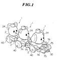
- FIG. 1 shows a vehicle toy which travels by pulling by the hand, which comprises three vehicles 1, 1 and 1 connected.
- a first vehicle leading vehicle for playing a glockenspiel (or a xylophone)
- a second vehicle intermediate vehicle for beating a high drum
- a third vehicle rear vehicle for playing cymbals
- FIG. 2 shows the second vehicle 1 for beating a high drum.
- the second vehicle 1 comprises a body 2 which is divided into a lower case 10 and an upper case 20, a head part 24, and a pair of wheels 40 and 40.
- a pair of notches 11 and 11 are formed in both side walls and a pair of ribs 12 and 12 are erected on the inner bottom surface.
- a notch 13 is formed in the upper end surface of each rib 12.
- a recess 14 is formed at a lower position and a stay 15 is tightly attached into the recess 14.
- a front wheel 16 is disposed on a lower portion of the top end of the stay 15 and a projection 31 for functioning as one of a connecting means 30 is formed on an upper portion of the top end thereof.
- a stay 17 is disposed at a lower position to extend backward and a recess 32 for functioning as the other of the connecting means 30 is formed in the lower surface of the top end of the stay 17.
- a projection 31 of a connecting means 30 in another vehicle 1 can be fitted.
- a through hole 18 for passing a string or the like therethrough is formed in the side walls of the top end of the stay 15.
- a pair of tongue pieces 21 and 21 are formed to extend downward on the lower ends of both side walls and a pair of notches 22 and 22 are formed in the lower ends of both side walls (only one side is shown in FIG. 2).
- a T-shaped projection 23 is erected on the upper surface of the upper case 20, a T-shaped projection 23 is erected.
- the projection 23 is for coupling the body 2 with the head part 24 having a figure of an animal or the like.
- the head part 24 comprises a front face portion 25 and a rear face portion 26 which have notches 25a and 26a formed in the bottom surfaces, respectively. These notches 25a and 26a form a hole when the front and rear face portions 25 and 26 are brought together so that the T-shaped projection 23 can be tightly fitted in the hole, and thus the head part 24 is attached to the body 2.
- the vehicle 1 is provided with a pair of wheels 40 and 40.
- Each a pair of wheels 40 and 40 comprises a wheel disc 41, a rubber belt 42 disposed on the periphery of the wheel disc 41, and a wheel cover 43 for covering the outer side surface of the wheel disc 41.
- Both wheels 40 and 40 are adhered to both ends of a wheel axle 44.
- the wheel axle 44 is arranged in the pair of notches 11 and 11 of the lower case 10, and thereafter when the upper case 20 is combined with the lower case 10 so as to tightly fit the top ends of the tongue pieces 21 of the upper case 20 into the notches 11 of the lower case 10, the movement of the wheel axle 44 is rotatably restricted within the notches 11 by the top ends of the tongue pieces 21.
- a cam 50 comprising a rotary disc 51 and a plurality of pins 52 erected on the rotary disc 51, is arranged.
- a plurality of pin holes 53 for selectively setting the operation timing and the amount of swing, of levers which will be explained later, are formed.
- the pins 52 are tightly fitted into the pin holes 53 appropriately so that the pin holes 53 permit installation and removal of the pins 52. It is possible to generate various types of original sounds by changing the positions to fit the pins 52 therein to change the operation timing or the amount of swing, of the levers.
- the rotary disc 51 is arranged so that it is capable of rotation to the wheel disc 41 and of slide in an axial direction.
- the cam 50 is connected to the wheel axle 44 and the wheel 40 through a clutch 60.
- the clutch 60 comprises a clutch disc 61 which is arranged to face to a surface of the rotary disc 51 and fixed to the wheel axle 44 in a side, a stopper 62 which is fixed to the wheel axle 44 in the other side, and a coil spring 63 which is arranged between the stopper 62 and the rotary disc 51.
- the rotary disc 51 is pressed against the clutch disc 61 by a biasing force due to the coil spring 63. Therefore, when the clutch disc 61 is rotated by rotation of the wheel axle 44, the rotary disc 51 is rotated by a friction force between the clutch disc 61 and the rotary disc 51.
- the clutch disc 61 slips on the rotary disc 51.
- a plurality of projections 54 are provided on the surface of the rotary disc 51 and a plurality of recess portions 64 are formed in the clutch disc 61 so that these projections 54 can fit into the recess portions 64, thereby it is possible to increase the friction force between the clutch disc 61 and the rotary disc 51.
- the projections 54 may be provided on the surface of the clutch disc 61 and the recess portions 64 may be formed in the rotary disc 51. According to the vehicle toy having such a structure, because the connection between the cam and the wheel is released through the clutch when the cam is overloaded, it is possible to prevent damage of the internal mechanism by an overload.
- a shaft 70 is fitted.
- the movement of the shaft 70 is rotatably restricted within the notches 13 by the top ends of the ribs.
- Both ends of the shaft 70 are fitted into holes formed in base portions of a pair of levers 71 and 71.
- Each lever 71 has an arm 73 through a connecting rod 72 as a body and has a stick (striking member) 74 at the top end thereof.
- a boss 19 is provided on the upper surface of the stay 15 supporting the front wheel 16. The boss 19 is tightly fitted into a through hole 75a which is formed in a portion of a high drum member (a member struck) 75.
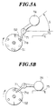
- Each lever 71 is arranged so that an end portion 71a is in the area in which it can be operated by the pins 52 of the cam 50, as shown in FIGS. 5A and 5B. Therefore, when the rotary disc 51 is rotated, the pin 52 pushes the end portion 71a of the lever 71 down, as shown in FIG. 5A. Consequently, the lever 71, the connecting rod 72, the arm 73 and the stick 74 which are constituted as a body are rotated around the shaft 70, and thereby the stick 74 is swung up. Thereafter, when the end portion 71a of the lever 71 is disengaged from the pin 52, the stick 74 falls down by its own weight and collides against the high drum 75 to generate a sound, as shown in FIG. 5B.
- the above-described embodiment can be used for a vehicle for playing a glockenspiel or a xylophone by substituting a glockenspiel or a xylophone for the high drum 75.
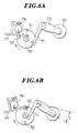
- FIGS. 6A and 6B An embodiment of a vehicle for playing cymbals is shown in FIGS. 6A and 6B.
- the vehicle differs from the above-explained vehicle for beating the high drum in that cymbals 76 are used in place of the stick 74 and a dummy sound generating device is added.
- the same reference numerals are attached to structural members, elements or the like corresponding to those of the vehicle for beating the high drum.
- a cymbal 76 is arranged to the top end of an arm 73 which is connected to each lever 71 as a body.
- a dummy sound generating device comprising a pair of sound generating members is swingably disposed to the lower case 10.
- Each sound generating member comprises a supplemental lever 77 which is swingable around an axis (which is positioned at the left end of the supplemental lever 77 in FIG. 6A) attached to the lower case 10, and a bell 78 which is hung on a supporting member mounted to the supplemental lever 77.
- a plurality of vehicles 1, 1 and 1 each having such a structure e.g., a first vehicle for playing a glockenspiel (or a xylophone), a second vehicle for beating a high drum, and a third vehicle for playing cymbals, are connected with one another through the connecting means 30, and thereafter a string or the like is tied to the front portion of the connecting means 30 through the hole 18 which is formed in the front portion of the lead vehicle 1.
- the vehicle toy comprising a plurality of vehicles 1, 1, and 1 is run by pulling the string or the like by the hand.
- the vehicle toy having a structure of the above embodiment by pulling a vehicle by the hand through a string or the like, even a person who cannot walk stably enough, such as a little child can safely play. Further, it is possible not only to travel the vehicle but to play a musical instrument in synchronization with the traveling. Therefore, it is possible to make a little child or the like more pleased. Further, according to the vehicle toy of the embodiment, because the number and the order of the vehicles having various types of musical instruments can be freely changed, it is possible to provide a large diversity of pleasure. Because the stroke of the lever can be changed by changing the positions to fit the pins and the number of sound generation can be increased by increasing the number of pins fitted, it is possible to provide a large diversity of pleasure.
Landscapes
- Physics & Mathematics (AREA)
- Engineering & Computer Science (AREA)
- Acoustics & Sound (AREA)
- Multimedia (AREA)
- Toys (AREA)
Claims (10)
- Spielzeugfahrzeug mit zumindest einem Fahrzeug (1), das durch Ziehen mit der Hand fortbewegt wird und synchron mit einer Fortbewegung desselben ein Musikinstrument spielt, wobei das Fahrzeug umfaßt: eine Puppe mit einer schwenkbaren Schlageinrichtung (74), einen Körper (2), der mit einem Verbindungsglied (30) versehen ist, welches dazu geeignet ist, das Fahrzeug mit einem anderen Fahrzeug, zumindest mit einem vorderen Abschnitt oder einem hinteren Abschnitt desselben, zu verbinden, ein Rad (40), das mit einer Nocke (50) versehen ist, welche in Übereinstimmung mit einer Drehung des Rades dreht, einen Hebel (71) zum Schwenken der Schlageinrichtung (74) durch eine Drehbewegung der Nocke (50) sowie eine am Körper (2) befestigte Einrichtung (75), die durch die Schlageinrichtung (74) geschlagen wird, um einen Ton zu erzeugen,
dadurch gekennzeichnet, daß die Puppe ein Paar Arme (73) hat, von denen jeder eine schwenkbare Schlageinrichtung (74) aufweist, und der Hebel (71) durch eine Drehbewegung der Nocke (50) einen Arm (73) mit der Schlageinrichtung (74) schwenkt, wobei ein Ende des Hebels (71) in einem Bereich angeordnet ist, in dem es mit der Nocke (50) in Eingriff gebracht werden kann, und der Hebel (71) mit dem Ende des Arms (73) verbunden ist, um als ein Körper mit dem Arm (73) zu arbeiten, und wobei die Einrichtung (75), die durch die Schlageinrichtung (74) zur Erzeugung eines Tons geschlagen wird, an dem Körper (2) in einem Bereich angebracht ist, in dem sie mit der Schlageinrichtung (74) in Eingriff gebracht werden kann. - Spielzeugfahrzeug nach Anspruch 1, bei dem die Einrichtung (75), die durch die Schlageinrichtung (74) geschlagen wird, ein Schlaginstrument ist.
- Spielzeugfahrzeug mit zumindest einem Fahrzeug (1), das durch Ziehen mit der Hand fortbewegt wird und synchron mit einer Fortbewegung desselben ein Musikinstrument spielt, wobei das Fahrzeug umfaßt: eine Puppe mit einem schwenkbaren Glied, einen Körper (2), der mit einem Verbindungsglied (30) versehen ist, welches dazu geeignet ist, das Fahrzeug mit einem anderen Fahrzeug, zumindest mit einem vorderen Abschnitt oder einem hinteren Abschnitt desselben, zu verbinden, ein Rad (40), das mit einer Nocke (50) versehen ist, welche in Übereinstimmung mit einer Drehung des Rades dreht, einen Hebel (71) zum Schwenken der Schlageinrichtung durch eine Drehbewegung der Nocke (50) sowie eine tonerzeugende Einrichtung (77, 78) zur Erzeugung eines Tons, die am Körper befestigt ist,
dadurch gekennzeichnet, daß die Puppe ein Paar schwenkbare Arme (73) hat, und der Hebel (71) durch eine Drehbewegung der Nocke (50) einen Arm (73) schwenkt, wobei ein Ende des Hebels (71) in einem Bereich angeordnet ist, in dem es mit der Nocke (50) in Eingriff gebracht werden kann, und der Hebel (71) mit dem Ende des Armes (73) verbunden ist, um als ein Körper mit dem Arm (73) zu arbeiten, und wobei die tonerzeugende Einrichtung (77, 78) durch die Drehbewegung der Nocke (50) einen Ton erzeugt und an dem Körper (2) in einem Bereich angebracht ist, in dem sie mit der Nocke (50) in Eingriff gebracht werden kann. - Spielzeugfahrzeug nach Anspruch 3, bei dem die tonerzeugende Einrichtung eine Schelle und ein Becken (76) ist, welche an den Enden des Paares Arme (73) befestigt sind.
- Spielzeugfahrzeug nach einem der vorhergehenden Ansprüche, bei dem die Nocke (50) eine Drehscheibe (51), die durch eine Achse (44) des Rades (40) abgestützt ist, und einen Stift (52) umfaßt, der auf der Drehscheibe (51) in einer exzentrischen Position montiert ist.
- Spielzeugfahrzeug nach Anspruch 5, bei dem eine Mehrzahl von Stiftlöchern (53) in der Drehscheibe (51) in exzentrischen Positionen ausgeformt ist, um darin eine Mehrzahl von Stiften (52) fest anzubringen, so daß die Stiftlöcher (53) ein Einsetzen und Entfernen der Stifte (52) ermöglichen.
- Spielzeugfahrzeug nach einem der vorhergehenden Ansprüche, bei dem die Nocke (50) mit dem Rad (40) über eine Kupplung (60) verbunden ist, so daß eine Verbindung zwischen der Nocke (50) und dem Rad (40) durch die Kupplung (60) gelöst wird, wenn die Nocke (50) überlastet ist.
- Spielzeugfahrzeug nach Anspruch 7, bei dem die Kupplung (60) eine Kupplungsscheibe (61), die so angeordnet ist, daß sie einer Oberfläche der Drehscheibe (51) zugewandt ist, die an einer Radachse (44) fixiert ist, und eine Feder (63) zum Vorspannen der Drehscheibe (51) gegen die Kupplungsscheibe (61) umfaßt, wobei eine Mehrzahl von Vorsprüngen (54) an der Kupplungsscheibe (61) und/oder der Drehscheibe (51) vorgesehen ist und eine Mehrzahl von Ausnehmungen (64) in der jeweils anderen ausgeformt ist, so daß sich diese Vorsprünge (54) in die Ausnehmungen (64) einfügen können.
- Spielzeugfahrzeug nach einem der vorhergehenden Ansprüche, bei dem das Spielzeugfahrzeug mehrere Fahrzeuge (1) umfaßt, die über das Verbindungsglied (30) miteinander verbunden sind.
- Spielzeugfahrzeug nach Anspruch 9,
bei dem jedes Fahrzeug (1) ein jeweils andere Musikinstrument aufweist.
Applications Claiming Priority (3)
| Application Number | Priority Date | Filing Date | Title |
|---|---|---|---|
| JP1996004367U JP3031427U (ja) | 1996-05-21 | 1996-05-21 | 手引き走行車玩具 |
| JP436796 | 1996-05-21 | ||
| JP4367/96 | 1996-05-21 |
Publications (2)
| Publication Number | Publication Date |
|---|---|
| EP0808645A1 EP0808645A1 (de) | 1997-11-26 |
| EP0808645B1 true EP0808645B1 (de) | 2001-07-25 |
Family
ID=11582413
Family Applications (1)
| Application Number | Title | Priority Date | Filing Date |
|---|---|---|---|
| EP97303426A Expired - Lifetime EP0808645B1 (de) | 1996-05-21 | 1997-05-20 | Spielfahrzeug |
Country Status (2)
| Country | Link |
|---|---|
| EP (1) | EP0808645B1 (de) |
| JP (1) | JP3031427U (de) |
Cited By (1)
| Publication number | Priority date | Publication date | Assignee | Title |
|---|---|---|---|---|
| US8662955B1 (en) | 2009-10-09 | 2014-03-04 | Mattel, Inc. | Toy figures having multiple cam-actuated moving parts |
Family Cites Families (3)
| Publication number | Priority date | Publication date | Assignee | Title |
|---|---|---|---|---|
| US2147600A (en) * | 1938-06-20 | 1939-02-14 | Fisher Price Toys Inc | Action toy |
| US2883793A (en) * | 1957-01-07 | 1959-04-28 | Fisher Price Toys Inc | Action toy |
| US3750329A (en) * | 1972-04-21 | 1973-08-07 | Tonka Corp | Wheeled toy with sounding rasp and rotating head member |
-
1996
- 1996-05-21 JP JP1996004367U patent/JP3031427U/ja not_active Expired - Lifetime
-
1997
- 1997-05-20 EP EP97303426A patent/EP0808645B1/de not_active Expired - Lifetime
Cited By (1)
| Publication number | Priority date | Publication date | Assignee | Title |
|---|---|---|---|---|
| US8662955B1 (en) | 2009-10-09 | 2014-03-04 | Mattel, Inc. | Toy figures having multiple cam-actuated moving parts |
Also Published As
| Publication number | Publication date |
|---|---|
| JP3031427U (ja) | 1996-11-29 |
| EP0808645A1 (de) | 1997-11-26 |
Similar Documents
| Publication | Publication Date | Title |
|---|---|---|
| RU2387021C2 (ru) | Усовершенствованный барабан | |
| US6002076A (en) | Double-mallet heel-toe drum pedal system with hinged mallets | |
| US7470845B2 (en) | Musical shaker | |
| US6248943B1 (en) | Keyboard musical instrument having dummy hammer with well-regulated center of gravity for producing piano-like key touch without acoustic sound | |
| EP0808645B1 (de) | Spielfahrzeug | |
| JP2001067070A (ja) | 電子楽器玩具 | |
| US6369308B1 (en) | Percussion instrument pedal assembly | |
| US2252290A (en) | Toy | |
| US4355481A (en) | Mechanical carousel top | |
| JP4035172B2 (ja) | バスドラム用ペダル装置 | |
| JP4044345B2 (ja) | 回転玩具 | |
| WO1992017877A1 (en) | Hammer mechanism for hand-held, stringed musical instruments | |
| Holland | Practical percussion: a guide to the instruments and their sources | |
| US4245425A (en) | Toy horse with mechanism to produce trotting sound | |
| Aldridge | Guide to vintage drums | |
| US5011450A (en) | Sound producing toy with drive mechanism for movable figure | |
| JPH067749Y2 (ja) | ピアノと鉄琴を搭載した車輪走行玩具 | |
| US2487413A (en) | Toy player piano | |
| US3809793A (en) | Musical instrument | |
| US1770455A (en) | Mechanically-operated figure toy | |
| JPH04128792U (ja) | 旋律を合奏可能な打楽器玩具 | |
| JPS6121102Y2 (de) | ||
| JPH0416710Y2 (de) | ||
| KR880000174Y1 (ko) | 복합완구 | |
| JPS5828949Y2 (ja) | 子供用乗物 |
Legal Events
| Date | Code | Title | Description |
|---|---|---|---|
| PUAI | Public reference made under article 153(3) epc to a published international application that has entered the european phase |
Free format text: ORIGINAL CODE: 0009012 |
|
| AK | Designated contracting states |
Kind code of ref document: A1 Designated state(s): BE FR GB |
|
| 17P | Request for examination filed |
Effective date: 19980508 |
|
| 17Q | First examination report despatched |
Effective date: 19991213 |
|
| GRAG | Despatch of communication of intention to grant |
Free format text: ORIGINAL CODE: EPIDOS AGRA |
|
| GRAG | Despatch of communication of intention to grant |
Free format text: ORIGINAL CODE: EPIDOS AGRA |
|
| GRAH | Despatch of communication of intention to grant a patent |
Free format text: ORIGINAL CODE: EPIDOS IGRA |
|
| GRAH | Despatch of communication of intention to grant a patent |
Free format text: ORIGINAL CODE: EPIDOS IGRA |
|
| GRAA | (expected) grant |
Free format text: ORIGINAL CODE: 0009210 |
|
| AK | Designated contracting states |
Kind code of ref document: B1 Designated state(s): BE FR GB |
|
| ET | Fr: translation filed | ||
| REG | Reference to a national code |
Ref country code: GB Ref legal event code: IF02 |
|
| PLBE | No opposition filed within time limit |
Free format text: ORIGINAL CODE: 0009261 |
|
| STAA | Information on the status of an ep patent application or granted ep patent |
Free format text: STATUS: NO OPPOSITION FILED WITHIN TIME LIMIT |
|
| 26N | No opposition filed | ||
| PGFP | Annual fee paid to national office [announced via postgrant information from national office to epo] |
Ref country code: FR Payment date: 20050511 Year of fee payment: 9 |
|
| PGFP | Annual fee paid to national office [announced via postgrant information from national office to epo] |
Ref country code: GB Payment date: 20050518 Year of fee payment: 9 |
|
| PGFP | Annual fee paid to national office [announced via postgrant information from national office to epo] |
Ref country code: BE Payment date: 20050715 Year of fee payment: 9 |
|
| PG25 | Lapsed in a contracting state [announced via postgrant information from national office to epo] |
Ref country code: GB Free format text: LAPSE BECAUSE OF NON-PAYMENT OF DUE FEES Effective date: 20060520 |
|
| PG25 | Lapsed in a contracting state [announced via postgrant information from national office to epo] |
Ref country code: BE Free format text: LAPSE BECAUSE OF NON-PAYMENT OF DUE FEES Effective date: 20060531 |
|
| GBPC | Gb: european patent ceased through non-payment of renewal fee |
Effective date: 20060520 |
|
| REG | Reference to a national code |
Ref country code: FR Ref legal event code: ST Effective date: 20070131 |
|
| BERE | Be: lapsed |
Owner name: *TOMY CY LTD Effective date: 20060531 |
|
| PG25 | Lapsed in a contracting state [announced via postgrant information from national office to epo] |
Ref country code: FR Free format text: LAPSE BECAUSE OF NON-PAYMENT OF DUE FEES Effective date: 20060531 |