EP0808447B1 - Vorrichtung für nivellierzwecke - Google Patents
Vorrichtung für nivellierzwecke Download PDFInfo
- Publication number
- EP0808447B1 EP0808447B1 EP96901734A EP96901734A EP0808447B1 EP 0808447 B1 EP0808447 B1 EP 0808447B1 EP 96901734 A EP96901734 A EP 96901734A EP 96901734 A EP96901734 A EP 96901734A EP 0808447 B1 EP0808447 B1 EP 0808447B1
- Authority
- EP
- European Patent Office
- Prior art keywords
- instrument according
- imaging
- differently
- leveling
- detector
- Prior art date
- Legal status (The legal status is an assumption and is not a legal conclusion. Google has not performed a legal analysis and makes no representation as to the accuracy of the status listed.)
- Expired - Lifetime
Links
Images


Classifications
-
- G—PHYSICS
- G01—MEASURING; TESTING
- G01C—MEASURING DISTANCES, LEVELS OR BEARINGS; SURVEYING; NAVIGATION; GYROSCOPIC INSTRUMENTS; PHOTOGRAMMETRY OR VIDEOGRAMMETRY
- G01C15/00—Surveying instruments or accessories not provided for in groups G01C1/00 - G01C13/00
Definitions
- the invention relates to a device for leveling purposes with a Imaging optics and a spatially resolving optoelectronic detector for Image acquisition and with electronics and a computing unit for control of the detector and for image evaluation.
- the leveling device described determines the distance and the height difference to remote leveling staffs. So it serves in geodetic Surveying the determination of height fixed points and the topographic and cartographic surveying. But it is also in the Construction surveying, used in traffic route construction or in tunnel and mining.
- the numerical value is opened with its telescope visually read by the operating staff on a height scale of the leveling staff.
- the numerical value read is exactly on the optical axis in the Crosshair of the femtube.
- a leveling staff has been developed for this has been on a code pattern of black and white elements is applied.
- the position transmitter also supplies the Focusing device of the digital level approximate Distance to the leveling staff. The exact distance is determined by the Evaluation procedure of the recorded code pattern is determined.
- the leveling process is as follows.
- the leveling staff is with the Sighted telescope of the leveling device and with the Focus device set manually.
- the position transmitter of the Focus device provides the distance to the leveling staff, which is made up of the magnification is calculated with the focal length of the telescope lens.
- This is included in the code pattern for a comparison with a To be able to carry out reference code samples.
- This is as Original code sample of the staff in an electronic memory.
- Cross-correlation is carried out using a comparison method best possible match of the measured code pattern section with a corresponding section on the reference code pattern determined. With the match found is the targeted location on the staff and thus the height of the leveling staff with respect to the leveling device is known.
- the actual level measurement process is fully automatic, however, the imaging optics of the leveling device must first be set so that the leveling staff is sharp in the intermediate image plane of the telescope lens is mapped.
- a focusing lens can be used along the Mechanically shift the optical axis of the femro optics.
- the focusing lens is firmly connected to a focusing drive.
- the focus drive is manual actuated and the image of the leveling staff is through the femoral eyepiece observed.
- the focusing process is finished when the image of the leveling staff appears sharp.
- EP 0 576 004 A1 also describes an electronic leveling device described type.
- a femtube is used as imaging optics.
- the femtube is focused on a leveling staff, its distance and height to be determined for the leveling device.
- the telescope lens takes the part of the line pattern of the leveling staff located in his field of vision and creates an image of it on a photoelectric receiver.
- the electrical signals of the receiver are directly in a signal processor or evaluated via a Fourier transformation. The period and from the phase of the shot with the femro-objective and through the photoelectric device evaluated the pattern the distance between leveling device and leveling staff and the leveling height determined.
- the femtube is focused manually on the leveling staff. This will a focusing lens along the optical axis of the telescope for so long shifted until the image viewed through the eyepiece of the telescope Leveling stick appears sharp.
- the focusing lens is motorized, what enables automated focusing.
- the focusing lens is included Move step by step using a motor control. With every step the Detector the line pattern of the leveling staff and the signal processor forms from this the Fourier transform.
- the amount of the periodic structure of the Line pattern corresponding peaks of the Fourier transform is a measure of the focus.
- the maximum peak height of these Fourier transforms means optimal focus. Therefore, the focusing lens after the Driving through the maximum peak height brought to this point.
- the manual focus adjustment is a bit cumbersome for the user of the leveling device, he has to look through the eyepiece of the femtube and subjectively assess the focusing of the leveling staff image.
- the motorized version of the focusing lens does this work for the user, but is more expensive to measure.
- the leveling staff image must be recorded by the detector and processed in a microprocessor using suitable algorithms.
- the calculation result must be implemented by an electronic motor control, the electric motor driven and the focusing lens moved to the appropriate position.
- the position must be known by a position sensor or when using a stepping motor at least via the counting steps in order to be able to return to this point after passing through the optimal focusing position.
- EP 0 551 948-A1 describes a bar code detection device which contains several lenses of different focal lengths. The bar codes are passed at different distances from the device and the lenses generate images of the bar codes on a detector. An aperture is assigned to each lens. The device has only one detector and only one barcode is imaged on the detector at any time. It is therefore the object of the invention to develop a device for leveling purposes, which sharpens a leveling staff set up at any distance without refocusing and without mechanical adjustment.
- An object located at a certain distance is attached to a telescope Focus is shown in its conjugate intermediate image planes.
- the point of the object is depicted as a point.
- the points of other objects that to the telescopic mower or further away result in the Intermediate image planes of the femtube blur circles. Their diameters fall The bigger the objects, the farther from the focus Object level are removed.
- the detector registers the areas of the blur circles as points. Under this Condition of the maximum permissible diameter of the blur circles results a certain range of distances from the mapping equation, which the Sharp image of the detector. This referred to as the depth of field
- Locally sensitive optoelectronic detectors are used for digital Leveling devices are usually linear diode rows or two-dimensional location-sensitive CCD arrays used. You receive the picture of the Leveling staff placed in the beam path of the telescope Beam splitter. Due to the beam distribution, this enables simultaneous Observation of the leveling staff through the femoral eyepiece. When observing the retina of the observer serves as the leveling rod through the femoral eyepiece with its discrete light-sensitive elements as a location-sensitive detector. Thus, the resolving power of the eye contributes to the depth of field of the objects seen by the observer.
- the depth of field of an electronic Leveling device through the lens and detector used certainly.
- the leveling staff is at a distance outside the currently set distance including its associated one Depth of field, must according to the conventional described above Art refocused with the help of a focusing lens and another Distance range can be set on the leveling device. According to the In the present invention, this setting is omitted and all are therefore eliminated associated facilities.
- the maximum (possibly infinite) Removal of the leveling staff is divided into individual removal areas, the According to the invention, the depth of field of the different imaging Pupil zones of the imaging optics are assigned. Such a way designed imaging optics receive with each of their imaging pupil zones the light coming from the leveling staff and creates a complete Illustration of the leveling staff. Only one of these imaging pupil zones forms however, the leveling staff is sharp enough to allow an evaluation enable. The leveling staff is then in the Depth of field of this imaging zone.
- the pupil zones of the Imaging optics assigned to the different distant areas can be realized in different ways.
- individual apertures arranged side by side They can be different large opening areas for light entry and different sizes Have focal lengths or image distances.
- refractive and / or diffractive optical elements used as imaging elements refractive and / or diffractive optical elements used.
- the single ones Apertures can be achieved with conventional lenses with only refractive lenses Elements are shown whose different refractive powers correspond Focal lengths mean. These are coordinated so that they all desired distances between leveling device and leveling staff sharp depict.
- Each lens focuses on its objects (leveling staff) Depth of field on an associated, individual spatially resolving Detector or via a beam deflection to one assigned to it Part of a common spatially resolving detector.
- the corresponding lenses are often with a larger opening area fitted.
- Another version of the subject matter of the invention contains one considerably more compact structure with only a single aperture that is even in individual, differently imaging pupil zones is divided.
- each pupil zone has a different focal length and / or image width.
- This one correspond to the mapping equation and taking into account the Defocused circles certain areas of focus that focus on the assigned detectors or the assigned partial areas of a common detector are mapped.
- the focal lengths of each Pupil zones are the same size, so the distance ranges accordingly different image widths selected and individual detectors in the image planes arranged.
- the individual pupil zones of the aperture can form an axis be constructed rotationally symmetrical. But this is not a necessary condition and so the pupil zones can also be of any size and shape Have opening areas for the entry of light.
- the imaging properties are by refractive or by diffractive optical elements or realized by a combination of both types of illustration.
- the lighting is best done with a headlight.
- the illumination beam path can by reflection via a beam splitter and by the imaging Pupil zones are passed through. It is also possible to have a headlight independent of the apertures in the leveling device or on Attach leveling device.
- a radiation source for example, an near infrared emitting light emitting diode or laser diode. In this Many optoelectronic detectors are special in the wavelength range sensitive.
- the different imaging pupil zones of an aperture or a group cover from different imaging separately arranged apertures due to their depth of field all relevant Removal range for an electronic level.
- the large depth of field is considered by a suitable spatial Design of the optical pupil function is achieved, which results from the distribution the complex wave amplitude in the exit pupil. From there coming waves are detected by the spatially resolving detectors Intensity distribution recorded in the downstream Evaluation electronics and processed using the evaluation software. The intelligent evaluation of the detector signals detects them optimally imaging zone.
- the focusing lens and the focusing drive are no longer required. It So there is no need to manufacture, assemble and adjust them, thereby reducing costs be saved.
- This Beam splitter was used to split the beam path in the femtube Imaging both on the optoelectronic detector and on the Observer's retina.
- the approximate aiming of the leveling staff can be done with much simpler means such as a vanishing line marking on the leveling device or a simple auxiliary remote tube.
- a motorized focusing lens Compared to a leveling device with automated focusing a motorized focusing lens also eliminates the superstructure for the Motorization and the motor including its electronic control. Moving mechanical and optical components are no longer available.
- the leveling device according to the invention has a fixed geometric Arrangement of the imaging optics and the detector or several detectors simple and robust construction.
- the lenses 1 to 4 of the leveling device 10 are individual apertures shown schematically. Lenses 1 to 4 have different sizes Opening areas with diameters D1, D2, D3, D4 and different large, fixed focal lengths, which are different thicknesses of the Lenses are indicated.
- the spatially resolving optoelectronic detectors 5 to 8 are in different, fixed distances (image widths) the associated lenses 1 to 4 arranged each lens detector Pair (1 and 5, 2 and 6, 3 and 7, 4 and 8) forms objects in his Depth of field. The depth of field is so on top of each other agreed that they form a coherent distance, which extends to a maximum distance from the leveling device 10. The maximum distance can also be infinite.
- a leveling staff located within the maximum distance is used by that of the lens-detector pairs (1 and 5, 2 and 6, 3 and 7, 4 and 8) sharply imaged and recorded, in the depth of field of which immediate removal of the leveling bar falls.
- the electronics 40 controls the Detectors 5 to 8 and receives and processes their signals.
- the one with the Computing unit 41 connected to electronics 40 performs the control and Evaluation software.
- the evaluation determines the optimal image of the Leveling staff.
- the image of the leveling staff is then used to determine Leveling data processed further, in particular an offset of the axis of the measuring system from a device reference axis and the optimization of the Distance within the depth of field should also be taken into account.
- the Electronics 40 and computing unit 41 are integrated in leveling device 10.
- the Computing unit 41 can also be accommodated outside the leveling device 10 his.
- the partial areas 9a to 9d replace a single spatially resolving optoelectronic detector 9 the individual detectors 5 to 8 of Fig.1.
- the Electronics 40 'and the software know the assignment of subareas 9a to 9d to lenses 1 to 4.
- beam deflecting elements are exemplified as prisms 51 to 54 in Fig.2. They serve the Beam guidance between the individual lenses 1 to 4 and the partial areas 9a to 9d of the detector 9.
- the principle of operation of the leveling device 11 2 is identical to that of the leveling device 10 in FIG. 1 and is shown in FIG described.
- the leveling device 12 shows another optical construction in FIG. 3. Instead of individual, separately arranged apertures have different images Pupil zones 21, 22 and 23 combined in an aperture 20.
- the Pupil zones 21, 22 and 23 consist of refractive optical elements different refractive power and thus different focal lengths.
- the Image widths are kept the same size in this embodiment and it individual detectors 5, 6 assigned to the pupil zones 21, 22 and 23 and 7 used.
- the different depth of field of the Pupil zones 21, 22 and 23 together result in the possible Removal area, inside which a leveling staff on one of the Detectors is imaged sharply.
- the pupil zones 21, 22 and 23 have different sizes and for the entry of light differently shaped opening areas.
- the pupil zone 23 begins due to their larger opening area also a larger amount of light. Thereby become lower light intensities due to being at greater distances leveling staff at least partially compensated. That is why Pupil zones with larger opening areas for larger distances designed.
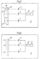
- the imaging optics 20 of the leveling device 13 differs from that Imaging optics 20 of the leveling device 12 from FIG. 3 by an additional attached diffractive optical element 29.
- the diffractive optical Element 29 corrects those from refractive pupil zones 21, 22 and 23 generated images. It can be made from a sheet of glass on which Surface diffractive structures evaporated or etched into the surface are. Such structures can also be found directly on the refractive pupil zones 21, 22 and 23 may be applied.
- the imaging optics of the leveling device 14 consist exclusively of a diffractive optic 30.
- the diffractive optic 30 is also different Pupil zones 31, 32 and 33 divided by diffraction Depth of field on the corresponding assigned detectors 5, 6 and 7 map.
- FIG. 7 there is an imaging optics 20 as in FIG. 5 and a detector 9 as shown in Fig.2.
- the partial areas 9a, 9b and 9c of the detector 9 are here assigned to the different imaging pupil zones 21, 22 and 23.
- the Prisms 55 and 56 serve as beam deflection elements for beam guidance between the pupil zones 21, 22 and 23 and the detector regions 9a, 9b and 9c.
- Electronics 40 'and a computing unit 41 are connected to detector 9 Control and evaluation purposes downstream.
- a headlight 60 provided for illuminating the object to be recorded and in Leveling device 15 integrated.
- the light source 61 of the headlight 60 can be in the Infrared emitting laser diode.
Description
In der EP 0 551 948-A1 wird ein Strichcode-Erfassungsgerät beschrieben, das mehrere Linsen verschiedener Brennweite beinhaltet. Die Strichcode werden in unterschiedlicher Entfernung am Gerät vorbeigeführt und die Linsen erzeugen Bilder des Strichcodes auf einem Detektor. Jeder Linse ist eine Blende zugeordnet. Das Gerät besitzt nur einen Detektor und es wird zu jeder Zeit nur ein Strichcode auf dem Detektor abgebildet.
Deshalb liegt der Erfindung die Aufgabe zugrunde, eine Vorrichtung für Nivellierzwecke zu entwickeln, die eine in beliebigen Entfernungen aufgestellte Nivellierlatte ohne Nachfokussierung und ohne eine mechanische Verstellung scharf abbildet.
- Fig.1
- eine schematische Darstellung eines Nivelliergeräts mit einer Abbildungsoptik mit einzelnen Aperturen und mit einzelnen ihnen zugeordneten Detektoren,
- Fig.2
- eine schematische Darstellung eines Nivelliergeräts mit einer Abbildungsoptik mit einzelnen Aperturen und mit einem gemeinsamen Detektor,
- Fig.3
- eine schematische Darstellung eines Nivelliergeräts mit einer in Pupillenzonen aufgeteilten Apertur mit refraktiven optischen Elementen und einzelnen Detektoren,
- Fig.4
- eine schematische Darstellung der Frontansicht des Nivelliergeräts aus Fig.3,
- Fig.5
- eine schematische Darstellung eines Nivelliergeräts mit einer in Pupillenzonen aufgeteilten Apertur mit refraktiven optischen Elementen und mit einem diffraktiven Korrekturelement,
- Fig.6
- eine schematische Darstellung eines Nivelliergeräts mit einem in Pupillenzonen aufgeteilten diffraktiven optischen Element als Abbildungsoptik,
- Fig.7
- eine schematische Darstellung eines Nivelliergeräts mit einer in Pupillenzonen aufgeteilten Apertur und einem gemeinsamen Detektor.
Claims (13)
- Vorrichtung für Nivellierzwecke mit einer Abbildungsoptik (1, 2, 3, 4; 20) und einem ortsauflösenden optoelektronischen Detektor (5, 6, 7, 8; 9) zur Bildaufnahme und mit einer Elektronik (40, 40') und einer Recheneinheit (41) zur Steuerung des Detektors (5, 6, 7, 8; 9) und zur Bildauswertung, dadurch gekennzeichnet, dass die Abbildungsoptik (1, 2, 3, 4; 20) für die Abbildung aus unterschiedlichen Entfernungsbereichen eine Mehrzahl von unterschiedlich abbildenden Pupillenzonen (1, 2, 3, 4; 21, 22, 23) aufweist und jeder einzelnen Pupillenzone (1, 2, 3, 4; 21, 22, 23) jeweils ein ortsauflösender optoelektronischer Detektor (5, 6, 7, 8) bzw. ein Teilbereich (9a, 9b, 9c) auf einem ortsauflösenden optoelektronischen Detektor (9) zugeordnet ist, so dass die Abbildungsoptik eine simultane Abbildung aus unterschiedlichen Entfernungsbereichen ermöglicht.
- Vorrichtung nach Anspruch 1, dadurch gekennzeichnet, daß die unterschiedlich abbildenden Pupillenzonen (1-4; 21-23) unterschiedlich große, fest eingestellte Brennweiten aufweisen.
- Vorrichtung nach Anspruch 1 oder 2, dadurch gekennzeichnet, daß die unterschiedlich abbildenden Pupillenzonen (1-4; 21-23) unterschiedlich große, fest eingestellte Bildweiten aufweisen.
- Vorrichtung nach Anspruch 1, dadurch gekennzeichnet, daß die unterschiedlich abbildenden Pupillenzonen (1-4; 21-23) gleich große, fest eingestellte Brennweiten, aber unterschiedlich große, fest eingestellte Bildweiten aufweisen.
- Vorrichtung nach einem der vorherigen Ansprüche, dadurch gekennzeichnet, daß die unterschiedlich abbildenden Pupillenzonen (1-4; 21-23) unterschiedlich große Öffnungsflächen (D1, D2, D3, D4; 21,22,23) aufweisen.
- Vorrichtung nach einem der vorherigen Ansprüche, dadurch gekennzeichnet, daß die unterschiedlich abbildenden Pupillenzonen (1-4; 21-23) unterschiedlich geformte Öffnungsflächen (D1, D2, D3, D4; 21,22,23) aufweisen.
- Vorrichtung nach einem der vorherigen Ansprüche, dadurch gekennzeichnet, daß die unterschiedlich abbildenden Pupillenzonen (1-4) durch einzelne, separat angeordnete Aperturen (1-4) dargestellt sind.
- Vorrichtung nach einem der Ansprüche 1 bis 6, dadurch gekennzeichnet, daß die unterschiedlich abbildenden Pupillenzonen (21-23) in einer einzigen Apertur (20) zusammengefaßt sind.
- Vorrichtung nach einem der vorherigen Ansprüche, dadurch gekennzeichnet, daß die unterschiedlich abbildenden Pupillenzonen (1-4; 21-23) durch refraktive (21,22,23) und / oder diffraktive (29; 30) optische Elemente dargestellt sind.
- Vorrichtung nach einem der vorhergehenden, dadurch gekennzeichnet, daß die Zuordnung durch strahlablenkende optische Mittel (51-54) erfolgt.
- Vorrichtung nach Anspruch 10, dadurch gekennzeichnet, daß die strahlablenkenden optischen Mittel durch Prismen (51-54) dargestellt sind.
- Vorrichtung nach einem der vorherigen Ansprüche, dadurch gekennzeichnet, daß ein Scheinwerfer (60) zur Beleuchtung des abzubildenden Objekts integriert ist.
- Vorrichtung nach Anspruch 12 dadurch gekennzeichnet, daß die Lichtquelle (61) des Scheinwerfers (60) eine Laserdiode (61) ist.
Applications Claiming Priority (3)
| Application Number | Priority Date | Filing Date | Title |
|---|---|---|---|
| DE19504039A DE19504039C1 (de) | 1995-02-08 | 1995-02-08 | Vorrichtung für Nivellierzwecke |
| DE19504039 | 1995-02-08 | ||
| PCT/EP1996/000197 WO1996024820A1 (de) | 1995-02-08 | 1996-01-18 | Vorrichtung für nivellierzwecke |
Publications (2)
| Publication Number | Publication Date |
|---|---|
| EP0808447A1 EP0808447A1 (de) | 1997-11-26 |
| EP0808447B1 true EP0808447B1 (de) | 2001-10-31 |
Family
ID=7753396
Family Applications (1)
| Application Number | Title | Priority Date | Filing Date |
|---|---|---|---|
| EP96901734A Expired - Lifetime EP0808447B1 (de) | 1995-02-08 | 1996-01-18 | Vorrichtung für nivellierzwecke |
Country Status (7)
| Country | Link |
|---|---|
| US (1) | US6081327A (de) |
| EP (1) | EP0808447B1 (de) |
| JP (1) | JP3555087B2 (de) |
| KR (1) | KR100408119B1 (de) |
| CA (1) | CA2209724C (de) |
| DE (2) | DE19504039C1 (de) |
| WO (1) | WO1996024820A1 (de) |
Cited By (1)
| Publication number | Priority date | Publication date | Assignee | Title |
|---|---|---|---|---|
| EP2224205A1 (de) | 2009-02-25 | 2010-09-01 | Leica Geosystems AG | Nivelliergerät und Verfahren zum Nivellieren |
Families Citing this family (7)
| Publication number | Priority date | Publication date | Assignee | Title |
|---|---|---|---|---|
| DE19833996C1 (de) * | 1998-07-29 | 1999-12-09 | Zeiss Carl Jena Gmbh | Elektronisches Nivellier und Verfahren zur Videoanzielung |
| DE10008769C1 (de) * | 2000-02-24 | 2001-09-27 | Zsp Geodaetische Sys Gmbh | Verfahren und Einrichtung zur Signalverarbeitung, insbesondere für Digitalnivelliere |
| GB0301923D0 (en) * | 2003-01-28 | 2003-02-26 | Qinetiq Ltd | Imaging system |
| DE10318580B4 (de) * | 2003-04-24 | 2005-08-18 | Eads Astrium Gmbh | Verfahren und Empfänger zur gleichzeitigen Erfassung und Auswertung von mindestens zwei elektromagnetischen Signalen |
| DE102009031562A1 (de) * | 2009-07-02 | 2011-01-05 | Valeo Schalter Und Sensoren Gmbh | Vorrichtung, Sensor und Verfahren zur visuellen Entfernungsbestimmung zu einem Objekt |
| EP2835613B1 (de) * | 2013-08-08 | 2019-01-16 | Hexagon Technology Center GmbH | Geodätisches Vermessungsgerät mit Mikrolinsenarray |
| DE102019214602B3 (de) * | 2019-09-24 | 2021-03-25 | Optocraft Gmbh | Kombinationsdetektor sowie Verfahren zur Detektion von visuellen und optischen Eigenschaften einer Optik und zugehörige Prüfvorrichtung für eine Optik |
Family Cites Families (9)
| Publication number | Priority date | Publication date | Assignee | Title |
|---|---|---|---|---|
| US4404594A (en) * | 1981-11-02 | 1983-09-13 | Itek Corporation | Imaging system with enlarged depth of field |
| CH676043A5 (de) * | 1983-12-30 | 1990-11-30 | Wild Leitz Ag | |
| DE3601179A1 (de) * | 1986-01-17 | 1987-07-23 | Nestle & Fischer | Nivelliersystem mit rotierendem laserstrahl |
| US4808804A (en) * | 1987-01-28 | 1989-02-28 | Symbol Technologies, Inc. | Bar code symbol readers with variable spot size and/or working distance |
| US5298989A (en) * | 1990-03-12 | 1994-03-29 | Fujitsu Limited | Method of and apparatus for multi-image inspection of bonding wire |
| JPH0799529B2 (ja) * | 1991-01-15 | 1995-10-25 | インターナショナル・ビジネス・マシーンズ・コーポレイション | 画像認識装置及び画像検出方法 |
| DE69320708T3 (de) * | 1992-06-24 | 2005-07-28 | Kabushiki Kaisha Topcon | Elektronisches Höhenmessgerät mit Höhenmesslatte |
| US5627366A (en) * | 1995-05-19 | 1997-05-06 | Symbol Technologies, Inc. | Optical scanner with extended depth of focus |
| US5770843A (en) * | 1996-07-02 | 1998-06-23 | Ncr Corporation | Access card for multiple accounts |
-
1995
- 1995-02-08 DE DE19504039A patent/DE19504039C1/de not_active Expired - Lifetime
-
1996
- 1996-01-18 CA CA002209724A patent/CA2209724C/en not_active Expired - Lifetime
- 1996-01-18 KR KR1019970703877A patent/KR100408119B1/ko not_active IP Right Cessation
- 1996-01-18 EP EP96901734A patent/EP0808447B1/de not_active Expired - Lifetime
- 1996-01-18 WO PCT/EP1996/000197 patent/WO1996024820A1/de active IP Right Grant
- 1996-01-18 DE DE59608072T patent/DE59608072D1/de not_active Expired - Lifetime
- 1996-01-18 JP JP52392296A patent/JP3555087B2/ja not_active Expired - Lifetime
- 1996-01-18 US US08/836,877 patent/US6081327A/en not_active Expired - Lifetime
Cited By (3)
| Publication number | Priority date | Publication date | Assignee | Title |
|---|---|---|---|---|
| EP2224205A1 (de) | 2009-02-25 | 2010-09-01 | Leica Geosystems AG | Nivelliergerät und Verfahren zum Nivellieren |
| WO2010097346A1 (de) | 2009-02-25 | 2010-09-02 | Leica Geosystems Ag | Nivelliergerät und verfahren zum nivellieren |
| US8539686B2 (en) | 2009-02-25 | 2013-09-24 | Leica Geosystems Ag | Leveling device and leveling method |
Also Published As
| Publication number | Publication date |
|---|---|
| DE59608072D1 (de) | 2001-12-06 |
| WO1996024820A1 (de) | 1996-08-15 |
| DE19504039C1 (de) | 1996-04-04 |
| JPH11501117A (ja) | 1999-01-26 |
| CA2209724C (en) | 2001-09-25 |
| CA2209724A1 (en) | 1996-08-15 |
| EP0808447A1 (de) | 1997-11-26 |
| KR100408119B1 (ko) | 2004-01-24 |
| US6081327A (en) | 2000-06-27 |
| JP3555087B2 (ja) | 2004-08-18 |
Similar Documents
| Publication | Publication Date | Title |
|---|---|---|
| EP2835613B1 (de) | Geodätisches Vermessungsgerät mit Mikrolinsenarray | |
| DE3424806C2 (de) | ||
| DE19949580B4 (de) | Autofokuseinrichtung für ein Visierfernrohr | |
| DE3828381C2 (de) | Verfahren und Einrichtung zur automatischen Fokussierung eines optischen Systems | |
| EP2405236B1 (de) | Geodätisches Vermessungsgerät mit automatischer hochpräziser Zielpunkt-Anzielfunktionalität | |
| DE4131737C2 (de) | Autofokus-Anordnung für ein Stereomikroskop | |
| DE102013006994A1 (de) | Digitalmikroskop und Verfahren zur Optimierung des Arbeitsablaufes in einem Digitalmikroskop | |
| EP3781899B1 (de) | Optische messeinrichtung sowie verfahren zum vermessen eines optischen elements | |
| EP2401576B1 (de) | Nivelliergerät und verfahren zum nivellieren | |
| EP1287397A2 (de) | Anordnung zur konfokalen autofokussierung | |
| EP0808447B1 (de) | Vorrichtung für nivellierzwecke | |
| DE19823076B4 (de) | Vermessungsinstrument | |
| EP0466979B1 (de) | Anordnung zur simultanen konfokalen Bilderzeugung | |
| DE102005022125A1 (de) | Lichtrastermikroskop mit Autofokusmechanismus | |
| EP1186928B1 (de) | Parallelverarbeitender optischer Entfernungsmesser | |
| DE4121145C2 (de) | Objektdetektionssystem für optisches Instrument | |
| DE10056329B4 (de) | Optisches Abstandsmeßverfahren und Abstandssensor | |
| EP1293817B1 (de) | Vorrichtung und Verfahren zur Fokuskontrolle in einem Mikroskop mit digitaler Bildgebung, vorzugsweise einem konfokalen Mikroskop | |
| DE102019102330B3 (de) | Optisches System für ein Mikroskop, Mikroskop mit einem optischen System und Verfahren zur Abbildung eines Objekts unter Verwendung eines Mikroskops | |
| DE102009012248A1 (de) | Autofokusverfahren und Abbildungsvorrichtung zur Durchführung des Verfahrens | |
| DE10234756B3 (de) | Autofokusmodul für mikroskopbasierte Systeme | |
| EP0709652B1 (de) | Verfahren zur Bestimmung des Kippwinkels von codierten Nivellierlatten | |
| DE19822869A1 (de) | Optisches Nahfeldmikroskop | |
| EP2767797B1 (de) | Niedrigkohärenzinterferometer und Verfahren zur ortsaufgelösten optischen Vermessung des Oberflächenprofils eines Objekts | |
| EP1179748B1 (de) | Kombination von abtastenden und abbildenden Methoden bei der Überprüfung von Photomasken |
Legal Events
| Date | Code | Title | Description |
|---|---|---|---|
| PUAI | Public reference made under article 153(3) epc to a published international application that has entered the european phase |
Free format text: ORIGINAL CODE: 0009012 |
|
| 17P | Request for examination filed |
Effective date: 19970711 |
|
| AK | Designated contracting states |
Kind code of ref document: A1 Designated state(s): CH DE FR GB LI SE |
|
| RAP1 | Party data changed (applicant data changed or rights of an application transferred) |
Owner name: LEICA GEOSYSTEMS AG |
|
| 17Q | First examination report despatched |
Effective date: 19990907 |
|
| GRAG | Despatch of communication of intention to grant |
Free format text: ORIGINAL CODE: EPIDOS AGRA |
|
| GRAG | Despatch of communication of intention to grant |
Free format text: ORIGINAL CODE: EPIDOS AGRA |
|
| GRAH | Despatch of communication of intention to grant a patent |
Free format text: ORIGINAL CODE: EPIDOS IGRA |
|
| GRAH | Despatch of communication of intention to grant a patent |
Free format text: ORIGINAL CODE: EPIDOS IGRA |
|
| GRAA | (expected) grant |
Free format text: ORIGINAL CODE: 0009210 |
|
| AK | Designated contracting states |
Kind code of ref document: B1 Designated state(s): CH DE FR GB LI SE |
|
| REG | Reference to a national code |
Ref country code: CH Ref legal event code: EP |
|
| REF | Corresponds to: |
Ref document number: 59608072 Country of ref document: DE Date of ref document: 20011206 |
|
| REG | Reference to a national code |
Ref country code: CH Ref legal event code: NV Representative=s name: BUECHEL, KAMINSKI & PARTNER PATENTANWAELTE ESTABLI |
|
| REG | Reference to a national code |
Ref country code: GB Ref legal event code: IF02 |
|
| GBT | Gb: translation of ep patent filed (gb section 77(6)(a)/1977) |
Effective date: 20020106 |
|
| ET | Fr: translation filed | ||
| PLBE | No opposition filed within time limit |
Free format text: ORIGINAL CODE: 0009261 |
|
| STAA | Information on the status of an ep patent application or granted ep patent |
Free format text: STATUS: NO OPPOSITION FILED WITHIN TIME LIMIT |
|
| 26N | No opposition filed | ||
| REG | Reference to a national code |
Ref country code: CH Ref legal event code: PFA Owner name: LEICA GEOSYSTEMS AG Free format text: LEICA GEOSYSTEMS AG# #9435 HEERBRUGG (CH) -TRANSFER TO- LEICA GEOSYSTEMS AG# #9435 HEERBRUGG (CH) |
|
| REG | Reference to a national code |
Ref country code: FR Ref legal event code: PLFP Year of fee payment: 20 |
|
| PGFP | Annual fee paid to national office [announced via postgrant information from national office to epo] |
Ref country code: DE Payment date: 20150121 Year of fee payment: 20 Ref country code: CH Payment date: 20150121 Year of fee payment: 20 |
|
| PGFP | Annual fee paid to national office [announced via postgrant information from national office to epo] |
Ref country code: FR Payment date: 20150122 Year of fee payment: 20 Ref country code: GB Payment date: 20150121 Year of fee payment: 20 Ref country code: SE Payment date: 20150121 Year of fee payment: 20 |
|
| REG | Reference to a national code |
Ref country code: DE Ref legal event code: R071 Ref document number: 59608072 Country of ref document: DE |
|
| REG | Reference to a national code |
Ref country code: CH Ref legal event code: PL |
|
| REG | Reference to a national code |
Ref country code: GB Ref legal event code: PE20 Expiry date: 20160117 |
|
| REG | Reference to a national code |
Ref country code: SE Ref legal event code: EUG |
|
| PG25 | Lapsed in a contracting state [announced via postgrant information from national office to epo] |
Ref country code: GB Free format text: LAPSE BECAUSE OF EXPIRATION OF PROTECTION Effective date: 20160117 |