EP0808059A2 - Appareil de compensation de mouvement - Google Patents
Appareil de compensation de mouvement Download PDFInfo
- Publication number
- EP0808059A2 EP0808059A2 EP19970112635 EP97112635A EP0808059A2 EP 0808059 A2 EP0808059 A2 EP 0808059A2 EP 19970112635 EP19970112635 EP 19970112635 EP 97112635 A EP97112635 A EP 97112635A EP 0808059 A2 EP0808059 A2 EP 0808059A2
- Authority
- EP
- European Patent Office
- Prior art keywords
- motion
- field
- signal
- precedent
- motion compensation
- Prior art date
- Legal status (The legal status is an assumption and is not a legal conclusion. Google has not performed a legal analysis and makes no representation as to the accuracy of the status listed.)
- Granted
Links
Images


Classifications
-
- H—ELECTRICITY
- H04—ELECTRIC COMMUNICATION TECHNIQUE
- H04N—PICTORIAL COMMUNICATION, e.g. TELEVISION
- H04N5/00—Details of television systems
- H04N5/14—Picture signal circuitry for video frequency region
- H04N5/144—Movement detection
- H04N5/145—Movement estimation
-
- H—ELECTRICITY
- H04—ELECTRIC COMMUNICATION TECHNIQUE
- H04N—PICTORIAL COMMUNICATION, e.g. TELEVISION
- H04N19/00—Methods or arrangements for coding, decoding, compressing or decompressing digital video signals
- H04N19/10—Methods or arrangements for coding, decoding, compressing or decompressing digital video signals using adaptive coding
- H04N19/102—Methods or arrangements for coding, decoding, compressing or decompressing digital video signals using adaptive coding characterised by the element, parameter or selection affected or controlled by the adaptive coding
- H04N19/103—Selection of coding mode or of prediction mode
- H04N19/105—Selection of the reference unit for prediction within a chosen coding or prediction mode, e.g. adaptive choice of position and number of pixels used for prediction
-
- H—ELECTRICITY
- H04—ELECTRIC COMMUNICATION TECHNIQUE
- H04N—PICTORIAL COMMUNICATION, e.g. TELEVISION
- H04N19/00—Methods or arrangements for coding, decoding, compressing or decompressing digital video signals
- H04N19/10—Methods or arrangements for coding, decoding, compressing or decompressing digital video signals using adaptive coding
- H04N19/102—Methods or arrangements for coding, decoding, compressing or decompressing digital video signals using adaptive coding characterised by the element, parameter or selection affected or controlled by the adaptive coding
- H04N19/103—Selection of coding mode or of prediction mode
- H04N19/112—Selection of coding mode or of prediction mode according to a given display mode, e.g. for interlaced or progressive display mode
-
- H—ELECTRICITY
- H04—ELECTRIC COMMUNICATION TECHNIQUE
- H04N—PICTORIAL COMMUNICATION, e.g. TELEVISION
- H04N19/00—Methods or arrangements for coding, decoding, compressing or decompressing digital video signals
- H04N19/10—Methods or arrangements for coding, decoding, compressing or decompressing digital video signals using adaptive coding
- H04N19/134—Methods or arrangements for coding, decoding, compressing or decompressing digital video signals using adaptive coding characterised by the element, parameter or criterion affecting or controlling the adaptive coding
- H04N19/136—Incoming video signal characteristics or properties
- H04N19/137—Motion inside a coding unit, e.g. average field, frame or block difference
-
- H—ELECTRICITY
- H04—ELECTRIC COMMUNICATION TECHNIQUE
- H04N—PICTORIAL COMMUNICATION, e.g. TELEVISION
- H04N19/00—Methods or arrangements for coding, decoding, compressing or decompressing digital video signals
- H04N19/42—Methods or arrangements for coding, decoding, compressing or decompressing digital video signals characterised by implementation details or hardware specially adapted for video compression or decompression, e.g. dedicated software implementation
- H04N19/43—Hardware specially adapted for motion estimation or compensation
-
- H—ELECTRICITY
- H04—ELECTRIC COMMUNICATION TECHNIQUE
- H04N—PICTORIAL COMMUNICATION, e.g. TELEVISION
- H04N19/00—Methods or arrangements for coding, decoding, compressing or decompressing digital video signals
- H04N19/50—Methods or arrangements for coding, decoding, compressing or decompressing digital video signals using predictive coding
- H04N19/503—Methods or arrangements for coding, decoding, compressing or decompressing digital video signals using predictive coding involving temporal prediction
- H04N19/51—Motion estimation or motion compensation
- H04N19/523—Motion estimation or motion compensation with sub-pixel accuracy
-
- H—ELECTRICITY
- H04—ELECTRIC COMMUNICATION TECHNIQUE
- H04N—PICTORIAL COMMUNICATION, e.g. TELEVISION
- H04N19/00—Methods or arrangements for coding, decoding, compressing or decompressing digital video signals
- H04N19/50—Methods or arrangements for coding, decoding, compressing or decompressing digital video signals using predictive coding
- H04N19/503—Methods or arrangements for coding, decoding, compressing or decompressing digital video signals using predictive coding involving temporal prediction
- H04N19/51—Motion estimation or motion compensation
- H04N19/577—Motion compensation with bidirectional frame interpolation, i.e. using B-pictures
-
- H—ELECTRICITY
- H04—ELECTRIC COMMUNICATION TECHNIQUE
- H04N—PICTORIAL COMMUNICATION, e.g. TELEVISION
- H04N23/00—Cameras or camera modules comprising electronic image sensors; Control thereof
- H04N23/60—Control of cameras or camera modules
- H04N23/68—Control of cameras or camera modules for stable pick-up of the scene, e.g. compensating for camera body vibrations
- H04N23/681—Motion detection
- H04N23/6811—Motion detection based on the image signal
-
- H—ELECTRICITY
- H04—ELECTRIC COMMUNICATION TECHNIQUE
- H04N—PICTORIAL COMMUNICATION, e.g. TELEVISION
- H04N23/00—Cameras or camera modules comprising electronic image sensors; Control thereof
- H04N23/60—Control of cameras or camera modules
- H04N23/68—Control of cameras or camera modules for stable pick-up of the scene, e.g. compensating for camera body vibrations
- H04N23/682—Vibration or motion blur correction
- H04N23/683—Vibration or motion blur correction performed by a processor, e.g. controlling the readout of an image memory
-
- H—ELECTRICITY
- H04—ELECTRIC COMMUNICATION TECHNIQUE
- H04N—PICTORIAL COMMUNICATION, e.g. TELEVISION
- H04N7/00—Television systems
- H04N7/01—Conversion of standards, e.g. involving analogue television standards or digital television standards processed at pixel level
- H04N7/0102—Conversion of standards, e.g. involving analogue television standards or digital television standards processed at pixel level involving the resampling of the incoming video signal
Definitions
- This invention generally relates to an apparatus for performing a highly efficient coding or an image standards conversion, which is for use in a system for recording, transmitting and displaying digital image signals. More particularly, this invention relates to a motion compensation apparatus for receiving information on motion vectors and for performing a motion compensation (or movement compensation) of dynamic image signals with precision that is equal to or finer than an interval or a distance (hereunder sometimes referred to simply as a pixel interval or distance) between two adjoining pixels.
- a typical method for performing a highly efficient coding of dynamic image signals is an interframe prediction coding method, by which a frame to be coded is predicted from a previous frame already coded and only a coding of prediction error is performed.
- an interframe prediction coding method by which a frame to be coded is predicted from a previous frame already coded and only a coding of prediction error is performed.
- a motion-compensated interframe prediction for effecting the prediction by changing an image in accordance with the motion of a moving object has come to be generally performed.
- a motion compensation operation is merely to shift the position of a pixel.
- a motion compensation signal is generated by effecting a resampling processing.
- Such a processing can be more appropriately done by performing a prediction and an interpolation by using a plurality of frames.
- FIG. 4 there is shown the configuration of an example of a conventional motion compensation apparatus which performs a motion compensation on a reference image to be processed, namely, a reference field with high precision from two fields (hereunder sometimes referred to as precedent and subsequent fields) respectively precedent and subsequent to the reference field.
- a precedent field signal representing a precedent field is input from a precedent-field-signal input terminal 3 to both of a motion vector (MV) estimating device 5 and a pixel shifting device 7, and on the other hand a subsequent field signal representing a subsequent field is input from a subsequent-field-signal input terminal 4 to both of another MV estimating device 6 and a pixel shifting device 8.
- a reference field signal representing the reference field is input from a reference-image input terminal 2 to both of the MV estimating devices 5 and 6.
- motion vectors representing the displacement of a moving object which is shown in a dynamic image (namely, the reference image) between the precedent and reference fields are estimated from the precedent field signal and the reference field signal.
- motion vectors representing the displacement of the moving object between the reference and subsequent fields are estimated from the reference field signal and the subsequent field signal.
- Such motion vectors are estimated by performing a pattern matching process (namely, what is called a block matching process) on each block, which consists of 16 ⁇ 16 pixels, of the reference field, namely, by evaluating predetermined measure of the prediction error corresponding to a block of the reference field and blocks of the precedent or subsequent field, which are indicated by what is called trial motion vectors, and then determining one of the trial motion vectors corresponding to a minimum prediction error as the motion vector corresponding to the block of the reference field and effecting such a process on each of the other blocks of the reference field.
- a pattern matching process namely, what is called a block matching process
- signals representing the motion vectors estimated by the MV estimating device 5 are output therefrom through a precedent MV output terminal 11 to another circuit and moreover are supplied to the pixel shifting device 7 and a micro-shift device 17.
- signals representing the motion vectors estimated by the MV estimating device 6 are output therefrom through a subsequent MV output terminal 12 to another circuit and moreover are supplied to the pixel shifting device 8 and a micro-shift device 18.
- a decoding system in a coding system, it is necessary for performing a decoding processing later to output the motion vectors.
- the motion compensation apparatus it is not necessary for the motion compensation apparatus to output the motion vectors because the image conversion system has only to obtain motion-compensated image signals.
- a decoding system does not estimate motion vectors but receives information on motion vectors from a coding system.
- a pixel represented by the precedent field signal is shifted on the basis of the precedent motion vector with precision that is equal to the pixel interval. Then, a signal representing the shifted pixel is fed to the micro-shift device 17. Subsequently, to perform a resampling processing, the micro-shift device 17 multiplies data representing each of such pixels by a coefficient corresponding to a motion represented with accuracy to the pixel interval and further adds results of such multiplications up. Namely, among information on the motion vectors, part of such information represented with precision, which is equal to or finer than the pixel interval, is used by the pixel shifting device 7. Further, the remaining part of such information represented with precision, which is finer than the pixel interval, is used by the micro-shift device 17. The thus motion-compensated precedent-field signal is supplied to an adder 14.
- a pixel represented by the subsequent field signal is shifted on the basis of the subsequent motion vector with precision that is equal to the pixel interval.
- the micro-shift device 18 multiplies data representing each of the shifted pixels by a coefficient corresponding to a motion represented with accuracy to the pixel interval and further adds results of such multiplications up. Further, the micro-shift device 18 supplies signals representing results of such operations as the thus motion-compensated subsequent-field signal to the adder 14.
- the adder 14 adds both of data respectively represented by the thus motion-compensated precedent-field and subsequent-field signals and outputs a signal representing a result of this addition as a motion-compensated signal through a motion-compensated-signal output terminal 15 to another circuit.
- each field signal is obtained by "thinning out” a frame signal and therefore contains many aliasing frequency-components (hereunder sometimes referred to as aliasing components).
- each field signal includes aliasing components if the diameter of an electron beam of a television camera is smaller than the interval between adjoining scanning lines.
- the present invention is accomplished to eliminate such a defect of the conventional motion compensation apparatus.
- an object of the present invention to provide a motion compensation apparatus which can obtain more suitably motion-compensated signals as a result of generating image signals, the density of which is higher than that of field signals, by adding up the field signals when high-precision motion-compensated signals are obtained from a plurality of fields, and then performing a resampling processing on the image signals by using resampling coefficients corresponding thereto.
- each field signal is used as a sub-sampled part of image signals, the density of which is higher than that of each field signal, instead of effecting a filtering, namely, a resampling of each field.
- a resampling is performed on high-density image signals generated by adding field signals. Namely, once, high-density image signals are virtually produced. Then, the pixels represented by the generated image signals are shifted by the resampling. Thereafter, the image signals obtained as the result of shifting the pixels are thinned out. Practically, the same effects of such an operation can be achieved by employing high-density resampling coefficients.
- motion-compensated signals are used in an interframe (or interfield) predictive coding
- prediction error decreases with the result that data quantity can be further reduced.
- motion-compensated signals are used in a scanning-line interpolation or a field interpolation, a natural and high-resolution image can be obtained.
- the motion compensation apparatus can obtain practically distinguished effects or advantages.
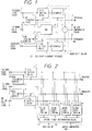
- FIG. 1 is a schematic block diagram for illustrating the configuration of a motion compensation apparatus embodying the present invention (namely, a first embodiment of the present invention).
- This embodiment is different in an employed method for generating filtering coefficients, by which data on pixels are multiplied to perform a motion compensation with precision that is equal to or finer than a pixel distance (namely, the distance between adjoining pixels), from the conventional motion compensation apparatus.
- the first embodiment is not different in a method for estimating motion vectors and in a manner of shifting the pixels with accuracy, which is equal to the pixel distance, from the conventional motion compensation apparatus.
- Precedent field signals input from a precedent field input terminal 3 are further input to a precedent MV estimating device 5 and a pixel shifting device 7.
- subsequent field signals input from a subsequent field input terminal 4 are further input to a precedent MV estimating device 6 and a pixel shifting device 8.
- reference field signals input from a reference image input terminal 2 are further input to both of the MV estimating devices 5 and 6.
- a precedent motion vector corresponding to the motion of an object between the reference field (or frame) and a precedent field is obtained from the precedent signal and a reference field signal (or reference frame signal).
- a subsequent motion vector corresponding to the motion of the object between the reference field and a subsequent field is obtained from the reference signal and a reference field signal.
- a signal representing the precedent motion vector obtained by and output from the MV estimating device 5 is output from the motion compensation apparatus through a precedent MV output terminal 11 to another circuit and is further applied to a pixel shifting device 7 and a coefficient determination device 13 of a micro-shift portion 1.
- a signal representing the subsequent motion vector obtained by and output from the MV estimating device 6 is output from the motion compensation apparatus through a subsequent MV output terminal 12 to another circuit and is further applied to a pixel shifting device 8 and the coefficient determination device 13.
- pixels represented by the precedent field signals are shifted with the accuracy, which is equal to one pixel, according to the precedent motion vector. Further, a signal representing a result of the shifting of the pixels is supplied to a re-sampler 9 of the micro-shift portion 1. Similarly, in the pixel shifting device 8, pixels represented by the subsequent field signals are shifted with the accuracy, which is equal to one pixel, according to the subsequent motion vector. Further, a signal representing a result of this shifting of the pixels is supplied to a re-sampler 10.
- resampling-and-filtering coefficients are determined by looking up a coefficient table according to the values equal to or less than a pixel distance, which are respectively indicated by both of the motion vectors.
- a signal representing the determined resampling-and-filtering coefficient is output therefrom to the re-samplers 9 and 10.
- the contents of the coefficient table are preliminarily written to a read-only memory (ROM) and are read therefrom by using a value indicated by the motion vector as an address thereof.
- the re-sampler 9 of the micro-shift portion 1 performs a motion compensation on the precedent field signal, each corresponding pixel of which has already undergone the shifting, with the accuracy equal to or less than one pixel by using the coefficients indicated by the received signal.
- the thus processed signal is fed to an adder 14 of the micro-shift portion.
- the re-sampler 10 of the micro-shift portion 1 effects a motion compensation on the subsequent field signal, each corresponding pixel of which has already undergone the shifting, with the accuracy equal to or less than one pixel by using the coefficients indicated by the received signal.
- the signal thus processed in the re-sampler 10 is supplied to the adder 14. Thereafter, the adder 14 adds values respectively represented by the signals received from the samplers 9 and 10 and outputs a signal indicating a result of this addition as a motion-compensated signal through a motion-compensated signal output terminal 15.
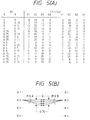
- the resampling-and-filtering coefficient cannot be determined according to the motion vectors supplied only from one of the MV estimating devices 5 and 6. Namely, the combination of the motion vectors respectively supplied from the MV estimating devices 5 and 6 is necessary for determining the coefficients. Examples of such coefficients are shown in FIG. 5(A). Further, a portion of a resampling-and-filtering response in case of an example of the combination of the coefficients respectively corresponding to the precedent motion vector and the subsequent motion vector is shown in FIG. 6(B). Incidentally, a portion of a resampling-and-filtering response of a conventional motion compensation apparatus is shown in FIG. 6(A) to be compared with the response of FIG. 6(B).
- sub-columns A and B of a column MV indicate the values equal to or less than the pixel distance respectively represented by the precedent motion vector and the subsequent motion vector with the precision equal to (1/4) pixel (namely, one-fourth pixel distance).
- the values indicated by the sub-columns A and B will be referred to as values MVA and MVB, respectively.
- MVA and MVB There are four kinds of values used as each of the values MVA and MVB.
- Reference characters A1 to A4 denote the values of the coefficients corresponding to the precedent field signal, and on the other hand, reference characters B1 to B4 denote the values of the coefficients corresponding to the subsequent field signal.
- FIG. 5(B) shows the relation between a motion vector and each of the positions of pixels.
- FIGS. 6(A) and 6(B) illustrate an example of a resampling-and-filtering response of the conventional motion compensation apparatus and an example of a resampling-and-filtering response of this embodiment of the present invention in case where the values MVA and MVB are 0.75 and 0.25, respectively.
- the resampling is performed on each field.
- the resampling-and-filtering response in case of the conventional motion apparatus has a gently sloping form.
- the resampling is effected by using pixels of both of the two fields.
- the resampling-and-filtering response in case of this embodiment has a sharp form corresponding to sampling points, the density of which is higher than that of sampling points of the conventional motion compensation apparatus.
- This utilizes the fact that the position of a pixel of a moving object in one of the two fields is different from that of a corresponding pixel of the moving object in the other field. If the position of a pixel of one of the two fields is in agreement with that of a corresponding pixel of the other field, the same response is obtained. However, if the center of one of the two fields is shifted to, for example, the very center of the other field, the density of the sampling points of this embodiment of the present invention becomes twice that of the sampling points in case of using the conventional motion compensation apparatus.
- the frequency characteristics of a motion-compensated signal are improved and the output level thereof becomes twice that of a motion-compensated signal generated by the conventional motion compensation apparatus at the maximum. Further, aliasing components included in each field signal are reduced. Thus, even when performing a resampling, a suitable motion-compensated signal can be obtained. Consequently, a field signal obtained by thinning out of such a motion-compensated signal contains only tolerable aliasing components. Therefore, a prediction or an interpolation can be appropriately performed even when such a field signal is used in the prediction or the interpolation.
- FIG. 2 is a schematic block diagram for illustrating the configuration of another motion compensation apparatus embodying the present invention (namely, a second embodiment of the present invention).
- the second embodiment has a plurality of micro-shift portions 21 to 24, as well as an optimal signal determination device 25.
- each of the micro-shift portions 21 to 24 is similar to the micro-shift portion 1 consisting of the re-samplers 9 and 10, the coefficient determination device 13 and the adder 14 as indicated by dashed lines in FIG. 1.
- the micro-shift portions 21 to 24 are different in coefficients generated in the coefficient determination device from one another.
- operations of the MV estimating devices 5 and 6 and the pixel shifting devices 7 and 8 are the same as the above described operations of the corresponding devices of the first embodiment of FIG. 1.
- each of the micro-shift portions 21 to 24 serves to make a more accurate determination by using the high-density signals.
- the coefficients determined by each of the micro-shift portions 21 to 24 correspond to motion vectors which are different from one another minutely.
- each of the micro-shift portions 21 to 24 Signals representing a precedent field signal, a subsequent field signal, a precedent MV and a subsequent MV are input to the micro-shift portions 21 to 24.
- the inside structure or configuration of each of the micro-shift portions 21 to 24 is similar to that of the micro-shift portion 1 as indicated by dashed lines of FIG. 1.
- fundamental operations of each of the micro-shift portions 21 to 24 are similar to those of the portion 1 of FIG. 1 except the coefficients output by the coefficient determination device of each of the micro-shift portions 21 to 24.
- such coefficients are obtained by each of the micro-shift portions 21 to 24 by being shifted minutely correspondingly to two motion vectors input thereto.
- the coefficients of groups respectively output by the micro-shift portions 21 to 24 correspond to four kinds of combinations of the values MVA and MVB (for instance, 0 and 0; 0 and 0.25; 0,25 and 0; and 0.25 and 0.25).
- each motion vector has a vertical component and a horizontal component
- a result of the estimation which can be sufficiently estimated in each of the fields by the MV estimating device, is used as the horizontal component and that the micro-shift portions deal with only the vertical component.
- an output signal of each of the micro-shift portions 21 to 24 is input to an optimal signal determination device 25.
- the optimal signal determination device 25 checks how a corresponding motion-compensated signal matches a reference field signal. Further, the optimal signal determination device 25 selects the motion-compensated signal which matches the reference field signal the best of all of those output from the micro-shift portions 21 to 24 (namely, the optimal signal determination device 25 selects the motion-compensated signal having a smallest error). The selected signal is output through the motion-compensated signal output terminal 15 as an ultimate motion-compensated signal.
- Such a selection operation is similar to the MV estimation operation.
- the number of signals to be checked in the selection operation is far smaller than that of the vectors to be checked in the MV estimation operation. Therefore, the selection operation can be performed more thoroughly in comparison with the MV estimation operation.
- an absolute value of an error MAD
- MSE mean square error
- motion-vector modification information which indicates the micro-shift portion outputting the selected signal, is output through a modified MV output terminal 26.
- FIG. 3 is a schematic block diagram for illustrating the configuration of a further motion compensation apparatus embodying the present invention (namely, a third embodiment of the present invention).
- a further motion compensation apparatus embodying the present invention namely, a third embodiment of the present invention.
- the differences between the second embodiment of FIG. 2 and the third embodiment of FIG. 3 reside in that micro-shift portions 31 to 34 of the third embodiment do not receive vector information and that the number of the micro-shift portions of the third embodiment is rather large.
- the technical idea employed in the second embodiment is furthered or promoted. Namely, in each of MV estimating devices 19 and 20, the estimation of motion vectors is performed on each field with the precision to one pixel. Further, a motion compensation is performed with the precision equal to or finer than one pixel by micro-shift portions 31 to 34 and an optimal signal determination device 25 by using both of two fields (namely, a precedent and subsequent fields).
- each of the re-samplers 31 to 34 is similar to that of the re-sampler of FIG. 1. However, no motion vectors are input to the coefficient determination device 13 of each of the micro-shift portions 31 to 34 and moreover signals representing fixed coefficients are output therefrom.
- micro-MV output terminal 27 information on a motion-vector having the magnitude less than one pixel, which indicates the micro-shift portion outputting a selected signal, is output through a micro-MV output terminal 27.
- a motion compensation apparatus of the present invention which is for use in a decoder of a coding system, does not effect an estimation of motion vectors but receives information on motion vectors from an encoder.
- the configuration of the fourth embodiment is similar to that of the first embodiment of FIG. 1 except that a reference signal input terminal 2 and MV estimating devices 5 and 6 are removed therefrom.
- Information on both of precedent and subsequent motion vectors is input and is supplied directly to a coefficient determination device 13.
- operations of pixel shifting devices 7 and 8 and a micro-shift portion 1 are similar to those of the corresponding elements of the first embodiment of FIG. 1.
- the present invention discloses a motion compensation apparatus for receiving information on motion vectors and for performing a motion compensation of dynamic image signals with precision equal to or finer than one pixel.
- the information on motion vectors has been estimated from a reference field or frame represented by a reference field signal or a reference frame signal and other fields or other frames represented by other field signals or frame signals.
- the motion compensation apparatus is provided with a coefficient determination device for determining resampling coefficients corresponding to signals which are generated by adding the other field (or frame) signals according to relations among the motion vectors and image shifting devices for resampling and adding up the field (or frame) signals by using the sampling coefficients to obtain image signals representing shifted pixels, which are motion-compensated with precision that is equal to or finer than one pixel.
Landscapes
- Engineering & Computer Science (AREA)
- Multimedia (AREA)
- Signal Processing (AREA)
- Television Systems (AREA)
- Image Processing (AREA)
- Color Television Systems (AREA)
- Compression Or Coding Systems Of Tv Signals (AREA)
Applications Claiming Priority (4)
| Application Number | Priority Date | Filing Date | Title |
|---|---|---|---|
| JP313607/91 | 1991-10-31 | ||
| JP31360791 | 1991-10-31 | ||
| JP31360791A JP2611591B2 (ja) | 1991-10-31 | 1991-10-31 | 動き補償装置 |
| EP19920118692 EP0544122B1 (fr) | 1991-10-31 | 1992-10-30 | Dispositif pour compenser des mouvements dans des images |
Related Parent Applications (2)
| Application Number | Title | Priority Date | Filing Date |
|---|---|---|---|
| EP19920118692 Division EP0544122B1 (fr) | 1991-10-31 | 1992-10-30 | Dispositif pour compenser des mouvements dans des images |
| EP92118692.0 Division | 1992-10-30 |
Publications (3)
| Publication Number | Publication Date |
|---|---|
| EP0808059A2 true EP0808059A2 (fr) | 1997-11-19 |
| EP0808059A3 EP0808059A3 (fr) | 1998-04-29 |
| EP0808059B1 EP0808059B1 (fr) | 2002-01-09 |
Family
ID=18043359
Family Applications (2)
| Application Number | Title | Priority Date | Filing Date |
|---|---|---|---|
| EP19920118692 Expired - Lifetime EP0544122B1 (fr) | 1991-10-31 | 1992-10-30 | Dispositif pour compenser des mouvements dans des images |
| EP97112635A Expired - Lifetime EP0808059B1 (fr) | 1991-10-31 | 1992-10-30 | Appareil de compensation de mouvement |
Family Applications Before (1)
| Application Number | Title | Priority Date | Filing Date |
|---|---|---|---|
| EP19920118692 Expired - Lifetime EP0544122B1 (fr) | 1991-10-31 | 1992-10-30 | Dispositif pour compenser des mouvements dans des images |
Country Status (5)
| Country | Link |
|---|---|
| US (1) | US5355168A (fr) |
| EP (2) | EP0544122B1 (fr) |
| JP (1) | JP2611591B2 (fr) |
| DE (2) | DE69232341T2 (fr) |
| HK (1) | HK1000864A1 (fr) |
Families Citing this family (28)
| Publication number | Priority date | Publication date | Assignee | Title |
|---|---|---|---|---|
| JP2611591B2 (ja) * | 1991-10-31 | 1997-05-21 | 日本ビクター株式会社 | 動き補償装置 |
| JPH05336514A (ja) * | 1992-05-29 | 1993-12-17 | Sony Corp | 画像符号化装置 |
| US5461423A (en) * | 1992-05-29 | 1995-10-24 | Sony Corporation | Apparatus for generating a motion vector with half-pixel precision for use in compressing a digital motion picture signal |
| JPH06113287A (ja) * | 1992-09-30 | 1994-04-22 | Matsushita Electric Ind Co Ltd | 画像符号化装置と画像復号化装置 |
| KR0166724B1 (ko) * | 1993-05-08 | 1999-03-20 | 김광호 | 반화소정확도를 갖는 동벡터추정방법 및 그 장치 |
| EP0644698A3 (fr) * | 1993-09-14 | 1997-03-05 | Gold Star Co | Appareil de traitement d'images de type B avec compensation de mouvement à demi pixel pour un décodeur d'image. |
| KR970003102B1 (ko) * | 1993-09-17 | 1997-03-14 | 대우전자 주식회사 | 영상 복호기에서의 하프 픽셀 움직임 보상 회로 |
| JP2590705B2 (ja) * | 1993-09-28 | 1997-03-12 | 日本電気株式会社 | 動き補償予測装置 |
| EP0652676A1 (fr) * | 1993-11-08 | 1995-05-10 | Sony Corporation | Dispositif et méthode pour comprimer un signal numérique d'images en mouvement |
| JP3319133B2 (ja) * | 1994-03-29 | 2002-08-26 | ソニー株式会社 | 画像プリンタ装置 |
| EP0675652B1 (fr) * | 1994-03-30 | 2009-05-13 | Nxp B.V. | Procédé et circuit d'estimation de mouvement entre images à deux trames entrelacées, et dispositif de codage de signaux numériques comprenant un tel circuit |
| US5682438A (en) * | 1994-06-21 | 1997-10-28 | Nippon Steel Corporation | Method and apparatus for determining a motion vector |
| US5684538A (en) | 1994-08-18 | 1997-11-04 | Hitachi, Ltd. | System and method for performing video coding/decoding using motion compensation |
| KR0151210B1 (ko) * | 1994-09-23 | 1998-10-15 | 구자홍 | 엠펙2를 수용하는 반화소 움직임 보상조절장치 |
| US5617149A (en) * | 1994-11-22 | 1997-04-01 | Electronics And Telecommunications Research Institute | Apparatus and method for detecting scene changes using the difference of mad between image frames |
| US5706059A (en) * | 1994-11-30 | 1998-01-06 | National Semiconductor Corp. | Motion estimation using a hierarchical search |
| US5694179A (en) * | 1994-12-23 | 1997-12-02 | Electronics And Telecommunications Research Institute | Apparatus for estimating a half-pel motion in a video compression method |
| US5623313A (en) * | 1995-09-22 | 1997-04-22 | Tektronix, Inc. | Fractional pixel motion estimation of video signals |
| KR0185940B1 (ko) * | 1996-01-11 | 1999-04-15 | 김광호 | 미세한 움직임 추정 방법 및 그 장치 |
| KR100226684B1 (ko) * | 1996-03-22 | 1999-10-15 | 전주범 | 반화소 움직임 추정장치 |
| US6122017A (en) * | 1998-01-22 | 2000-09-19 | Hewlett-Packard Company | Method for providing motion-compensated multi-field enhancement of still images from video |
| ES2207938T3 (es) | 1999-03-02 | 2004-06-01 | Zf Lemforder Metallwaren Ag | Suspension de eje de ejes rigidos. |
| JP4102973B2 (ja) * | 2002-04-24 | 2008-06-18 | 日本電気株式会社 | 動画像の符号化方法および復号化方法、これを用いた装置とプログラム |
| US7408988B2 (en) * | 2002-12-20 | 2008-08-05 | Lsi Corporation | Motion estimation engine with parallel interpolation and search hardware |
| AU2007202789B9 (en) * | 2007-06-15 | 2011-08-18 | Canon Kabushiki Kaisha | High-fidelity motion summarisation method |
| JP2009103889A (ja) * | 2007-10-23 | 2009-05-14 | Hitachi Ltd | 画像表示装置および画像表示方法 |
| DE102008050741A1 (de) | 2008-10-08 | 2010-04-15 | Blumenfeld, Nikolai | Mehrschichtiges Bausystem |
| CN112908252B (zh) * | 2021-01-26 | 2022-08-23 | 合肥维信诺科技有限公司 | 显示装置及显示面板的补偿方法 |
Citations (2)
| Publication number | Priority date | Publication date | Assignee | Title |
|---|---|---|---|---|
| GB2236449A (en) * | 1989-09-20 | 1991-04-03 | British Broadcasting Corp | Motion estimation for television signals |
| EP0544122B1 (fr) * | 1991-10-31 | 1999-04-28 | Victor Company Of Japan, Limited | Dispositif pour compenser des mouvements dans des images |
Family Cites Families (11)
| Publication number | Priority date | Publication date | Assignee | Title |
|---|---|---|---|---|
| GB2202706B (en) * | 1987-03-27 | 1991-01-09 | British Broadcasting Corp | Video signal processing |
| US4838685A (en) * | 1987-04-03 | 1989-06-13 | Massachusetts Institute Of Technology | Methods and apparatus for motion estimation in motion picture processing |
| DE3854171T2 (de) * | 1987-06-09 | 1995-12-21 | Sony Corp | Bewertung von Bewegungsvektoren in Fernsehbildern. |
| JPH07112283B2 (ja) * | 1989-02-14 | 1995-11-29 | 日本ビクター株式会社 | 動きベクトル検出装置及び検出方法 |
| JP2519113B2 (ja) * | 1990-01-23 | 1996-07-31 | 日本ビクター株式会社 | 動きベクトル情報の伝送方法及びその送信機並びに受信機 |
| JPH0832048B2 (ja) * | 1990-01-23 | 1996-03-27 | 日本ビクター株式会社 | 動きベクトル検出装置 |
| JPH03252287A (ja) * | 1990-02-28 | 1991-11-11 | Victor Co Of Japan Ltd | 動画像圧縮装置 |
| EP0466981B1 (fr) * | 1990-07-20 | 1997-02-26 | Koninklijke Philips Electronics N.V. | Dispositif de traitement de vecteurs mouvement |
| DE69126930T2 (de) * | 1990-09-03 | 1998-02-19 | Philips Electronics Nv | Video-Bewegungsvektorabschätzung mit asymmetrischem Aktualisierungsgebiet |
| JPH04139986A (ja) * | 1990-09-29 | 1992-05-13 | Victor Co Of Japan Ltd | 画像信号の動き補償予測符号化/復号化装置 |
| JPH04189093A (ja) * | 1990-11-22 | 1992-07-07 | Victor Co Of Japan Ltd | 動き補償装置 |
-
1991
- 1991-10-31 JP JP31360791A patent/JP2611591B2/ja not_active Expired - Lifetime
-
1992
- 1992-10-29 US US07/968,124 patent/US5355168A/en not_active Expired - Lifetime
- 1992-10-30 DE DE69232341T patent/DE69232341T2/de not_active Expired - Fee Related
- 1992-10-30 EP EP19920118692 patent/EP0544122B1/fr not_active Expired - Lifetime
- 1992-10-30 EP EP97112635A patent/EP0808059B1/fr not_active Expired - Lifetime
- 1992-10-30 DE DE69229035T patent/DE69229035D1/de not_active Expired - Lifetime
-
1997
- 1997-12-15 HK HK97102424A patent/HK1000864A1/xx not_active IP Right Cessation
Patent Citations (2)
| Publication number | Priority date | Publication date | Assignee | Title |
|---|---|---|---|---|
| GB2236449A (en) * | 1989-09-20 | 1991-04-03 | British Broadcasting Corp | Motion estimation for television signals |
| EP0544122B1 (fr) * | 1991-10-31 | 1999-04-28 | Victor Company Of Japan, Limited | Dispositif pour compenser des mouvements dans des images |
Non-Patent Citations (1)
| Title |
|---|
| DUBOIS E ET AL: "REVIEW OF TECHNIQUES FOR MOTION ESTIMATION AND MOTION COMPENSATION" INTERNATIONAL COLLOQUIUM ON ADVANCED TELEVISION SYSTEMS COLLOQUE INTERNATIONAL SUR LES SYSTEMES DE TELEVISION DE POINTE, no. COLLOQUIUM 4, 25 June 1990, CANADIAN BROADCASTING CORPORATION, pages 3B.3.1-3B.3.19, XP000164029 * |
Also Published As
| Publication number | Publication date |
|---|---|
| DE69232341T2 (de) | 2002-06-27 |
| JP2611591B2 (ja) | 1997-05-21 |
| JPH05130581A (ja) | 1993-05-25 |
| DE69232341D1 (de) | 2002-02-14 |
| HK1000864A1 (en) | 2000-04-28 |
| DE69229035D1 (de) | 1999-06-02 |
| EP0808059A3 (fr) | 1998-04-29 |
| EP0544122B1 (fr) | 1999-04-28 |
| EP0544122A1 (fr) | 1993-06-02 |
| EP0808059B1 (fr) | 2002-01-09 |
| US5355168A (en) | 1994-10-11 |
Similar Documents
| Publication | Publication Date | Title |
|---|---|---|
| EP0808059B1 (fr) | Appareil de compensation de mouvement | |
| EP0549681B1 (fr) | Traitement d'images video | |
| EP0392671B1 (fr) | Détecteur de vecteur de mouvement d'une image | |
| EP0541389B1 (fr) | Méthode de prédiction avec compensation en mouvement | |
| US5526053A (en) | Motion compensated video signal processing | |
| US6061397A (en) | Motion vector detecting device | |
| EP0909092A2 (fr) | Méthode et dispositif pour la conversion de signaux vidéo | |
| WO2003024116A1 (fr) | Estimation et/ou compensation du mouvement | |
| US7224733B1 (en) | Interpolation filtering method for accurate sub-pixel motion assessment | |
| US20090073311A1 (en) | Frame rate conversion device and video display device | |
| EP0685800A2 (fr) | Procédé et dispositif de traitement numérique de signal | |
| US6930728B2 (en) | Scan conversion apparatus | |
| US6714593B1 (en) | Motion compensating prediction of moving image sequences | |
| US7012648B2 (en) | Image conversion method and image conversion apparatus | |
| USRE39279E1 (en) | Method for determining motion compensation | |
| JPH06326980A (ja) | 動き補償映像信号処理方式 | |
| US7202909B2 (en) | Video signal processing with two stage motion compensation | |
| GB2277003A (en) | Determining the motion of regular patterns in video images | |
| JP3334317B2 (ja) | 画像照合方法および装置 | |
| GB2276999A (en) | Motion compensated video signal processing; detecting "ridge" motion | |
| JPH0455030B2 (fr) | ||
| JP2744085B2 (ja) | 映像信号符号化方法及び符号化装置 | |
| JPS6295084A (ja) | テレビジョン信号の高能率符号化及び復号化方法 | |
| JPH08182000A (ja) | 画像符号化装置及び画像符号化方法 | |
| JP2000209612A (ja) | 画像情報変換装置、変換方法および表示装置 |
Legal Events
| Date | Code | Title | Description |
|---|---|---|---|
| PUAI | Public reference made under article 153(3) epc to a published international application that has entered the european phase |
Free format text: ORIGINAL CODE: 0009012 |
|
| AC | Divisional application: reference to earlier application |
Ref document number: 544122 Country of ref document: EP |
|
| AK | Designated contracting states |
Kind code of ref document: A2 Designated state(s): DE FR GB |
|
| PUAL | Search report despatched |
Free format text: ORIGINAL CODE: 0009013 |
|
| AK | Designated contracting states |
Kind code of ref document: A3 Designated state(s): DE FR GB |
|
| 17P | Request for examination filed |
Effective date: 19980701 |
|
| 17Q | First examination report despatched |
Effective date: 19990727 |
|
| GRAG | Despatch of communication of intention to grant |
Free format text: ORIGINAL CODE: EPIDOS AGRA |
|
| GRAG | Despatch of communication of intention to grant |
Free format text: ORIGINAL CODE: EPIDOS AGRA |
|
| GRAH | Despatch of communication of intention to grant a patent |
Free format text: ORIGINAL CODE: EPIDOS IGRA |
|
| RIN1 | Information on inventor provided before grant (corrected) |
Inventor name: SUGIYAMA, KENJI |
|
| GRAH | Despatch of communication of intention to grant a patent |
Free format text: ORIGINAL CODE: EPIDOS IGRA |
|
| GRAA | (expected) grant |
Free format text: ORIGINAL CODE: 0009210 |
|
| REG | Reference to a national code |
Ref country code: GB Ref legal event code: IF02 |
|
| AC | Divisional application: reference to earlier application |
Ref document number: 544122 Country of ref document: EP |
|
| AK | Designated contracting states |
Kind code of ref document: B1 Designated state(s): DE FR GB |
|
| PG25 | Lapsed in a contracting state [announced via postgrant information from national office to epo] |
Ref country code: FR Free format text: LAPSE BECAUSE OF FAILURE TO SUBMIT A TRANSLATION OF THE DESCRIPTION OR TO PAY THE FEE WITHIN THE PRESCRIBED TIME-LIMIT Effective date: 20020109 |
|
| REF | Corresponds to: |
Ref document number: 69232341 Country of ref document: DE Date of ref document: 20020214 |
|
| EN | Fr: translation not filed | ||
| PLBE | No opposition filed within time limit |
Free format text: ORIGINAL CODE: 0009261 |
|
| STAA | Information on the status of an ep patent application or granted ep patent |
Free format text: STATUS: NO OPPOSITION FILED WITHIN TIME LIMIT |
|
| 26N | No opposition filed | ||
| PG25 | Lapsed in a contracting state [announced via postgrant information from national office to epo] |
Ref country code: DE Free format text: LAPSE BECAUSE OF NON-PAYMENT OF DUE FEES Effective date: 20030501 |
|
| PGFP | Annual fee paid to national office [announced via postgrant information from national office to epo] |
Ref country code: GB Payment date: 20101027 Year of fee payment: 19 |
|
| REG | Reference to a national code |
Ref country code: GB Ref legal event code: PE20 Expiry date: 20121029 |
|
| PG25 | Lapsed in a contracting state [announced via postgrant information from national office to epo] |
Ref country code: GB Free format text: LAPSE BECAUSE OF EXPIRATION OF PROTECTION Effective date: 20121029 |