EP0807990B1 - Redundanzlose kreissymmetrische ebene Gruppenantenne - Google Patents
Redundanzlose kreissymmetrische ebene Gruppenantenne Download PDFInfo
- Publication number
- EP0807990B1 EP0807990B1 EP97201405A EP97201405A EP0807990B1 EP 0807990 B1 EP0807990 B1 EP 0807990B1 EP 97201405 A EP97201405 A EP 97201405A EP 97201405 A EP97201405 A EP 97201405A EP 0807990 B1 EP0807990 B1 EP 0807990B1
- Authority
- EP
- European Patent Office
- Prior art keywords
- array
- elements
- radial
- combination
- spiral
- Prior art date
- Legal status (The legal status is an assumption and is not a legal conclusion. Google has not performed a legal analysis and makes no representation as to the accuracy of the status listed.)
- Expired - Lifetime
Links
Images


Classifications
-
- H—ELECTRICITY
- H04—ELECTRIC COMMUNICATION TECHNIQUE
- H04R—LOUDSPEAKERS, MICROPHONES, GRAMOPHONE PICK-UPS OR LIKE ACOUSTIC ELECTROMECHANICAL TRANSDUCERS; DEAF-AID SETS; PUBLIC ADDRESS SYSTEMS
- H04R1/00—Details of transducers, loudspeakers or microphones
- H04R1/20—Arrangements for obtaining desired frequency or directional characteristics
- H04R1/32—Arrangements for obtaining desired frequency or directional characteristics for obtaining desired directional characteristic only
- H04R1/40—Arrangements for obtaining desired frequency or directional characteristics for obtaining desired directional characteristic only by combining a number of identical transducers
- H04R1/403—Arrangements for obtaining desired frequency or directional characteristics for obtaining desired directional characteristic only by combining a number of identical transducers loud-speakers
-
- H—ELECTRICITY
- H01—ELECTRIC ELEMENTS
- H01Q—ANTENNAS, i.e. RADIO AERIALS
- H01Q21/00—Antenna arrays or systems
-
- G—PHYSICS
- G10—MUSICAL INSTRUMENTS; ACOUSTICS
- G10K—SOUND-PRODUCING DEVICES; METHODS OR DEVICES FOR PROTECTING AGAINST, OR FOR DAMPING, NOISE OR OTHER ACOUSTIC WAVES IN GENERAL; ACOUSTICS NOT OTHERWISE PROVIDED FOR
- G10K11/00—Methods or devices for transmitting, conducting or directing sound in general; Methods or devices for protecting against, or for damping, noise or other acoustic waves in general
- G10K11/18—Methods or devices for transmitting, conducting or directing sound
- G10K11/26—Sound-focusing or directing, e.g. scanning
- G10K11/34—Sound-focusing or directing, e.g. scanning using electrical steering of transducer arrays, e.g. beam steering
-
- H—ELECTRICITY
- H01—ELECTRIC ELEMENTS
- H01Q—ANTENNAS, i.e. RADIO AERIALS
- H01Q15/00—Devices for reflection, refraction, diffraction or polarisation of waves radiated from an antenna, e.g. quasi-optical devices
-
- H—ELECTRICITY
- H01—ELECTRIC ELEMENTS
- H01Q—ANTENNAS, i.e. RADIO AERIALS
- H01Q21/00—Antenna arrays or systems
- H01Q21/06—Arrays of individually energised antenna units similarly polarised and spaced apart
- H01Q21/061—Two dimensional planar arrays
-
- H—ELECTRICITY
- H01—ELECTRIC ELEMENTS
- H01Q—ANTENNAS, i.e. RADIO AERIALS
- H01Q21/00—Antenna arrays or systems
- H01Q21/06—Arrays of individually energised antenna units similarly polarised and spaced apart
- H01Q21/22—Antenna units of the array energised non-uniformly in amplitude or phase, e.g. tapered array or binomial array
-
- H—ELECTRICITY
- H01—ELECTRIC ELEMENTS
- H01Q—ANTENNAS, i.e. RADIO AERIALS
- H01Q3/00—Arrangements for changing or varying the orientation or the shape of the directional pattern of the waves radiated from an antenna or antenna system
- H01Q3/26—Arrangements for changing or varying the orientation or the shape of the directional pattern of the waves radiated from an antenna or antenna system varying the relative phase or relative amplitude of energisation between two or more active radiating elements; varying the distribution of energy across a radiating aperture
-
- H—ELECTRICITY
- H04—ELECTRIC COMMUNICATION TECHNIQUE
- H04R—LOUDSPEAKERS, MICROPHONES, GRAMOPHONE PICK-UPS OR LIKE ACOUSTIC ELECTROMECHANICAL TRANSDUCERS; DEAF-AID SETS; PUBLIC ADDRESS SYSTEMS
- H04R2201/00—Details of transducers, loudspeakers or microphones covered by H04R1/00 but not provided for in any of its subgroups
- H04R2201/40—Details of arrangements for obtaining desired directional characteristic by combining a number of identical transducers covered by H04R1/40 but not provided for in any of its subgroups
- H04R2201/401—2D or 3D arrays of transducers
-
- H—ELECTRICITY
- H04—ELECTRIC COMMUNICATION TECHNIQUE
- H04R—LOUDSPEAKERS, MICROPHONES, GRAMOPHONE PICK-UPS OR LIKE ACOUSTIC ELECTROMECHANICAL TRANSDUCERS; DEAF-AID SETS; PUBLIC ADDRESS SYSTEMS
- H04R2201/00—Details of transducers, loudspeakers or microphones covered by H04R1/00 but not provided for in any of its subgroups
- H04R2201/40—Details of arrangements for obtaining desired directional characteristic by combining a number of identical transducers covered by H04R1/40 but not provided for in any of its subgroups
- H04R2201/405—Non-uniform arrays of transducers or a plurality of uniform arrays with different transducer spacing
-
- H—ELECTRICITY
- H04—ELECTRIC COMMUNICATION TECHNIQUE
- H04R—LOUDSPEAKERS, MICROPHONES, GRAMOPHONE PICK-UPS OR LIKE ACOUSTIC ELECTROMECHANICAL TRANSDUCERS; DEAF-AID SETS; PUBLIC ADDRESS SYSTEMS
- H04R2430/00—Signal processing covered by H04R, not provided for in its groups
- H04R2430/20—Processing of the output signals of the acoustic transducers of an array for obtaining a desired directivity characteristic
-
- Y—GENERAL TAGGING OF NEW TECHNOLOGICAL DEVELOPMENTS; GENERAL TAGGING OF CROSS-SECTIONAL TECHNOLOGIES SPANNING OVER SEVERAL SECTIONS OF THE IPC; TECHNICAL SUBJECTS COVERED BY FORMER USPC CROSS-REFERENCE ART COLLECTIONS [XRACs] AND DIGESTS
- Y10—TECHNICAL SUBJECTS COVERED BY FORMER USPC
- Y10S—TECHNICAL SUBJECTS COVERED BY FORMER USPC CROSS-REFERENCE ART COLLECTIONS [XRACs] AND DIGESTS
- Y10S367/00—Communications, electrical: acoustic wave systems and devices
- Y10S367/905—Side lobe reduction or shading
Definitions
- the present invention relates to planar arrays having broad frequency range applications for source location, source imaging or target illumination with projected beams.
- Prior attempts to address planar array design where the number of array elements is restricted focus on single frequency application don't address the issue of circular symmetry, and/or are for far-field application and thus do not comprehensively address near-field, circularly symmetric, and broad band application for source mapping or target illumination with projected beams.
- Regular arrays are known in the state of the art whereby array elements are placed in a periodic arrangement such as a square, triangle, or hexagonal grid. In these arrangements, adjacent elements are required to be spaced within one-half wavelength of each other to prevent the array pattern from having multiple mainlobes in other than the steered direction, a phenomenon commonly referred to as spatial aliasing or grating lobes.
- This half-wavelength requirement can be cost prohibitive from the standpoint of the number of array elements required in broad frequency range applications because the lowest frequency for intended use drives the array aperture size larger (to achieve adequate array resolution), while the highest frequency drives the element spacing smaller (to avoid spatial aliasing).
- Irregular arrays are known in the state of the art for providing a way to address grating lobe problems inherent in regular arrays because irregular arrays eliminate periodicities in the element locations.
- Random arrays are known in the state of the art as one form of irregular array. Random arrays are limited in ability to predictably control worst case sidelobes. When array element location can be controlled, an algorithm may be used to determine element placement that will guarantee irregular spacing and allow for more predictable control of worst case sidelobes.
- Prior art contains many examples of irregularly spaced linear arrays many of which are non-redundant, that is, no spacing between any given pair of elements is repeated. Non-redundancy provides a degree of optimality in array design with respect to controlling grating lobes.
- Prior art for designing irregular planar arrays is largely ad-hoc. Only a few simple examples of non-redundant planar arrays -where there is either a relatively small number of elements or a simplistic element distribution such as around the perimeter of a circle- appear to exist in prior art. Prior art appears void of non-redundant planar array design techniques for locating an arbitrary number of elements distributed throughout the array aperture (as opposed to just around the perimeter) in a controlled manner to ensure non-redundancy and circular symmetry.
- Another objective of the present invention is to provide a planar array design that provides circular symmetry so that the source map resolution or projected beamwidth is not substantially array-dimension (i.e., azimuthal angle) dependent.
- a further object of the invention is to provide a planar array design that makes optimal use of a fixed number of array elements in the sense that the array is non-redundant.
- Still another object of the invention is to provide space density tapering flexibility in the array design to allow for trade-offs in the array design between array beamwidth and sidelobe levels.
- Yet another object of the present invention is to provide a general method for distributing an arbitrary number of elements on an arbitrary diameter circular planar aperture in a manner that guarantees circular symmetry and non-redundancy in the spatial sampling space.
- a broad frequency range circularly symmetric zero redundancy planar array comprising a plurality of elements spaced along a family of identical logarithmic spirals, the elements being spaced with various radii from the point of origen of the spirals, where members of the family are uniformly spaced in angle about the origin point and there are an odd number of members in the said family of spirals.
- a further object of the invention is to provide a planar array design that makes optimal use of a fixed number of array elements in the sense that the array is non-redundant.
- Still another object of the invention is to provide space density tapering flexibility in the array design to allow for trade-offs in the array design between array beamwidth and sidelobe levels.
- Yet another object of the present invention is to provide a general method for distributing an arbitrary number of elements on an arbitrary diameter circular planar aperture in a manner that guarantees circular symmetry and non-redundancy in the spatial sampling space.
- the array is circularly symmetric and when there are an odd number of spirals, the array is non-redundant.
- a preferred spiral specification embodiment combines the location of array elements on concentric circles forming the geometric radial center of equal-area annuli with locations on an innermost concentric circle whose radius is independently selected to enhance the performance of the array for the highest frequencies at which it will be used. This result applies over a broad wavelength band, e.g. 10:1 ratio, making it useful for phased acoustic microphone or speaker arrays, or for phased electromagnetic antenna arrays. For small numbers of array elements, it is superior to a random array.
- Alternate spiral specification embodiments provide array space density tapering alternatives allowing for flexibility in array design and for array performance trade-offs between array beamwidth and sidelobe levels.
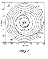
- the present planar array design 15 shown in Fig. 1 shows array elements 12 represented by circles. A subset of the elements 14 are highlighted to emphasize their distribution along a logarithmic spiral 16 .
- the highlighted elements 14 may be located along the spiral according to any of a number of methods.
- One preferred method, as shown in Fig. 1, is equi-annular area sampling where the M-1 outermost elements of the M-element spiral are located coincident with the geometric radial centers of concentric equal-area annuli.
- the Mth element is located independently at some radius less than that of the innermost of the aforementioned M-1 elements to enhance the performance of the array at the highest frequencies for its intended use.
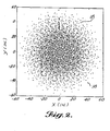
- Circular symmetry is achieved by clocking N-element circular arrays of equally spaced elements 17 off of each of the spiral elements 14 as shown in Fig. 1. If the number of elements in the circular arrays is odd, the resulting array has zero redundancy in its spatial sampling space. This is represented by the coarray shown in Fig. 2 which represents the set of all vector spacings between elements 12 in the array aperture of Fig. 1. Each point 18 in the coarray represents a vector difference between the locations of two elements in the array. For the present planar array design 15 , none of these vector differences is repeated.
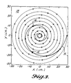
- FIG. 3 Alternative spiral element spacing methods are shown in Figs. 3 and 4.
- the spiral elements 14 are spaced on equal radial increments along the spiral 16 between an inner and outer radial specification.
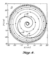
- Fig. 4 the spiral elements 14 are spaced in logarithmically increasing radial increments along the spiral 16 between an outer and inner radial specification (i.e., the radial increment between spiral elements increases as the spiral is traversed from the outermost to the innermost element). This is referred to as logarithmic radial spacing outside-in.
- Another method referred to as logarithmic radial spacing inside-out locates the spiral elements on logarithmically increasing radial increments along the spiral between an inner and outer radial specification.
- spiral element spacing methods exhibit trade-offs between array mainlobe width (i.e., array resolution) and sidelobe levels.
- arrays with the elements concentrated near the perimeter such as the array 18 of Fig. 3 have a narrower mainlobe and correspondingly higher average sidelobe levels.
- Arrays with the elements concentrated near the center such as the array 19 of Fig. 4 have a broader mainlobe and correspondingly lower average sidelobe levels.
- the embodiments of Figs. 1, 3, and 4 and the embodiment comprising logarithmic radial spacing inside-out are exemplary only of radial spacing configurations in accordance with the invention.
- the general design parameters for the present arrays are as follows: (1) logarithmic spiral angle; (2) inner radius; (3) outer radius; (4) number of elements per spiral; (5) number of elements per circle (i.e., number of spirals); and (6) spiral element spacing method. These parameters form a broad class of circularly symmetric non-redundant planar arrays (provided the number of elements per circle is odd) that have exceptionally low worst-case sidelobe characteristics across a broad range of frequencies compared to what can be achieved with regular or random arrays.
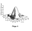
- Array patterns for the embodiment of Fig. 1 are shown for 1 kHz in Fig. 5, for 5 kHz in Fig. 6, and for 10 kHz in Fig. 7, with the array focused at a point 54 in. off broadside demonstrating the absence of grating lobes over a broad frequency range and broad scan region, and showing the circularly symmetric characteristics of the array.
- These exemplary array patterns were determined for frequencies corresponding to atmospheric propagation of acoustic waves using a propagation speed of 1125 ft./s.
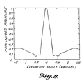
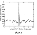
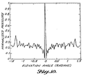
- Worst-case sidelobe characteristics for the embodiment of Fig. 1 are shown for 1 kHz in Fig. 8, for 5 kHz in Fig. 9, and for 10 kHz in Fig.
- Figs. 8, 9, and 10 show the array pattern envelope that is formed by taking the largest value from 45 azimuthal angle cuts through the array pattern at each of 91 elevation angles.
- Fig. 11 shows a block diagram for the instrumentation, signal conditioning, data acquisition, signal processing, and display system for an acoustic application of the array of Fig. 1.
- the N-channel array design 1 is implemented by positioning N microphones at appropriate spatial locations such that the positions of the centers of the microphone diaphragms relative to each other match the array design specification (i.e., the spatial coordinates).
- the N microphone systems consisting of microphone button (array element) 12 , pre-amplifier 3 , and transmission line 4 are fed into N corresponding input modules 5 .
- Each input channel contains programmable gain 6 , analog anti-alias filter 7 , and sample and hold analog-to-digital conversion 8 .
- Input channels share a common trigger bus 9 so that sample and hold is simultaneous.
- a common system bus 10 hosts the input modules and channels the simultaneously acquired time series data to the beamformer 11 .
- the beamformer may be one or more of a number of conventional time and/or frequency domain beamforming processes which provide data for readout means comprising a graphical display device 13.
- a frequency domain beamformer 11 provides signal processing from the planar array of N microphone elements 12 and 14 of Figs. 1 and 11 performing the following steps:
- the graphical device 13 then presents a contour plot of the estimated source distribution.
Landscapes
- Physics & Mathematics (AREA)
- Engineering & Computer Science (AREA)
- Acoustics & Sound (AREA)
- Health & Medical Sciences (AREA)
- Otolaryngology (AREA)
- Multimedia (AREA)
- Signal Processing (AREA)
- Measurement Of Velocity Or Position Using Acoustic Or Ultrasonic Waves (AREA)
- Circuit For Audible Band Transducer (AREA)
- Variable-Direction Aerials And Aerial Arrays (AREA)
- Radar Systems Or Details Thereof (AREA)
Claims (10)
- Kreissymmetrisches, nicht-redundantes ebenes Feld (15, 18, 19) für einen breiten Frequenzbereich, umfassend eine Vielzahl von Elementen (12), welche entlang einer Familie von identischen logarithmischen Spiralen (16) beabstandet angeordnet sind, wobei die Elemente (12) mit unterschiedlichen Radien von dem Ursprungspunkt der Spiralen beabstandet sind, wobei Mitglieder der Familie winkelmäßig gleichmäßig um den Ursprungspunkt herum beabstandet angeordnet sind und eine ungerade Anzahl an Mitgliedern in der Familie von Spiralen (16) vorhanden ist.
- Ebenes Feld (15, 18, 19) nach Anspruch 1 in Kombination mit Mitteln zum Empfangen von Signalenergie von jedem der Feldelemente (12) über separate Empfangspfade.
- Kombination nach Anspruch 2, kombiniert mit Mitteln, welche mit jedem der Empfangspfade gekoppelt sind, zum Verarbeiten der Signalenergie, um die Phase und Amplitude der Feldelemente (12) und dadurch den Hauptstrahl des Felds zu steuern.
- Ebenes Feld nach Anspruch 1, 2 oder 3 in Kombination mit Mitteln zum Zuführen von Signalenergie zu jedem der Feldelemente über separate Übertragungspfade.
- Kombination nach Anspruch 4, kombiniert mit Mitteln, welche mit jedem der Übertragungspfade gekoppelt sind, zur Verarbeitung der Signalenergie, um die Phase und die Amplitude der Feldelemente und dadurch den Hauptstrahl des Felds zu steuern.
- Kombinationen nach Anspruch 3 und 5, wobei die Elemente (12) des Felds (15) entlang jeder der logarithmischen Spiralen (16) auf konzentrischen Kreisen, welche die geometrischen radialen Mittelpunkte von Kreisringen gleicher Fläche bilden, sowie auf einem innersten konzentrischen Kreis, dessen Radius unabhängig festgelegt ist, angeordnet sind.
- Kombination nach Anspruch 3 und 5, wobei die Elemente des Felds (18) entlang jeder logarithmischen Spirale zwischen einem festgelegten inneren Radius und einem festgelegten äußeren Radius an gleichen radialen Inkrementen angeordnet sind.
- Kombination nach Anspruch 3 und 5, wobei die Elemente des Felds (19) entlang jeder logarithmischen Spirale (16) zwischen einem festgelegten äußeren Radius und einem festgelegten inneren Radius an logarithmisch zunehmenden radialen Inkrementen derart angeordnet sind, dass das radiale Inkrement zwischen den Elementen entlang der logarithmischen Spirale von dem äußersten Element zu dem innersten Element hin zunimmt.
- Kombination nach Anspruch 3 und 5, wobei die Elemente des Felds (19) entlang jeder logarithmischen Spirale zwischen einem festgelegten inneren Radius und einem festgelegten äußeren Radius an logarithmisch zunehmenden radialen Inkrementen derart angeordnet sind, dass das radiale Inkrement zwischen den Elementen entlang der logarithmischen Spirale von dem innersten Element zu dem äußersten Element hin zunimmt.
- Kombination nach einem der Ansprüche 5 - 9, wobei die Feldelemente passive akustische Sensoren (z.B. Kondensatormikrophone) sind und wobei die Mittel zum Empfangen und Verarbeiten der Signalenergie zur Steuerung der Phasenamplitude der Feldelemente ein N-Kanal-Signalaufbereitungssystem, welches einen Vorverstärker, eine Übertragungsleitung und Eingangsmodule mit einer Signalaufbereitungs- und Abtast-und-Halte-Analog/Digitalwandlungsfähigkeit für jeden Kanal umfasst, wobei sämtliche Eingangsmodule mit einem gemeinsamen Systembus gekoppelt sind, welcher an ein Datenverarbeitungssystem zur Strahlbündelung und daraus resultierend zur Erzeugung einer Abbildung der Geräuschquelle in Form einer Konturwiedergabe angeschlossen ist.
Applications Claiming Priority (2)
| Application Number | Priority Date | Filing Date | Title |
|---|---|---|---|
| US652629 | 1996-05-17 | ||
| US08/652,629 US6205224B1 (en) | 1996-05-17 | 1996-05-17 | Circularly symmetric, zero redundancy, planar array having broad frequency range applications |
Publications (2)
| Publication Number | Publication Date |
|---|---|
| EP0807990A1 EP0807990A1 (de) | 1997-11-19 |
| EP0807990B1 true EP0807990B1 (de) | 2001-06-27 |
Family
ID=24617538
Family Applications (1)
| Application Number | Title | Priority Date | Filing Date |
|---|---|---|---|
| EP97201405A Expired - Lifetime EP0807990B1 (de) | 1996-05-17 | 1997-05-09 | Redundanzlose kreissymmetrische ebene Gruppenantenne |
Country Status (7)
| Country | Link |
|---|---|
| US (1) | US6205224B1 (de) |
| EP (1) | EP0807990B1 (de) |
| JP (1) | JP3866828B2 (de) |
| KR (1) | KR100454669B1 (de) |
| CN (1) | CN1108529C (de) |
| CA (1) | CA2204298C (de) |
| DE (1) | DE69705357T2 (de) |
Cited By (1)
| Publication number | Priority date | Publication date | Assignee | Title |
|---|---|---|---|---|
| EP2315312A1 (de) | 2009-10-22 | 2011-04-27 | Toyota Motor Europe NV | Antenne mit schwach besetzter Gruppe von Elementen |
Families Citing this family (70)
| Publication number | Priority date | Publication date | Assignee | Title |
|---|---|---|---|---|
| GB9506725D0 (en) | 1995-03-31 | 1995-05-24 | Hooley Anthony | Improvements in or relating to loudspeakers |
| ATE376892T1 (de) | 1999-09-29 | 2007-11-15 | 1 Ltd | Verfahren und vorrichtung zur ausrichtung von schall mit einer gruppe von emissionswandlern |
| US6433754B1 (en) * | 2000-06-20 | 2002-08-13 | Northrop Grumman Corporation | Phased array including a logarithmic spiral lattice of uniformly spaced radiating and receiving elements |
| WO2002069448A1 (fr) * | 2001-02-26 | 2002-09-06 | Mitsubishi Denki Kabushiki Kaisha | Systeme d'antennes |
| JP3923431B2 (ja) * | 2001-02-27 | 2007-05-30 | 三菱電機株式会社 | アンテナ装置 |
| JP4445705B2 (ja) | 2001-03-27 | 2010-04-07 | 1...リミテッド | 音場を作り出す方法および装置 |
| US6842157B2 (en) * | 2001-07-23 | 2005-01-11 | Harris Corporation | Antenna arrays formed of spiral sub-array lattices |
| US6897829B2 (en) * | 2001-07-23 | 2005-05-24 | Harris Corporation | Phased array antenna providing gradual changes in beam steering and beam reconfiguration and related methods |
| US6670931B2 (en) | 2001-11-19 | 2003-12-30 | The Boeing Company | Antenna having cross polarization improvement using rotated antenna elements |
| US6606056B2 (en) | 2001-11-19 | 2003-08-12 | The Boeing Company | Beam steering controller for a curved surface phased array antenna |
| US20030125959A1 (en) * | 2001-12-31 | 2003-07-03 | Palmquist Robert D. | Translation device with planar microphone array |
| US6583768B1 (en) | 2002-01-18 | 2003-06-24 | The Boeing Company | Multi-arm elliptic logarithmic spiral arrays having broadband and off-axis application |
| US6781560B2 (en) | 2002-01-30 | 2004-08-24 | Harris Corporation | Phased array antenna including archimedean spiral element array and related methods |
| DK174558B1 (da) * | 2002-03-15 | 2003-06-02 | Bruel & Kjaer Sound & Vibratio | Stråleformende transducer-antennesystem |
| US6646621B1 (en) | 2002-04-25 | 2003-11-11 | Harris Corporation | Spiral wound, series fed, array antenna |
| DE10321986B4 (de) * | 2003-05-15 | 2005-07-14 | Fraunhofer-Gesellschaft zur Förderung der angewandten Forschung e.V. | Vorrichtung und Verfahren zum Pegel-Korrigieren in einem Wellenfeldsynthesesystem |
| GB0315426D0 (en) * | 2003-07-01 | 2003-08-06 | Mitel Networks Corp | Microphone array with physical beamforming using omnidirectional microphones |
| US7207942B2 (en) * | 2003-07-25 | 2007-04-24 | Siemens Medical Solutions Usa, Inc. | Adaptive grating lobe suppression in ultrasound imaging |
| US7599672B2 (en) * | 2003-07-29 | 2009-10-06 | National Institute Of Information And Communications Technology | Millimeter-wave-band radio communication method in which both a modulated signal and an unmodulated carrier are transmitted to a system with a receiver having plural receiving circuits |
| GB0420240D0 (en) * | 2004-09-13 | 2004-10-13 | 1 Ltd | Quasi-rectangular frame array antennae |
| US7420561B2 (en) * | 2005-07-01 | 2008-09-02 | Honeywell International Inc. | Diagnostic visual tools and methods for graphical comparison of data point and historical data density |
| GB2438259B (en) * | 2006-05-15 | 2008-04-23 | Roke Manor Research | An audio recording system |
| US7395180B2 (en) * | 2006-05-17 | 2008-07-01 | Lockheed Martin Corporation | Efficient translation of data from a two-dimensional array to a wedge |
| FR2923612B1 (fr) * | 2007-11-12 | 2011-05-06 | Super Sonic Imagine | Dispositif d'insonification comprenant un reseau tridimensionnel d'emetteurs disposes en spirale apte a generer un faisceau d'ondes focalisees de grande intensite |
| US8009507B2 (en) * | 2009-01-09 | 2011-08-30 | The Boeing Company | System and method for adaptable aperture planar phased array |
| US9191741B1 (en) | 2009-08-05 | 2015-11-17 | The Boeing Company | Variable aperture phased array |
| US8106849B2 (en) * | 2009-08-28 | 2012-01-31 | SVR Inventions, Inc. | Planar antenna array and article of manufacture using same |
| CN101860776B (zh) * | 2010-05-07 | 2013-08-21 | 中国科学院声学研究所 | 一种平面螺旋形传声器阵列 |
| IT1400033B1 (it) * | 2010-05-07 | 2013-05-17 | Mulargia | Antenna sismica a campionamento spaziale uniforme in lunghezza d'onda. |
| US8594735B2 (en) * | 2011-01-05 | 2013-11-26 | Alcatel Lucent | Conformal antenna array |
| CN102662170B (zh) * | 2012-04-27 | 2014-02-19 | 中国人民解放军国防科学技术大学 | 毫米波全息成像圆面错位线阵 |
| KR101213539B1 (ko) * | 2012-09-03 | 2012-12-18 | (주)에스엠인스트루먼트 | 멤스 마이크로폰 어레이를 이용한 음향감지 장치 및 음향카메라 |
| EP3012650B1 (de) * | 2013-06-21 | 2021-06-09 | SM Instruments Co., Ltd. | Mobiler schallquellenverfolgungssensor und herstellungsverfahren |
| JP6171752B2 (ja) * | 2013-09-06 | 2017-08-02 | 株式会社デンソー | 騒音軽減装置 |
| US9213078B1 (en) | 2014-05-31 | 2015-12-15 | The Boeing Company | Noise source decomposition system and method using an adaptable aperture phased array |
| JP2016008940A (ja) * | 2014-06-26 | 2016-01-18 | 株式会社デンソー | 位置情報提供装置、位置報知装置およびプログラム |
| US9612310B2 (en) | 2015-01-23 | 2017-04-04 | The Boeing Company | Method and apparatus for determining the direction of arrival of a sonic boom |
| US9554207B2 (en) | 2015-04-30 | 2017-01-24 | Shure Acquisition Holdings, Inc. | Offset cartridge microphones |
| US9565493B2 (en) | 2015-04-30 | 2017-02-07 | Shure Acquisition Holdings, Inc. | Array microphone system and method of assembling the same |
| US10367948B2 (en) | 2017-01-13 | 2019-07-30 | Shure Acquisition Holdings, Inc. | Post-mixing acoustic echo cancellation systems and methods |
| EP3425925A1 (de) * | 2017-07-07 | 2019-01-09 | Harman Becker Automotive Systems GmbH | Lautsprecherraumsystem |
| DE102017214575A1 (de) * | 2017-08-21 | 2019-02-21 | Astyx Gmbh | Abbildendes Radarsystem mit einem Empfangsarray zur Winkelbestimmung von Objekten in zwei Dimensionen durch eine gespreizte Anordnung der Empfangsantennen einer Dimension |
| JPWO2019167671A1 (ja) | 2018-03-02 | 2021-03-04 | ソニー株式会社 | マイクロホンアレイ、収録装置および方法、並びにプログラム |
| EP3804356A1 (de) | 2018-06-01 | 2021-04-14 | Shure Acquisition Holdings, Inc. | Musterbildende mikrofonanordnung |
| US11297423B2 (en) | 2018-06-15 | 2022-04-05 | Shure Acquisition Holdings, Inc. | Endfire linear array microphone |
| US11310596B2 (en) | 2018-09-20 | 2022-04-19 | Shure Acquisition Holdings, Inc. | Adjustable lobe shape for array microphones |
| CN109356576B (zh) * | 2018-10-23 | 2022-05-03 | 中国石油化工股份有限公司 | 测量平面径向流驱替压力梯度的物模实验装置 |
| JP7572964B2 (ja) | 2019-03-21 | 2024-10-24 | シュアー アクイジッション ホールディングス インコーポレイテッド | 阻止機能を伴うビーム形成マイクロフォンローブの自動集束、領域内自動集束、および自動配置 |
| WO2020191354A1 (en) | 2019-03-21 | 2020-09-24 | Shure Acquisition Holdings, Inc. | Housings and associated design features for ceiling array microphones |
| US11558693B2 (en) | 2019-03-21 | 2023-01-17 | Shure Acquisition Holdings, Inc. | Auto focus, auto focus within regions, and auto placement of beamformed microphone lobes with inhibition and voice activity detection functionality |
| US11445294B2 (en) | 2019-05-23 | 2022-09-13 | Shure Acquisition Holdings, Inc. | Steerable speaker array, system, and method for the same |
| EP3977449B1 (de) | 2019-05-31 | 2024-12-11 | Shure Acquisition Holdings, Inc. | Mit sprach- und rauschaktivitätsdetektion integrierter automatischer mischer mit niedriger latenz |
| JP7392969B2 (ja) * | 2019-08-19 | 2023-12-06 | 株式会社オーディオテクニカ | マイクロホン位置決定方法 |
| WO2021041275A1 (en) | 2019-08-23 | 2021-03-04 | Shore Acquisition Holdings, Inc. | Two-dimensional microphone array with improved directivity |
| USD943558S1 (en) | 2019-11-01 | 2022-02-15 | Shure Acquisition Holdings, Inc. | Housing for ceiling array microphone |
| USD943559S1 (en) | 2019-11-01 | 2022-02-15 | Shure Acquisition Holdings, Inc. | Housing for ceiling array microphone |
| US12028678B2 (en) | 2019-11-01 | 2024-07-02 | Shure Acquisition Holdings, Inc. | Proximity microphone |
| US11552611B2 (en) | 2020-02-07 | 2023-01-10 | Shure Acquisition Holdings, Inc. | System and method for automatic adjustment of reference gain |
| USD943552S1 (en) | 2020-05-05 | 2022-02-15 | Shure Acquisition Holdings, Inc. | Audio device |
| USD944776S1 (en) | 2020-05-05 | 2022-03-01 | Shure Acquisition Holdings, Inc. | Audio device |
| CN111543348B (zh) * | 2020-05-14 | 2022-03-18 | 深聆科技(北京)有限公司 | 养殖场的声音定位装置、方法及幼崽监控方法 |
| WO2021243368A2 (en) | 2020-05-29 | 2021-12-02 | Shure Acquisition Holdings, Inc. | Transducer steering and configuration systems and methods using a local positioning system |
| US11785380B2 (en) | 2021-01-28 | 2023-10-10 | Shure Acquisition Holdings, Inc. | Hybrid audio beamforming system |
| US12452584B2 (en) | 2021-01-29 | 2025-10-21 | Shure Acquisition Holdings, Inc. | Scalable conferencing systems and methods |
| US11671751B2 (en) | 2021-04-28 | 2023-06-06 | Sennheiser Electronic Gmbh & Co. Kg | Microphone array |
| EP4413745A1 (de) | 2021-10-04 | 2024-08-14 | Shure Acquisition Holdings, Inc. | Vernetzte automischersysteme und verfahren |
| EP4427465A1 (de) | 2021-11-05 | 2024-09-11 | Shure Acquisition Holdings, Inc. | Verteilter algorithmus zur automatischen mischung von sprache über drahtlose netzwerke |
| WO2023133513A1 (en) | 2022-01-07 | 2023-07-13 | Shure Acquisition Holdings, Inc. | Audio beamforming with nulling control system and methods |
| TWI837638B (zh) * | 2022-04-08 | 2024-04-01 | 圓展科技股份有限公司 | 收音裝置及音訊處理方法 |
| CN115047402B (zh) * | 2022-04-25 | 2025-04-15 | 同济大学 | 一种基于波束成形的bf-sage高精度参数估计算法 |
Family Cites Families (25)
| Publication number | Priority date | Publication date | Assignee | Title |
|---|---|---|---|---|
| US3524188A (en) | 1967-08-24 | 1970-08-11 | Rca Corp | Antenna arrays with elements aperiodically arranged to reduce grating lobes |
| US3811129A (en) | 1972-10-24 | 1974-05-14 | Martin Marietta Corp | Antenna array for grating lobe and sidelobe suppression |
| JPS5759682B2 (de) * | 1975-02-26 | 1982-12-16 | Mitsubishi Electric Corp | |
| US3969732A (en) * | 1975-04-24 | 1976-07-13 | Holloway Albert L | Spiral antenna circuit |
| US4060792A (en) * | 1976-06-17 | 1977-11-29 | Raytheon Company | Hard clipped beam former |
| US4169257A (en) * | 1978-04-28 | 1979-09-25 | The United States Of America As Represented By The Secretary Of The Navy | Controlling the directivity of a circular array of acoustic sensors |
| US4243993A (en) * | 1979-11-13 | 1981-01-06 | The Boeing Company | Broadband center-fed spiral antenna |
| US4324140A (en) * | 1980-07-31 | 1982-04-13 | The United States Of America As Represented By The Secretary Of The Navy | Electronically simulated rotating prism for ultrasonic beam scanning |
| US4363115A (en) * | 1981-01-26 | 1982-12-07 | The United States Of America As Represented By The Secretary Of The Navy | Low frequency, log-periodic acoustic array |
| US4420825A (en) * | 1981-05-15 | 1983-12-13 | Sanders Associates, Inc. | Element-sited beamformer |
| US4525816A (en) * | 1981-09-25 | 1985-06-25 | The Marconi Company Limited | Sonar arrangements |
| US4525720A (en) * | 1982-10-15 | 1985-06-25 | The United States Of America As Represented By The Secretary Of The Navy | Integrated spiral antenna and printed circuit balun |
| US4559605A (en) * | 1983-09-16 | 1985-12-17 | The Boeing Company | Method and apparatus for random array beamforming |
| US4905011A (en) | 1987-07-20 | 1990-02-27 | E-Systems, Inc. | Concentric ring antenna |
| JP3018353B2 (ja) * | 1989-08-10 | 2000-03-13 | 凸版印刷株式会社 | ラジアルラインスロットアンテナ |
| JPH03219706A (ja) * | 1989-11-30 | 1991-09-27 | Rajiaru Antenna Kenkyusho:Kk | 平面アンテナ |
| US5151705A (en) | 1991-02-15 | 1992-09-29 | Boeing Aerospace And Electronics | System and method of shaping an antenna radiation pattern |
| JPH05129831A (ja) * | 1991-04-02 | 1993-05-25 | Arimura Giken Kk | 表面波線路アレーアンテナ |
| JP3126043B2 (ja) * | 1991-08-23 | 2001-01-22 | カヤバ工業株式会社 | 可変容量型センサの製造方法 |
| JPH0575331A (ja) * | 1991-09-17 | 1993-03-26 | Denki Kogyo Co Ltd | 平面アンテナ |
| JPH0591588A (ja) * | 1991-09-27 | 1993-04-09 | Railway Technical Res Inst | 指向方向可変指向性収音装置 |
| JP2821960B2 (ja) * | 1991-10-08 | 1998-11-05 | 富士通株式会社 | 映像伝送装置の監視回路 |
| CA2121153A1 (en) * | 1993-04-19 | 1994-10-20 | John C. Conrad | Active antenna array |
| FR2712121B1 (fr) * | 1993-11-02 | 1995-12-15 | Thomson Csf | Antenne à réseau d'éléments rayonnants. |
| US5838284A (en) * | 1996-05-17 | 1998-11-17 | The Boeing Company | Spiral-shaped array for broadband imaging |
-
1996
- 1996-05-17 US US08/652,629 patent/US6205224B1/en not_active Expired - Lifetime
-
1997
- 1997-05-02 CA CA002204298A patent/CA2204298C/en not_active Expired - Lifetime
- 1997-05-09 EP EP97201405A patent/EP0807990B1/de not_active Expired - Lifetime
- 1997-05-09 DE DE69705357T patent/DE69705357T2/de not_active Expired - Lifetime
- 1997-05-09 CN CN97111512A patent/CN1108529C/zh not_active Expired - Lifetime
- 1997-05-15 JP JP12538297A patent/JP3866828B2/ja not_active Expired - Lifetime
- 1997-05-17 KR KR1019970019162A patent/KR100454669B1/ko not_active Expired - Lifetime
Cited By (2)
| Publication number | Priority date | Publication date | Assignee | Title |
|---|---|---|---|---|
| EP2315312A1 (de) | 2009-10-22 | 2011-04-27 | Toyota Motor Europe NV | Antenne mit schwach besetzter Gruppe von Elementen |
| WO2011048195A1 (en) | 2009-10-22 | 2011-04-28 | Toyota Motor Europe Nv/Sa | Antenna having sparsely populated array of elements |
Also Published As
| Publication number | Publication date |
|---|---|
| CN1169540A (zh) | 1998-01-07 |
| KR970077824A (ko) | 1997-12-12 |
| EP0807990A1 (de) | 1997-11-19 |
| JPH1093335A (ja) | 1998-04-10 |
| CA2204298A1 (en) | 1997-11-17 |
| KR100454669B1 (ko) | 2004-12-29 |
| CN1108529C (zh) | 2003-05-14 |
| CA2204298C (en) | 2004-03-16 |
| JP3866828B2 (ja) | 2007-01-10 |
| US6205224B1 (en) | 2001-03-20 |
| DE69705357D1 (de) | 2001-08-02 |
| DE69705357T2 (de) | 2001-10-11 |
Similar Documents
| Publication | Publication Date | Title |
|---|---|---|
| EP0807990B1 (de) | Redundanzlose kreissymmetrische ebene Gruppenantenne | |
| US5838284A (en) | Spiral-shaped array for broadband imaging | |
| EP1485968B1 (de) | Strahlformungs-wandlerarray | |
| CN113866709A (zh) | 一种相控阵列交叉多波束比幅测向方法 | |
| US20250158694A1 (en) | Wideband Beamforming with Main Lobe Steering and Interference Cancellation at Multiple Independent Frequencies and Spatial Locations | |
| CN112083432A (zh) | 基于声学轨道角动量的超精细三维成像方法 | |
| Hald et al. | A class of optimal broadband phased array geometries designed for easy construction | |
| US6778148B1 (en) | Sensor array for enhanced directivity | |
| US5596550A (en) | Low cost shading for wide sonar beams | |
| EP0796487B1 (de) | Gerichtete wandleranordnung mit hoher verstärkung | |
| CN111366918A (zh) | 一种切旁瓣方法及装置 | |
| JP7447513B2 (ja) | ソーナー装置と目標方位算出方法及びプログラム | |
| US4591864A (en) | Frequency independent twisted wave front constant beamwidth lens antenna | |
| RU2178572C2 (ru) | Приемная антенна гидроакустической станции кругового обзора | |
| CN117223295A (zh) | 麦克风阵列 | |
| Chitre et al. | Optimisation and beamforming of a two dimensional sparse array | |
| Cerwin et al. | The VLAA: a very large acoustic array | |
| JP2007243352A (ja) | アレーアンテナ装置 | |
| Lardies et al. | A very wide bandwidth constant beamwidth acoustical end-fire line array without side lobes | |
| Suleiman et al. | Acoustic Tracking System Based on Microphones Array Technique | |
| James | Frequency Independent | |
| Tian et al. | Broadband Beam Forming for Circular Sensor Array via Modal Decomposition |
Legal Events
| Date | Code | Title | Description |
|---|---|---|---|
| PUAI | Public reference made under article 153(3) epc to a published international application that has entered the european phase |
Free format text: ORIGINAL CODE: 0009012 |
|
| AK | Designated contracting states |
Kind code of ref document: A1 Designated state(s): DE FR GB |
|
| 17P | Request for examination filed |
Effective date: 19980429 |
|
| 17Q | First examination report despatched |
Effective date: 19990407 |
|
| GRAG | Despatch of communication of intention to grant |
Free format text: ORIGINAL CODE: EPIDOS AGRA |
|
| GRAG | Despatch of communication of intention to grant |
Free format text: ORIGINAL CODE: EPIDOS AGRA |
|
| GRAH | Despatch of communication of intention to grant a patent |
Free format text: ORIGINAL CODE: EPIDOS IGRA |
|
| GRAH | Despatch of communication of intention to grant a patent |
Free format text: ORIGINAL CODE: EPIDOS IGRA |
|
| GRAA | (expected) grant |
Free format text: ORIGINAL CODE: 0009210 |
|
| AK | Designated contracting states |
Kind code of ref document: B1 Designated state(s): DE FR GB |
|
| REF | Corresponds to: |
Ref document number: 69705357 Country of ref document: DE Date of ref document: 20010802 |
|
| ET | Fr: translation filed | ||
| REG | Reference to a national code |
Ref country code: GB Ref legal event code: IF02 |
|
| PLBE | No opposition filed within time limit |
Free format text: ORIGINAL CODE: 0009261 |
|
| STAA | Information on the status of an ep patent application or granted ep patent |
Free format text: STATUS: NO OPPOSITION FILED WITHIN TIME LIMIT |
|
| 26N | No opposition filed | ||
| REG | Reference to a national code |
Ref country code: FR Ref legal event code: PLFP Year of fee payment: 20 |
|
| PGFP | Annual fee paid to national office [announced via postgrant information from national office to epo] |
Ref country code: GB Payment date: 20160527 Year of fee payment: 20 Ref country code: DE Payment date: 20160527 Year of fee payment: 20 |
|
| PGFP | Annual fee paid to national office [announced via postgrant information from national office to epo] |
Ref country code: FR Payment date: 20160530 Year of fee payment: 20 |
|
| REG | Reference to a national code |
Ref country code: DE Ref legal event code: R071 Ref document number: 69705357 Country of ref document: DE |
|
| REG | Reference to a national code |
Ref country code: GB Ref legal event code: PE20 Expiry date: 20170508 |
|
| PG25 | Lapsed in a contracting state [announced via postgrant information from national office to epo] |
Ref country code: GB Free format text: LAPSE BECAUSE OF EXPIRATION OF PROTECTION Effective date: 20170508 |