EP0807840A2 - Mikroskopsystem - Google Patents
Mikroskopsystem Download PDFInfo
- Publication number
- EP0807840A2 EP0807840A2 EP97107790A EP97107790A EP0807840A2 EP 0807840 A2 EP0807840 A2 EP 0807840A2 EP 97107790 A EP97107790 A EP 97107790A EP 97107790 A EP97107790 A EP 97107790A EP 0807840 A2 EP0807840 A2 EP 0807840A2
- Authority
- EP
- European Patent Office
- Prior art keywords
- lens
- objective lens
- objective
- microscope system
- sample
- Prior art date
- Legal status (The legal status is an assumption and is not a legal conclusion. Google has not performed a legal analysis and makes no representation as to the accuracy of the status listed.)
- Withdrawn
Links
Images


Classifications
-
- G—PHYSICS
- G02—OPTICS
- G02B—OPTICAL ELEMENTS, SYSTEMS OR APPARATUS
- G02B21/00—Microscopes
- G02B21/02—Objectives
Definitions
- the present invention relates to a microscope system for observing a microstructure, such as a micro-organism or a cell, with desired magnifications.
- a microscope system including an objective lens and a focusing lens and referred to as an "infinity system” includes a microscope device in which a parallel ray portion is formed within a space between the objective lens and the focusing lens.
- a focal length of the focusing lens is set from 160 mm to 250 mm in view of the total size of the microscope and ease of aberration correction.
- a distance between a sample surface and an attachment plane of the objective lens i.e ., a parfocal length, is set at 45 mm.
- a diameter of a screw formed on a portion by which the objective lens is attached to a microscope body or, in other words, an outer diameter of a screw formed on an attachment portion of the objective lens ranges from approximately 20 mm to 25 mm. This range is determined by the upper limitation on the size of a turret style magnification changer, referred to as a revolver, and the minimum limitation of a space for the parallel rays.
- the focal length of the focusing lens is set from 160 mm to 250 mm and the parfocal length of the objective lens is set at 45 mm.
- a combination of the above parameters provides a distance between an object surface (a sample surface) and an end plane of the objective lens of about 50 mm. Such a distance causes many disadvantages when a multi-level change in a magnification factor of the microscope is performed.
- a focal length of the focusing lens is set at 200 mm and a magnification factor of the objective lens, for an extremely low magnification, is set at 1.
- a telecentric ratio of the objective lens must be set to 0.25 in this example in order for the objective lens having a focal length of 200 mm to be placed in a space having a size of about 50 mm ( i.e ., a space between the sample surface and the end plane of the objective lens). This makes it impossible to realize an objective lens which has a general telecentric shape at the object side and in which aberration is corrected.
- the diameter of the screw on the attachment portion through which the objective lens is attached to the revolver ranges from 20 mm to 25 mm.
- a numerical aperture N.A.' at the image side of the objective lens (a "rear" numerical aperture) is set at 0.05.
- the focal length of the focusing lens be 200 mm
- a demand for an objective lens having a large rear numerical aperture N.A.' is therefore present.
- epi-fluorescence microscopy which requires much more light for gaining a bright image, it is especially important to have the rear numerical aperture N.A.' of the objective lens be as high as possible. This is because the image brightness is determined by the rear numerical aperture N.A.' power 2.
- a microscope system for observing an image of a sample at desired magnifications includes a first objective lens having an object side surface which has telecentric optics and a focusing lens, disposed on an optical path through which optical rays emitted from the first objective lens travel, for focusing the optical rays on the sample to form a sample image.
- a second objective lens has a magnification factor different from that of the first objective lens.
- An interchanging member, holding the first objective lens and the second objective lens, is used for selecting one of the first objective lens and the second objective lens and placing the selected objective lens on an observational optical path between the sample and the focusing lens.
- D is a parfocal length which equals a distance between the surface of the sample and an attachment plane of the objective lens and fI is a focal length of the focusing lens.
- ⁇ is an outer diameter of a screw portion of an attachment portion of the objective lens.
- the attachment portion is fitted to an interchanging member.
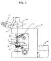
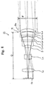
- Figure 1 is a schematic representation of an embodiment of a microscope in accordance with the present invention.
- Figure 2 is an enlarged view illustrating the main parts of the microscope shown in Figure 1.
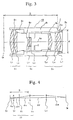
- Figure 3 is a cross-sectional view of an objective lens useable for an extremely low magnification.
- Figure 4 is a diagram illustrating an optical arrangement of the objective lens with an extremely low magnification shown in Figure 3.
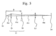
- Figure 5 is a diagram illustrating an optical arrangement of an objective lens with a high magnification.
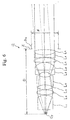
- Figure 6 is an optical path diagram for an objective lens having a magnification factor of 10.
- Figure 7 is a cross-sectional view of a focusing lens.
- Figure 8 is an optical path diagram for an objective lens with a magnification factor of 2.
- Figure 9 illustrates aberration diagrams for the objective lens with a magnification factor of 10.
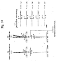
- Figure 10 illustrates aberration diagrams for the objective lens with a magnification factor of 2.
- the microscope system of the present invention includes an objective lens which has a telecentric surface facing a sample.
- the objective lens functions to collimate light from the sample into a collimated light beam or parallel rays.
- a focusing lens is provided for focusing the parallel rays from the objective lens to form an image of the sample.
- the microscope system is arranged to satisfy the following requirement or inequality (1): 0.29 ⁇ D/fI ⁇ 0.40 where D is a distance between an attachment plane of the objective lens and a surface of the sample, and fI is a focal length of the focusing lens.
- the size of the microscope is appropriate for a user to operate, and a lens with an extremely low magnification, e.g ., with a magnification factor of 1, can be used as the objective lens of the microscope system.
- a lens with an extremely low magnification e.g ., with a magnification factor of 1
- the requirement (1) set forth above defines an appropriate range for a ratio of the distance D between the attachment plane of the objective lens and the sample surface to the focal length fI of the focusing lens. If the ratio is smaller than the minimum limitation (i.e ., 0.29), since some design parameters are multiplied by a telecentric ratio so is to design an objective lens with an extremely low magnification factor, then it is difficult to realize a microscope objective lens which has a nearly telecentric surface at the object (sample) side and offers well-balanced correction for a variety of aberrations.
- the minimum limitation i.e . 0.29
- the ratio is larger than the maximum limitation (i.e ., 0.40)
- the objective lens itself becomes too large, so that ease of operation is degraded when a user rotates the revolver to select one of a plurality of objective lenses for the purpose of changing the magnification factor.
- the rotation of the revolver With respect to the rotation of the revolver, a space required for interchanging the objective lenses also becomes large. This is inconsistent with a demand for miniaturization.
- the following requirement is also preferably satisfied: 0.35 ⁇ ⁇ /D ⁇ 0.50
- ⁇ is an outer diameter of a screw portion (set screw) of an attachment portion of the objective lens.
- the requirement (2) defines an appropriate range of a ratio of the screw diameter ⁇ of the attachment portion to the distance D between the attachment plane of the objective lens and the sample surface. If the ratio is smaller than the minimum limitation (i.e ., 0.35), then it is impossible to place a lens with a large effective diameter at the position which is closest to the image side of an objective lens having a large rear numerical aperture.
- the ratio is larger than the maximum limitation (i.e ., 0.50)
- the outer diameter of the set screw becomes so large that it is difficult to attach many objective lenses to the revolver.
- the size of the revolver becomes too large to operate easily.
- the distance D between the attachment plane of the objective lens and the sample surface is set extremely small, then it is difficult to realize a microscope objective lens which has a nearly telecentric surface at the object (sample) side and yet offers well-balanced correction for a variety of aberrations.
- the focusing lens it is additionally preferable for the focusing lens to meet the following requirement: 190 mm ⁇ fI ⁇ 220 mm
- fI is smaller than the minimum limitation (i.e ., 190 mm), then an outer diameter of the focusing lens itself becomes large when securing a space between the objective lens and the focusing lens while obtaining a desired angle of view.
- the maximum limitation i.e ., 220 mm
- Figure 1 illustrates a microscope including a first objective lens 10 for an extremely low magnification, e.g ., having a magnification factor of 1, and a second objective lens 11 for a high magnification, e.g ., having a magnification factor of 40. Both of the lenses 10 and 11 are attached to a revolver 20.
- Figure 1 shows an arrangement in which the first objective lens 10 for an extremely low magnification is placed on an observational optical path.
- the revolver 20 is fitted to a barrel base (a microscope body) 21.
- the upper portion of the barrel base 21 is provided with a lens barrel 22.
- An ocular unit 23 including oculars for visually observing an image of a sample or specimen is attached to the lens barrel 22.
- a focusing lens LI for forming an image of a sample by focusing light passing through the objective lens (10 or 11), and a prism P and a mirror M for guiding the light passing through the focusing lens LI into the ocular unit 23.
- the barrel base 21 is provided with a stage for mounting a sample O and an illumination unit 40 for irradiating light toward the sample.
- the light from the illumination unit 40 is used to carry out a penetration type illumination of the sample O on the stage 30 through a condenser lens 41.
- Figure 1 illustrates an arrangement in which the first objective lens 10 for extremely low magnification is placed on the observational optical path.
- rotating the revolver 20 around an rotational axis 20Ax so as to place the second objective lens 11 for high magnification on the observational optical path makes it possible to observe the sample at a higher magnification factor.
- Figure 2 shows a structure of the revolver 20 to which objective lenses can be attached.
- the revolver 20 is rotatably supported by the barrel base 21 so as to allow the revolver 20 to rotate about the rotational axis 20Ax oriented at an angle relative to an optical axis Ax.
- the first objective lens 10 for an extremely low magnification includes lenses (O1, O2) having an ability to convert a light ray from the sample O to a parallel ray.
- the first objective lens 10 further includes a lens barrel B for holding the lenses (O1, O2).
- a male screw Ba with a diameter ⁇ of 25 mm is formed on the attachment portion at one end of the lens barrel B.
- the male screw on the attachment portion of the objective lens 10 and the female screws on the openings 20a of the revolver 20 are designed to allow the objective lens 10 to be screwed into the revolver 20.
- a portion of the objective lens 10 at the same level as the bottom of the openings 20a of the revolver 20 forms an attachment plane Z.
- a distance between the attachment plane Z and the sample surface (specimen surface or object surface) Op measured along an optical path of the objective lens 10 is parfocal length D.
- D 60 mm.
- the second objective lens 11 for a higher magnification as shown in Figure 1 can be attached to the revolver 20. Thereafter, the revolver 20 can be rotated around the rotational axis 20Ax so as to place the second objective lens 11 for a higher magnification in the observational optical path.
- the distance between the attachment plane Z and the sample surface (specimen surface) Op measured along an optical path of the lens 11, which is a parfocal length D of the lens 11, is set be equal to the parfocal length D of the lens 10, i.e ., 60 mm.
- the object or sample is kept nearly in focus by the microscope system even when the objective lenses are interchanged with each other by rotating the revolver 20.
- Figure 3 shows a specific example of the objective lens 10 for an extremely low magnification.
- the objective lens illustrated includes three lens groups. These lens groups include a first lens group G1 with a positive refractive power, a second lens group G2 with a negative refractive power, and a third lens group G3 with a positive refractive power arranged in order from the side of the sample surface Op.
- the first lens group G1 is made by two positive lenses (L1, L2).
- the second lens group G2 is made of a composite or cemented negative lens having a negative positive lens L3 and a positive lens L4.
- the third lens group G3 is made of a composite or cemented negative lens having a positive lens L5, a negative positive lens L6 and a positive lens L7.
- Each lens (L1 to L7) of the objective lens for an extremely low magnification is secured to one of several lens holders (B1 to B5).
- the lens holders (B1 to B5), together with a stop holder in which a stop S is integrated with its holder, are fitted in the lens barrel B.
- the following tables list optical data for the objective lens having a magnification factor of 1 and the focusing lens of Figure 3.
- the data are obtained by an optical arrangement as shown in Figure 4, in which the objective lens 10 collimates light from a sample into parallel rays and the parallel rays are focused on a prescribed position by the focusing lens L1.
- N.A. is an object side numerical aperture of the objective lens for an extremely low magnification.
- F is a focal length of the objective lens, in mm, for an extremely low magnification
- D is a parfocal length of the objective lens, in mm, for an extremely low magnification
- f1 is a focal length of the first lens group G1, in mm
- f2 is a focal length of the second lens group G2, in mm
- f3 is a focal length of the third lens group G3, in mm
- fI is a focal length of the focusing lens LI, in mm
- d01 is a distance between the sample surface (specimen surface or object surface) Op and a principal point of the first lens group G1, in mm
- d12 is a distance between a principal point of the first lens group G1 and a principal point of the second lens group G2, in mm
- d23 is a distance between a principal point of the second lens group G2 and a principal point of the third lens group G3, in mm
- d3I is a distance between a principal point
- a diameter of the observable field of view for the sample is set at 25 mm
- an object side effective diameter of the first lens group G1 is set at 25.5 mm
- an image side effective diameter of the third lens group G3 is set at 20 mm.
- a diameter of the observable field of view for the sample is set at 25 mm
- an object side effective diameter of the first lens group G1 is set at 25.5 mm
- an image side effective diameter of the third lens group G3 is set at 20 mm.
- Figure 5 illustrates an optical arrangement of the objective lens 11 having a magnification factor of 40 and the focusing lens LI which can be combined with an objective lens 10 with optical characteristics listed in Table 1 or Table 2.
- the objective lens 11 having a magnification factor of 40 includes two lens groups. These groups include a first lens group G1, with a positive refractive power, and a second lens group G2, with a negative refractive power.
- the groups G1 and G2 are arranged, in order, from the side of the sample surface Op.
- Each of the lens groups G1 and G2 is supported by a respective holder element (not shown) which is fitted in a lens barrel B (not shown).
- the lens barrel B of the objective lens 11 also has an attachment portion Ba at one of its ends.
- the following table lists optical data for the objective lens 11 having a magnification factor of 40 as shown in Figure 5.
- the data is obtained by an optical arrangement as shown in Figure 5, in which N.A. is an object side numerical aperture of the objective lens 11 for a high magnification, F is a focal length of the objective lens 11 for a high magnification, in mm, D is a parfocal length of the objective lens 11 for a high magnification, in mm, f1 is a focal length of the first lens group G1, in mm, f2 is a focal length of the second lens group G2, in mm, and fI is a focal length of the focusing lens LI, in mm, d01 is a distance between the sample surface (specimen surface or object surface) Op and a principal point of the first lens group G1, in mm, d12 is a distance between a principal point of the first lens group G1 and a principal point of the second lens group G2, in mm, d2I is a distance between
- an object side effective diameter of the first lens group G1 is 2.6 mm
- an image side effective diameter of the second lens group G2 is 11 mm.
- the parfocal length of the objective lens 10 with a magnification factor of 1 as characterized by Tables 1 and 2 and the parfocal length of the objective lens 11 with a magnification factor of 40 as characterized by Table 3 are both set at 60 mm.
- the diameters of all the attachment portions Ba of the lens barrels B from an extremely low magnification to a high magnification are set at 25 mm.
- the total magnification factor M of the microscope system in which the objective lens 10 of the first example or the second example is placed in the observational optical path via the revolver 20 is 10.
- the total magnification factor M of the microscope system in which the objective lens 11 of the third example is placed in the observational optical path via the revolver 20 is 400.
- an objective lens with a magnification factor of 1 and an objective lens with a magnification factor of 40 have been described as an example of the objective lens combination which can be attached to the revolver 20, any combination of a plurality of objective lenses, each having an arbitrary magnification factor, may be employed.
- a parfocal length D of each objective lens and a diameter ⁇ of an attachment portion Ba of each lens barrel are preferably set to be equal to each other.
- an objective lens with a magnification factor of 10 and an objective lens with a magnification factor of 2 will be described.
- a parfocal length D of each objective lens and a diameter ⁇ of an attachment portion Ba of each lens barrel are set equal to those of the objective lenses described above. Therefore, these objective lenses can be attached to the revolver 20 and be used in combination with the objective lens with a magnification factor of 1 and the objective lens with a magnification factor of 40 described above.
- Figure 6 shows an optical path diagram for an objective lens 12 with a magnification factor of 10.
- the objective lens 12 is arranged in this order from the side of the lens facing the sample Op.
- the objective lens includes, from a sample side, a meniscus positive lens L1 with a concave surface facing the sample, a bi-convex lens L2, a negative lens of a totally meniscus shape with a cemented bi-convex lens L3 and a bi-concave lens L4, a cemented negative lens of a totally meniscus shape, made by a bi-concave lens L5 and a bi-convex lens L6, a cemented negative lens of a totally meniscus shape, made by a bi-convex lens L7, a bi-concave lens L8 and a bi-convex lens L9.
- Each lens (L1 to L9) of the objective lens 12 is supported by a respective lens holder element (not shown) which is fitted in a lens barrel (not shown) similar to that shown in Figure 3.
- a lens barrel (not shown) similar to that shown in Figure 3.
- an attachment plane Z of the objective lens 12 and an attachment portion Ba are also shown.
- the objective lens 12 of Figure 6 is used for converting light from the sample Op into parallel rays.
- a focusing lens LI as shown in Figure 7 is disposed.
- Figure 7 shows the focusing lens LI as including a first lens group and a second lens group arranged in order from the light incoming side.
- the first lens group is a cemented positive lens of a totally meniscus shape having a bi-convex lens L10 and a bi-concave lens L11.
- the second lens group is a cemented negative lens of a totally meniscus shape having a bi-convex lens L12 and a bi-concave lens L13.
- a prism block P for deflecting the optical path is also shown in Figure 7.
- the following table lists lens data for the objective lens 12 having a magnification factor of 10 as shown in Figure 6, together with data for the a cover glass, the focusing lens LI of Figure 7 and the prism block P.
- N.A. is an objective side numerical aperture of the objective lens 12 with a magnification factor of 10
- F is a focal length of the objective lens 12
- D is a parfocal length of the objective lens 12
- r is a curvature of each lens surface, in mm
- d is a distance between the lens surfaces
- nd is a refractive index for d-line (587.6 nm)
- ⁇ d is an Abbe number for d-line (587.6 nm).
- the reference character fai designates an effective diameter of each lens surface, in mm.
- the left column indicates a lens surface number
- ⁇ indicates an outer diameter of the attachment portion Ba, in mm
- fI indicates a focal length of each lens (L10 to L13) in mm.
- Figure 8 is an optical path diagram for an objective lens with a magnification factor of 2.
- the objective lens 13 is arranged in order from the side of the sample Op.
- the objective has a bi-convex lens L1, a meniscus negative lens L2 which has a convex surface facing to the sample, a cemented negative lens of a totally meniscus shape and including a bi-concave lens L3, a bi-convex lens L4 and a meniscus positive lens L5 which has a concave surface facing the sample, a cemented positive lens of a totally meniscus shape including a bi-concave lens L6 and a bi-convex lens L7, and a meniscus positive lens L8 which has a concave surface facing the sample.
- each lens (L1 to L8) of the objective lens 13 is supported by a respective lens holder element (not shown) which is fitted in a lens barrel (not shown).
- a lens holder element not shown
- an attachment plane Z of the objective lens 13 and an attachment portion Ba are also shown.
- the objective lens 13 of Figure 8 is used for converting light from the sample Op into parallel rays.
- a focusing lens LI as shown in Figure 7 is disposed.
- Table 5 lists optical data for the objective lens 13 having a magnification factor of 2 as shown in Figure 8 together with data for a cover glass, the focusing lens LI of Figure 7, and the prism block P.
- N.A. is an object side numerical aperture of the objective lens 13 with a magnification factor of 2.
- F is a focal length of the objective lens 13, in mm
- D is a parfocal length of the objective lens 13, in mm.
- the reference character r is a curvature of each lens surface, in mm
- d is a distance between the lens surfaces, in mm.
- the reference character nd is a refractive index for d-line (587.6 nm)
- ⁇ d is an Abbe number for d-line (587.6 nm)
- fai is an effective diameter of each lens surface, in mm.
- Table 4 the left column indicates a lens surface number
- ⁇ indicates an outer diameter, in mm, of the attachment portion Ba
- fI indicates a focal length of each lens (L10 to L13) of the focusing lens in mm.
- Part (a) of Figure 9 is a spherical aberration diagram of the objective lens 12 with the parameters set forth in Table 4.
- Part (b) of Figure 9 is an astigmatism diagram of the objective lens 12 with the parameters set forth in Table 4.
- Part (c) of Figure 9 is a distortion diagram of the objective lens 12 with the parameters set forth in Table 4.
- Part (d) of Figure 9 is a lateral chromatic aberration diagram of the objective lens 12 with the parameters set forth in Table 4.
- Part (e) of Figure 9 is a coma (transverse aberration) diagram of the objective lens 12 with the parameters set forth in Table 4 at an image height of 12.5 mm.
- Part (f) of Figure 9 is a coma diagram of the objective lens 12 similar to part (e) but at an image height of 11.3 mm.
- Part (g) of Figure 9 is a coma diagram of the objective lens 12 similar to part (e) but at an image height of 8.8 mm.
- Part (h) of Figure 9 is a coma diagram of the objective lens 12 similar to part (e) but at an image height of 6.3 mm.
- part (i) of Figure 9 is a coma diagram of the objective lens 12 similar to part (e) but at an image height of 0.
- Part (a) of Figure 10 is a spherical aberration diagram of the objective lens 13 with the parameters set forth in Table 5.
- Part (b) of Figure 10 is an astigmatism diagram of the objective lens 13 with the parameters set forth in Table 5.
- Part (c) of Figure 10 is a distortion diagram of the objective lens 13 with the parameters set forth in Table 5.
- Part (d) of Figure 10 is a lateral chromatic aberration diagram of the objective lens 13 with the parameters set forth in Table 5.
- Part (e) of Figure 10 is a coma (transverse aberration) diagram of the objective lens 13 with the parameters set forth in Table 5 at an image height of 12.5 mm.
- Parts (f), (g), (h) and (i) of Figure 10 are coma diagrams of the objective lens 13 similar to part (e) but at image heights of 11.3 mm, 8.8 mm, 6.3 mm and 0 mm.
- NA designates an object side numerical aperture of the objective lens
- Y designates an image height in mm
- d designates d-line (587.6 nm)
- C designates a C-line (656.3 nm)
- F designates F-line (486.1 nm)
- g designates g-line (435.8 nm).
- broken lines indicate the meridional image plane and solid lines indicate the sagittal image plane.
- the objective lenses 12 and 13 offer an excellent image forming performance.
- the microscope system of the invention can use a plurality of objective lenses offering excellent image forming characteristics and having wide magnification ranges, i.e . from extremely low magnifications (with a magnification factor of 1) to high magnifications.
- the microscope is easily operated, and a sample can be observed over a wide magnification range.
Landscapes
- Physics & Mathematics (AREA)
- Chemical & Material Sciences (AREA)
- Analytical Chemistry (AREA)
- General Physics & Mathematics (AREA)
- Optics & Photonics (AREA)
- Lenses (AREA)
- Microscoopes, Condenser (AREA)
Applications Claiming Priority (4)
| Application Number | Priority Date | Filing Date | Title |
|---|---|---|---|
| JP11806096 | 1996-05-13 | ||
| JP118060/96 | 1996-05-13 | ||
| JP09064493A JP3123457B2 (ja) | 1996-05-13 | 1997-03-18 | 顕微鏡 |
| JP64493/97 | 1997-03-18 |
Publications (2)
| Publication Number | Publication Date |
|---|---|
| EP0807840A2 true EP0807840A2 (de) | 1997-11-19 |
| EP0807840A3 EP0807840A3 (de) | 1999-05-06 |
Family
ID=26405600
Family Applications (1)
| Application Number | Title | Priority Date | Filing Date |
|---|---|---|---|
| EP97107790A Withdrawn EP0807840A3 (de) | 1996-05-13 | 1997-05-13 | Mikroskopsystem |
Country Status (3)
| Country | Link |
|---|---|
| US (1) | US6128128A (de) |
| EP (1) | EP0807840A3 (de) |
| JP (1) | JP3123457B2 (de) |
Cited By (3)
| Publication number | Priority date | Publication date | Assignee | Title |
|---|---|---|---|---|
| WO2005047953A1 (en) * | 2003-11-03 | 2005-05-26 | Dmetrix, Inc. | Miniature microscope objective lens |
| US6950241B1 (en) | 2002-09-18 | 2005-09-27 | Dmetrix, Inc. | Miniature microscope objective for an array microscope |
| US7023622B2 (en) | 2002-08-06 | 2006-04-04 | Dmetrix, Inc. | Miniature microscope objective lens |
Families Citing this family (18)
| Publication number | Priority date | Publication date | Assignee | Title |
|---|---|---|---|---|
| JP2001021812A (ja) * | 1999-07-08 | 2001-01-26 | Olympus Optical Co Ltd | 顕微鏡対物レンズ |
| US7061672B2 (en) * | 2000-06-20 | 2006-06-13 | Kramer Scientific Corporation | Fluorescence microscope |
| DE10108796A1 (de) * | 2001-02-21 | 2002-09-05 | Zeiss Carl Jena Gmbh | Hochaperturiges Objektiv |
| IL159700A0 (en) * | 2001-07-06 | 2004-06-20 | Palantyr Res Llc | Imaging system and methodology employing reciprocal space optical design |
| US20030201378A1 (en) * | 2002-04-24 | 2003-10-30 | Olympus Optical Co., Ltd. | Operating microscope |
| US7245425B2 (en) * | 2002-11-28 | 2007-07-17 | Nikon Corporation | Microscope optical system and microscope objective lens |
| US7307783B2 (en) * | 2003-02-21 | 2007-12-11 | Kla-Tencor Technologies Corporation | Catadioptric imaging system employing immersion liquid for use in broad band microscopy |
| US7139121B2 (en) * | 2004-06-18 | 2006-11-21 | Quickmate Company, Inc | Projection microscope |
| JP2006084825A (ja) * | 2004-09-16 | 2006-03-30 | Olympus Corp | 顕微鏡システム |
| JP2006301599A (ja) * | 2005-03-24 | 2006-11-02 | Olympus Corp | 微弱光撮像光学系、それを備えた顕微鏡装置、及びそれを備えた顕微鏡システム |
| US7602555B2 (en) | 2005-03-24 | 2009-10-13 | Olympus Corporation | Observation or measurement means and observation or measurement system provided with the same, feeble light image pickup optical system and microscope apparatus provided with the same, microscope system provided with the microscope apparatus, and observation apparatus and observation system provided with the same |
| JP2007041510A (ja) * | 2005-06-28 | 2007-02-15 | Olympus Corp | 観察装置、及びそれを備えた観察システム |
| WO2009014108A1 (ja) * | 2007-07-20 | 2009-01-29 | Nikon Corporation | 対物レンズ、レボルバ及びこれらを備える倒立顕微鏡 |
| JP5806537B2 (ja) * | 2011-07-20 | 2015-11-10 | オリンパス株式会社 | 顕微鏡セット |
| DE102014114467A1 (de) * | 2014-10-06 | 2016-04-07 | Leica Microsystems (Schweiz) Ag | Mikroskop mit überdimensioniertem Zoomsystem |
| JP7468686B2 (ja) * | 2020-10-08 | 2024-04-16 | 株式会社ニコン | 顕微鏡対物レンズおよび顕微鏡装置 |
| CN112230378B (zh) * | 2020-10-30 | 2021-09-24 | 诚瑞光学(苏州)有限公司 | 摄像光学镜头 |
| CN114397751A (zh) * | 2021-12-31 | 2022-04-26 | 北方信息控制研究院集团有限公司 | 制导自检分划光电成像检测显微物镜 |
Family Cites Families (9)
| Publication number | Priority date | Publication date | Assignee | Title |
|---|---|---|---|---|
| US3623792A (en) * | 1970-02-11 | 1971-11-30 | Olympus Optical Co | Objective lens for a microscope |
| US4027951A (en) * | 1974-10-19 | 1977-06-07 | Nippon Kogaku K.K. | Parfocal low-magnification microscope objective lens systems |
| DE2919924C2 (de) * | 1979-05-17 | 1982-11-11 | Fa. Carl Zeiss, 7920 Heidenheim | Optiksystem für Mikroskope |
| JPS58192012A (ja) * | 1982-05-04 | 1983-11-09 | Olympus Optical Co Ltd | 顕微鏡対物レンズ |
| JPS59176715A (ja) * | 1983-03-26 | 1984-10-06 | Nippon Kogaku Kk <Nikon> | 対物レンズ |
| JPH05113540A (ja) * | 1991-10-22 | 1993-05-07 | Olympus Optical Co Ltd | 顕微鏡光学系 |
| JPH06160720A (ja) * | 1992-11-20 | 1994-06-07 | Olympus Optical Co Ltd | 液浸系顕微鏡対物レンズ |
| US5808791A (en) * | 1994-07-01 | 1998-09-15 | Olympus Optical Co., Ltd. | Microscope apparatus |
| JP3889849B2 (ja) * | 1996-05-08 | 2007-03-07 | オリンパス株式会社 | 顕微鏡用対物レンズ及び単対物型双眼実体顕微鏡システム |
-
1997
- 1997-03-18 JP JP09064493A patent/JP3123457B2/ja not_active Expired - Lifetime
- 1997-05-12 US US08/854,465 patent/US6128128A/en not_active Expired - Lifetime
- 1997-05-13 EP EP97107790A patent/EP0807840A3/de not_active Withdrawn
Cited By (3)
| Publication number | Priority date | Publication date | Assignee | Title |
|---|---|---|---|---|
| US7023622B2 (en) | 2002-08-06 | 2006-04-04 | Dmetrix, Inc. | Miniature microscope objective lens |
| US6950241B1 (en) | 2002-09-18 | 2005-09-27 | Dmetrix, Inc. | Miniature microscope objective for an array microscope |
| WO2005047953A1 (en) * | 2003-11-03 | 2005-05-26 | Dmetrix, Inc. | Miniature microscope objective lens |
Also Published As
| Publication number | Publication date |
|---|---|
| US6128128A (en) | 2000-10-03 |
| JP3123457B2 (ja) | 2001-01-09 |
| EP0807840A3 (de) | 1999-05-06 |
| JPH1031162A (ja) | 1998-02-03 |
Similar Documents
| Publication | Publication Date | Title |
|---|---|---|
| EP0807840A2 (de) | Mikroskopsystem | |
| JP3140111B2 (ja) | 高倍率顕微鏡対物レンズ | |
| US4764001A (en) | Retrofocus-type objective for an endoscope | |
| US5143435A (en) | Illumination system for endoscopes | |
| US6674582B2 (en) | Microscope zoom objective lens | |
| JP3985937B2 (ja) | 蛍光用顕微鏡対物レンズ | |
| US9488817B2 (en) | Immersion objective and light microscope | |
| US5253112A (en) | Rear conversion lens | |
| US6366398B1 (en) | Observation apparatus | |
| US20060092504A1 (en) | Microscope system | |
| US6166861A (en) | Wide-angle eyepiece lens | |
| US5889617A (en) | Objective lens systems | |
| US6339507B1 (en) | Galileo type stereomicroscope and objective lens thereof | |
| JP2000131615A (ja) | 照明装置 | |
| JP3039388B2 (ja) | 極低倍用第1対物レンズを備えた顕微鏡 | |
| US6208462B1 (en) | Conversion optical system | |
| US6320702B1 (en) | Afocal zoom lens, and microscope having the lens | |
| US5812324A (en) | Eyepiece with large eye relief | |
| JP3340686B2 (ja) | 接眼変倍光学系 | |
| JP3093835B2 (ja) | 顕微鏡対物レンズ | |
| US6330115B1 (en) | Microscope eyepiece with 10× magnification | |
| JP4862368B2 (ja) | ズーム顕微鏡 | |
| US7245425B2 (en) | Microscope optical system and microscope objective lens | |
| US5889618A (en) | Object lens for microscope | |
| US5654832A (en) | Illumination optical system for microscopes |
Legal Events
| Date | Code | Title | Description |
|---|---|---|---|
| PUAI | Public reference made under article 153(3) epc to a published international application that has entered the european phase |
Free format text: ORIGINAL CODE: 0009012 |
|
| AK | Designated contracting states |
Kind code of ref document: A2 Designated state(s): DE |
|
| PUAL | Search report despatched |
Free format text: ORIGINAL CODE: 0009013 |
|
| AK | Designated contracting states |
Kind code of ref document: A3 Designated state(s): DE |
|
| STAA | Information on the status of an ep patent application or granted ep patent |
Free format text: STATUS: THE APPLICATION IS DEEMED TO BE WITHDRAWN |
|
| 18D | Application deemed to be withdrawn |
Effective date: 19991109 |