EP0807774B1 - Structure de joint entre une élément rotatif et une élément stationnaire - Google Patents
Structure de joint entre une élément rotatif et une élément stationnaire Download PDFInfo
- Publication number
- EP0807774B1 EP0807774B1 EP97401088A EP97401088A EP0807774B1 EP 0807774 B1 EP0807774 B1 EP 0807774B1 EP 97401088 A EP97401088 A EP 97401088A EP 97401088 A EP97401088 A EP 97401088A EP 0807774 B1 EP0807774 B1 EP 0807774B1
- Authority
- EP
- European Patent Office
- Prior art keywords
- seal
- chamber
- contact portion
- seal member
- stationary
- Prior art date
- Legal status (The legal status is an assumption and is not a legal conclusion. Google has not performed a legal analysis and makes no representation as to the accuracy of the status listed.)
- Expired - Lifetime
Links
Images

Classifications
-
- F—MECHANICAL ENGINEERING; LIGHTING; HEATING; WEAPONS; BLASTING
- F23—COMBUSTION APPARATUS; COMBUSTION PROCESSES
- F23L—SUPPLYING AIR OR NON-COMBUSTIBLE LIQUIDS OR GASES TO COMBUSTION APPARATUS IN GENERAL ; VALVES OR DAMPERS SPECIALLY ADAPTED FOR CONTROLLING AIR SUPPLY OR DRAUGHT IN COMBUSTION APPARATUS; INDUCING DRAUGHT IN COMBUSTION APPARATUS; TOPS FOR CHIMNEYS OR VENTILATING SHAFTS; TERMINALS FOR FLUES
- F23L15/00—Heating of air supplied for combustion
- F23L15/02—Arrangements of regenerators
-
- F—MECHANICAL ENGINEERING; LIGHTING; HEATING; WEAPONS; BLASTING
- F16—ENGINEERING ELEMENTS AND UNITS; GENERAL MEASURES FOR PRODUCING AND MAINTAINING EFFECTIVE FUNCTIONING OF MACHINES OR INSTALLATIONS; THERMAL INSULATION IN GENERAL
- F16J—PISTONS; CYLINDERS; SEALINGS
- F16J15/00—Sealings
- F16J15/16—Sealings between relatively-moving surfaces
- F16J15/164—Sealings between relatively-moving surfaces the sealing action depending on movements; pressure difference, temperature or presence of leaking fluid
-
- F—MECHANICAL ENGINEERING; LIGHTING; HEATING; WEAPONS; BLASTING
- F28—HEAT EXCHANGE IN GENERAL
- F28D—HEAT-EXCHANGE APPARATUS, NOT PROVIDED FOR IN ANOTHER SUBCLASS, IN WHICH THE HEAT-EXCHANGE MEDIA DO NOT COME INTO DIRECT CONTACT
- F28D17/00—Regenerative heat-exchange apparatus in which a stationary intermediate heat-transfer medium or body is contacted successively by each heat-exchange medium, e.g. using granular particles
- F28D17/02—Regenerative heat-exchange apparatus in which a stationary intermediate heat-transfer medium or body is contacted successively by each heat-exchange medium, e.g. using granular particles using rigid bodies, e.g. of porous material
- F28D17/023—Sealing means
-
- Y—GENERAL TAGGING OF NEW TECHNOLOGICAL DEVELOPMENTS; GENERAL TAGGING OF CROSS-SECTIONAL TECHNOLOGIES SPANNING OVER SEVERAL SECTIONS OF THE IPC; TECHNICAL SUBJECTS COVERED BY FORMER USPC CROSS-REFERENCE ART COLLECTIONS [XRACs] AND DIGESTS
- Y02—TECHNOLOGIES OR APPLICATIONS FOR MITIGATION OR ADAPTATION AGAINST CLIMATE CHANGE
- Y02E—REDUCTION OF GREENHOUSE GAS [GHG] EMISSIONS, RELATED TO ENERGY GENERATION, TRANSMISSION OR DISTRIBUTION
- Y02E20/00—Combustion technologies with mitigation potential
- Y02E20/34—Indirect CO2mitigation, i.e. by acting on non CO2directly related matters of the process, e.g. pre-heating or heat recovery
Definitions
- the present invention relates to a seal structure between a rotatable member and a stationary member.
- a mechanical seal is used as a seal between a rotatable member and a stationary member.
- the mechanical seal structure is selected from various types of seals taking into consideration conditions of use, for example, pressure, temperature, rotational speed, and whether a small amount of leakage is permitted or not, etc.
- an O-ring is not usually used. This is because an O-ring is used only as a seal between stationary members or as a seal between a reciprocally movable member and a stationary member, because a high pressure is needed for a portion of the O-ring to be deformed and to enter a clearance between two members, and because a metallic O-ring, which is usually used at high temperatures above about 200 °C, has a poor sealing characteristic as compared with a rubber O-ring.
- An object of the present invention is to provide a seal structure between a rotatable member and a stationary member, having a simple structure and capable of being used under relatively low pressure and relatively low rotational speed conditions.
- a seal structure between a rotatable member and a stationary member includes (a) a stationary member having an interior therein, (b) a rotatable member rotatably disposed within the stationary member and dividing the interior of the stationary member into a first chamber and a second chamber which has a higher pressure than the first chamber, (c) a seal member for a seal between the first chamber and the second chamber and made from an elastic ring, the seal member being pressed to the rotatable member and the stationary member at a first contact portion and a second contact portion, respectively, which are located on one radial side of the seal member due to a radial force generated by a hoop stress in the seal member; and (d) a recess for collecting grease formed in at least one of the rotatable member and the stationary member, the recess being located on the second chamber side of the seal member.
- the rotatable member and the stationary member define a gap between the first contact portion and the second contact portion.
- the rotatable member includes a first seal surface at which the rotatable member contacts the seal member and the stationary member includes a second seal surface at which the stationary member contacts the seal member.
- the first seal surface and the second seal surface have tapers spreading in a direction away from the gap toward the seal member.
- the rotatable member and the stationary member are a rotatable member and a stationary member, respectively, of a supply air and exhaust gas switching mechanism of a regenerative combustion burner.
- the first chamber and the second chamber are a chamber permitting exhaust gas to flow therethrough and a chamber permitting supply air to flow therethrough, respectively, of the regenerative combustion burner.
- the first contact portion and the second contact portion are located radially inside of the seal member.
- the first contact portion and the second contact portion may be located radially outside of the seal member.
- the above-described seal structure according to the present invention can be used under a relatively low rotational speed condition (for example, below 10 rpm) and a relatively low pressure condition (for example, below 800 mmH 2 O (7,840 Pa)).
- the seal member Since the seal member is pressed to the first seal surface and the second seal surface due to the radial force generated by the hoop stress itself, the pressing force is mild so that the seal member is not deformed so as to cause sticking. Further, since the recess for collecting grease is provided and the grease is supplied to the seal member, deformation of the seal member is effectively prevented. Since the recess for collecting grease is located on the second chamber side of the seal member, even if the seal member leaks, the grease flows toward the seal member due to an air flow generated due to the air leakage and will stop the leakage at the seal member. Since the seal structure is no more than disposing the seal member at the portion to be sealed, the seal structure is very simple.
- the seal member Since the first and second seal surfaces are tapered, the seal member is prevented from moving away from the gap so that the seal is reliable.
- the seal structure can be used as a seal between the rotational member and the stationary member of the air supply and gas exhaust switching mechanism of the regenerative combustion burner.
- the first contact portion and the second contact portion are located radially inside of the seal member so that the seal is maintained.
- the first contact portion and the second contact portion may be located radially outside of the seal member so that the pressure difference can be used for pressing the seal member to the first seal surface and the second seal surface as well as the hoop stress of the seal member itself.
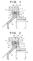
- FIGS. 1 and 3 illustrate a seal structure according to a first embodiment of the present invention
- FIG. 2 illustrates a seal structure according to a second embodiment of the present invention. Portions common or similar to all of the embodiments of the present invention are denoted with the same reference numerals throughout all of the embodiments of the present invention.
- a seal structure between a rotatable member and a stationary member includes a stationary member 2 having an interior therein, a rotatable member 3 rotatably disposed within the stationary member 2 and dividing said interior of the stationary member 2 into a first chamber 5 and a second chamber 4 having a higher pressure than the first chamber 5, a seal member 1 as a seal between the first chamber 5 and the second chamber 4, and a recess 7 for collecting grease formed in at least one of the rotatable member 3 and the stationary member 1.
- the seal member 1 is a solid or hollow ring made from elastic material (for example, rubber, synthetic resin, and metal).
- the seal member 1 is continuous in the circumferential direction thereof.
- the seal member 1 is pressed to the rotatable member 3 and the stationary member 2 at a first contact portion 11 and a second contact portion 12, respectively.
- the first contact portion 11 and the second contact portion 12 are located on one radial side of the seal member 1.
- the seal member 1 is pressed to the rotatable member 3 and the stationary member 2 at the first contact portion 11 and the second contact portion 12 due to a radial force generated by a hoop stress acting in the seal member 1.
- the first contact portion 11 and the second contact portion 12 constitute a seal between the first chamber 5 and the second chamber 4.
- the rotational member 3 and the stationary member 2 define a gap 6 extending in a direction perpendicular to an axis of the seal member 1 between the first contact portion 11 and the second contact portion 12.
- the rotatable member 3 includes a first seal surface 14 at which the seal member 1 contacts the rotatable member 3, and the stationary member 2 includes a second seal surface 15 at which the seal member 1 contacts the stationary member 2.
- the first seal surface 14 and the second seal surface are tapered so as to spread in a direction away from the gap 6 toward the seal member 1.
- the recess 7 for collecting grease (lubricant) is formed in at least one of the rotatable member 3 and the stationary member 2.
- the recess 7 is located on a second chamber side of the seal member 1.
- the recess 7 is filled with grease, although other lubricants may be used.
- the grease decreases a sliding resistance between the seal member 1 and the rotatable member 3 and helps to improve the sealing characteristic of the seal member by filling a very small gap between the seal member and the rotatable and stationary members.
- a grease supply hole 8 is formed in the stationary member 2. When the amount of grease decreases, grease is supplied to the recess 7 through the hole 8.
- the rotational speed of the rotatable member 1 is relatively low, for example, equal to or lower than 100 rpm, and more particularly, equal to or lower than 10 rpm.
- the pressure difference between the pressures in the first and second chambers 4 and 5 is also relatively low, for example, equal to or lower than 2,000 mmH 2 O (19,600 Pa), but higher than 0 mmH 2 O (0 Pa). More particularly, the pressure of the second chamber (where supply air flows) is about 1,200 mmH 2 O (11,760 Pa), and the pressure of the first chamber (where exhaust gas flows) is about 400 mmH 2 O (3,920 Pa). The pressure difference is about 800 mmH 2 O (7,840 Pa).
- the above-described seal structure can be used as a seal mechanism of the air supply and gas exhaust switching mechanism 40 of the single-type regenerative combustion burner 13.
- the single-type regenerative combustion burner 13 includes a casing 34, a heat storage member 30 (made from, for example, ceramics) which is a gas passable member and is housed in each cylinder 31 disposed within the casing 34, a burner tile 62 disposed on one axial side of the heat storage member 30, the air supply and gas exhaust switching mechanism 40 disposed on the other axial side of the heat storage member 30, and a fuel supply nozzle (fuel expelling nozzle) 60 extending through the air supply and gas exhaust switching mechanism 40 and the heat storage member 30 to the burner tile 62.
- a heat storage member 30 made from, for example, ceramics
- the heat storage member 30 retrieves a portion of heat of the exhaust gas (having a temperature above about 1,000°C) to store the heat therein and to reduce the temperature of the exhaust gas to about 250 °C when the exhaust gas flows through the heat storage member 30, and releases the heat to the supply air for combustion (having a temperature substantially equal to the ambient temperature) to preheat the supply air to about 900 °C when flow in the heat storage member is switched from the exhaust gas flow to a supply air flow.
- the transverse cross-section of the heat storage member 30 is divided into a plurality of sections. When the exhaust gas flows through some part of the sections, the supply air flows through the remaining sections. Air supply and gas exhaust is alternately switched by the air supply and gas exhaust switching mechanism 40.
- the burner tile 62 is made from ceramics or heat-resistant metals.
- the burner tile 62 includes an air supply and gas exhaust surface 63 and a protrusion 64 protruding ahead from the air supply and gas exhaust surface 63.
- a fuel release surface 65 is formed from an inside surface of the protrusion 64 to a front end surface of the protrusion 64.
- a plurality of air supply and gas exhaust holes 66 are formed in the burner tile and are open to the air supply and gas exhaust surface 63.
- the air supply and gas exhaust holes 66 and the plurality of sections of heat storage member 30 are in a one-to-one correspondence with each other. Therefore, when the exhaust gas flows through a part of the air supply and gas exhaust holes 66, the supply air flows through the remaining part of the air supply and gas exhaust holes 66.
- the air supply and gas exhaust switching mechanism 40 includes the rotatable member 3, the stationary member 2 and a dividing wall 41.
- the stationary member 2 includes a plurality of penetration holes 47 in a one-to-one correspondence with the sections of the heat storage member 30.
- the rotatable member 3 includes an aperture 42 formed on one side of the dividing wall 41 and another aperture 43 formed on the other side of the dividing wall 41.
- the aperture 42 communicates with a supply air inlet 51 and the aperture 43 communicates with an exhaust gas exit 52.
- the rotatable member 3 is rotated in one direction, or in opposite directions, by a drive device 45 (a motor or a cylinder).
- the seal structure is applied to the seal mechanism between the rotatable member 3 and the stationary member 2.
- An interior of the stationary member 2 of the air supply and gas exhaust switching mechanism 40 is divided into the first chamber 5 and the second chamber 4 by the rotatable member 3.
- Supply air flows through the second chamber 4 and exhaust gas flows through the first chamber 5.
- a pressure of the supply air is, for example, 1,200 mmH 2 O (11,760 Pa) and is higher than a pressure of the exhaust gas (for example, 400 mmH 2 O (3,920 Pa)). Therefore, there is a pressure difference between the two chambers 4 and 5.
- the temperature of the supply air is room temperature
- the temperature of the exhaust gas at a downstream end of the heat storage member in the exhaust gas flow direction is about 250°C.
- the recess 7 for collecting grease is formed on the second chamber side of the seal member 1.
- the grease supply hole 8 is formed in the stationary member 8.
- the rotatable member 3 has a portion 17 which is exposed to an exhaust gas flow.
- a groove 9 is formed in the rotatable member 3 between the portion 17 and the first contact portion 11.
- the groove 9 is open to the second chamber 4.
- the air takes away heat which is conducted from the wall of the portion 17 toward the first contact portion 11 to cool the portion where the seal member 1 is disposed.
- a fin structure having at least one fin 10 exposed to the atmosphere is formed in a portion of the stationary member 2 which is located radially outside of the seal member 1 so that the portion where the seal member 1 is disposed can be cooled due to heat convection at the fin structure.
- the seal member 1 is permitted to be made from rubber. More particularly, an O-ring made from rubber (heat-resistant rubber) having a solid or hollow cross-section is used as the seal member 1.
- seal member 1 Since the seal member 1 is mildly pressed to the rotatable member 3 and the stationary member 2 due to the radial force generated by the hoop stress of the seal member 1, a resistance between the rotatable member 3 and the seal member 1 is small. As a result, deformation and abrasion of the seal member 1 are prevented, resulting in increasing the life of the seal member 1.
- the seal member 1 Since the first seal surface 14 and the second seal surface 15 spread in the direction away from the gap 6, the seal member 1 is prevented from being dislocated from the gap so that the reliability of the seal structure is high.
- the seal structure is obtained by merely disposing the seal member 1 so that the seal member 1 is pressed to the rotatable member 3 and the stationary member 2 at the first contact portion 11 and the second contact portion 12, respectively, the structure is very simple. As a result, great cost reduction is achieved, and maintenance is easy.
- the grease can easily flow toward the seal member 1 driven by a very small amount of leaking air which inevitably occurs at the seal member 1, thereby ensuring that grease is supplied to the seal member 1. Due to the supply of grease to the seal member 1, the seal member 1 is lubricated and abrasion of the seal member 1 is minimized. As a result, the life of the seal member 1 is increased, which reduces the number of times the seal member 1 has to be replaced.
- the seal structure By applying the seal structure to the seal mechanism of the air supply and gas exhaust switching mechanism 40 of the regenerative combustion burner, the operational reliability of the burner is improved and cost reductions of the burner are achieved. If air leakage occurs from supply air to exhaust gas in the switching mechanism 40, a ratio of the supply air to fuel deviates from that of the objective, so that imperfect combustion may occur and the combustion efficiency may be lowered due to a loss of supply air energy. However, in the present invention, those undesirable effects are reduced.
- the temperature of the portion where the seal member 1 is disposed is further prevented from rising.
- the first contact portion 11 and the second contact portion 12 are located radially inside of the seal member 1. Also, the gap 6 is located radially inside of the seal member 1.
- the hoop stress generated in the seal member 1 is a tensile stress which generates a radial force directed radially inwardly. Due to the radial force, the seal member 1 is pressed to the first seal surface 14 at the first contact portion 11 and to the second seal surface 15 at the second contact portion 12.
- the seal structure of the first embodiment of the present invention is used in the case where the temperature of the portion where the seal member 1 is disposed is relatively high, more particularly, equal to or higher than 150 °C.
- the seal member 1 which is made from rubber shrinks due to the heat, the contact pressure between the seal member 1 at the first contact portion 11 and the second contact portion 12 increases so that the seal is enhanced.
- the pressure difference between the second chamber 4 and the first chamber 5 acts in a way to increase the diameter of the seal member 1, by designing the hoop force of the seal member 1 to be greater than a force acting on the seal member due to the pressure difference (proportional to the size of the gap 6), a net retaining force can acts at any time on the first contact portion 11 and the second contact portion 12.
- the first contact portion 11 and the second contact portion 12 are located radially outside of the seal member 1.
- the gap 6 is located radially outside of the seal member 1.
- the hoop stress generated in the seal member 1 is a compressive stress which generates a radial force directed radially outwardly. Due to the radial force, the seal member 1 is pressed to the first seal surface 14 at the first contact portion 11 and to the second seal surface 15 at the second contact portion 12.
- the seal structure of the second embodiment of the present invention is used in the case where the temperature of the portion where the seal member 1 is disposed is relatively low, for example, lower than 150°C.
- the thermal shrinkage of the seal member 1 is small.
- the contact pressure between the seal member 1 at the first contact portion 11 and the second contact portion 12 is little affected by the temperature of the seal member 1, so that the initial good seal is maintained.
- the pressure difference between the second chamber 4 and the first chamber 5 acts in a way to increase the diameter of the seal member 1, the seal is enhanced and a pressing force acts at any time on the first contact portion 11 and the second contact portion 12.
- the seal member 1 Since the seal member 1 is pressed to the first seal surface and the second seal surface due to the radial force generated by the hoop stress itself, the pressing force is mild so that the seal member is not deformed and does not cause sticking. Further, since the recess 7 for collecting grease is provided and the grease is supplied to the seal member, deformation and abrasion of the seal member 1 are effectively prevented. Since the seal structure is no more than disposing the seal member 1 at the portion to be sealed, the seal structure is very simple.
- the seal member Since the first and second seal surfaces are tapered, the seal member is prevented from being dislocated from the gap so that the seal is reliable.
- the seal structure can be used as a seal between the rotational member and the stationary member of the air supply and gas exhaust switching mechanism of the regenerative combustion burner.
- first contact portion 11 and the second contact portion 12 are located radially inside of the seal member 1, a good seal is maintained even if the portion where the seal member 1 is disposed is heated to a temperature above about 150 °C.
- first contact portion 11 and the second contact portion 12 are located radially outside of the seal member 1
- a good seal is maintained when the portion where the seal member 1 is disposed is heated to a temperature below about 150 °C, utilizing the radial force generated by the hoop stress and the pressure difference between the first chamber and the second chamber.
Landscapes
- Engineering & Computer Science (AREA)
- General Engineering & Computer Science (AREA)
- Mechanical Engineering (AREA)
- Chemical & Material Sciences (AREA)
- Combustion & Propulsion (AREA)
- Dispersion Chemistry (AREA)
- Physics & Mathematics (AREA)
- Thermal Sciences (AREA)
- Air Supply (AREA)
- Sealing Devices (AREA)
- Gas Burners (AREA)
Claims (11)
- Une structure d'étanchéité entre un élément rotatif (3) et un élément fixe (2) comprenant :un élément fixe (2) ayant une partie intérieure ;un élément rotatif (3) disposé de manière rotative à l'intérieur dudit élément fixe (2) et divisant ledit intérieur dudit élément fixe (2) en une première chambre (5) et une seconde chambre (4), de telle sorte que la seconde chambre a une pression plus élevée que ladite première chambre (5) ;un élément d'étanchéité (1) qui forme un joint d'étanchéité entre ladite première chambre (5) et ladite seconde chambre (4) fabriqué à partir d'une bague élastique, ledit élément d'étanchéité (1) étant pressé sur ledit élément rotatif (3) et ledit élément fixe (2) au niveau d'une première partie de contact (11) et d'une seconde partie de contact (12), respectivement, en raison d'une force radiale générée par une contrainte circonférentielle dans ledit élément d'étanchéité (1), dans laquelle ladite partie de contact (11) et ladite seconde partie de contact (12) sont situées sur un côté radial dudit élément d'étanchéité (1) ; etun évidement (7) destiné à recueillir la graisse, formé dans au moins un élément parmi ledit élément rotatif (3) et ledit élément fixe (2), ledit évidement (7) étant situé sur un dit côté de ladite seconde chambre dudit élément d'étanchéité (1).
- Une structure d'étanchéité selon la revendication 1, dans laquelle ledit élément d'étanchéité (1) est fabriqué en caoutchouc.
- Une structure d'étanchéité selon la revendication 1, dans laquelle ledit élément rotatif (3) et ledit élément fixe (2) définissent un espacement (6) entre ladite première partie de contact (11) et ladite seconde partie de contact (12), ledit élément rotatif (3) comprend une première surface d'étanchéité (14) au niveau de laquelle ledit élément rotatif (3) vient en contact avec ledit élément d'étanchéité (1) et ledit élément fixe (2) comprend une seconde surface d'étanchéité (15) au niveau de laquelle ledit élément fixe (2) vient en contact avec ledit élément d'étanchéité (1), ladite première surface d'étanchéité (14) et ladite seconde surface d'étanchéité (15) ayant des parties amincies s'étendant dans une direction s'éloignant dudit espacement (6) vers ledit élément d'étanchéité (1).
- Une structure d'étanchéité selon la revendication 1, dans laquelle une vitesse de rotation dudit élément rotatif (3) est inférieure à 100 t/min.
- Une structure d'étanchéité selon la revendication 1, dans laquelle une différence de pression entre ladite première chambre (5) et ladite seconde chambre (4) est supérieure à 0 mmH2O (0 Pa) mais inférieure ou égale à 2000 mmH2O (19600 Pa).
- Une structure d'étanchéité selon la revendication 1, dans laquelle ledit élément d'étanchéité (1) est exposé à une température allant d'une température ambiante jusqu'à 300°C.
- Une structure d'étanchéité selon la revendication 1, dans laquelle ledit élément rotatif (3) et ledit élément fixe (2) sont un élément rotatif et un élément fixe, respectivement, d'un mécanisme de commutation entre une entrée d'air et une sortie de gaz d'échappement (40) d'un brûleur à combustion régénérateur (13), et ladite première chambre (5) et ladite seconde chambre (4) sont une chambre permettant aux gaz d'échappement de circuler à travers elle-même et une chambre permettant à l'air entrant de circuler à travers elle-même, respectivement.
- Une structure d'étanchéité selon la revendication 7, dans laquelle ledit élément rotatif (3) comprend une partie (17) exposée à une circulation de gaz d'échappement, une rainure (9) communiquant avec ladite seconde chambre (4) est formée au niveau d'une partie dudit élément rotatif (3) entre ladite première partie de contact (11) et ladite partie (17) exposée à une circulation de gaz d'échappement.
- Une structure d'étanchéité selon la revendication 7, dans laquelle l'élément fixe (2) comprend une structure d'ailettes (10) formée au niveau d'une partie dudit élément fixe (2) située radialement à l'extérieur dudit élément d'étanchéité (1).
- Une structure d'étanchéité selon la revendication 1, dans laquelle ladite première partie de contact (11) et ladite seconde partie de contact (12) sont situées radialement à l'intérieur du centre d'une coupe transversale dudit élément d'étanchéité (1).
- Une structure d'étanchéité selon la revendication 1, dans laquelle ladite première partie de contact (11) et ladite seconde partie de contact (12) sont situées à l'extérieur du centre d'une coupe transversale dudit élément d'étanchéité (1).
Applications Claiming Priority (6)
| Application Number | Priority Date | Filing Date | Title |
|---|---|---|---|
| JP12292696 | 1996-05-17 | ||
| JP12292696 | 1996-05-17 | ||
| JP122926/96 | 1996-05-17 | ||
| JP92605/97 | 1997-04-10 | ||
| JP9092605A JP3006537B2 (ja) | 1996-05-17 | 1997-04-10 | 回転部材と固定部材との間のシール構造 |
| JP9260597 | 1997-04-10 |
Publications (2)
| Publication Number | Publication Date |
|---|---|
| EP0807774A1 EP0807774A1 (fr) | 1997-11-19 |
| EP0807774B1 true EP0807774B1 (fr) | 2002-06-05 |
Family
ID=26434003
Family Applications (1)
| Application Number | Title | Priority Date | Filing Date |
|---|---|---|---|
| EP97401088A Expired - Lifetime EP0807774B1 (fr) | 1996-05-17 | 1997-05-15 | Structure de joint entre une élément rotatif et une élément stationnaire |
Country Status (5)
| Country | Link |
|---|---|
| US (1) | US5957462A (fr) |
| EP (1) | EP0807774B1 (fr) |
| JP (1) | JP3006537B2 (fr) |
| KR (1) | KR100214043B1 (fr) |
| DE (1) | DE69712980T2 (fr) |
Families Citing this family (16)
| Publication number | Priority date | Publication date | Assignee | Title |
|---|---|---|---|---|
| US7052014B1 (en) * | 1999-02-04 | 2006-05-30 | Orlowski David C | Snap together bearing isolator |
| KR100720226B1 (ko) | 2003-02-12 | 2007-05-23 | 코가네이 코포레이션 | 진공 공급 조인트 |
| JP2005308019A (ja) * | 2004-04-19 | 2005-11-04 | Shikoku Kakoki Co Ltd | シール装置 |
| WO2006005950A2 (fr) * | 2004-07-12 | 2006-01-19 | Aes Engineering Limited | Joint isolant |
| US7096740B2 (en) * | 2004-11-17 | 2006-08-29 | The Boeing Company | Reusable preload indicating washer assembly |
| US10180189B2 (en) | 2014-12-08 | 2019-01-15 | Flowserve Management Company | Bearing isolator seal with tapered static shutoff O-ring interface |
| US10184514B2 (en) | 2014-12-18 | 2019-01-22 | Flowserve Management Company | Bearing isolator seal with enhanced rotor drive coupling |
| EP3286462B1 (fr) | 2015-04-21 | 2024-06-12 | Inpro/Seal LLC | Ensemble joint d'arbre |
| US10927961B2 (en) | 2015-04-21 | 2021-02-23 | Inpro/Seal Llc | Shaft seal assembly |
| CN104791492B (zh) * | 2015-05-07 | 2017-03-08 | 四川东能节能技术有限公司 | 空预器及其冷端径向或轴向的密封装置 |
| EP4467849A3 (fr) | 2015-06-18 | 2025-05-21 | Inpro/Seal LLC | Ensemble joint d'arbre |
| CN106051813B (zh) * | 2016-07-01 | 2017-03-22 | 四川东方能源科技股份有限公司 | 一种用于空预器径向密封片安装的组件 |
| CN106090987B (zh) * | 2016-07-01 | 2017-05-10 | 四川东方能源科技股份有限公司 | 一种用于实现空预器径向密封的密封组件 |
| CN106287790B (zh) * | 2016-08-31 | 2018-11-30 | 戴春喜 | 回转式空气预热器及其密封结构 |
| US10330204B2 (en) * | 2017-11-10 | 2019-06-25 | Rolls-Royce Deutschland Ltd & Co Kg | Burner seal of a gas turbine and method for manufacturing the same |
| CN112610708B (zh) * | 2020-12-09 | 2021-11-02 | 浙江大学 | 一种双座式调节阀及其密封结构和方法 |
Family Cites Families (15)
| Publication number | Priority date | Publication date | Assignee | Title |
|---|---|---|---|---|
| US429440A (en) * | 1890-06-03 | gordon | ||
| US2480229A (en) * | 1945-11-23 | 1949-08-30 | United Aircraft Corp | Piston rod packing lubricator |
| DE1084990B (de) * | 1958-02-24 | 1960-07-07 | Skf Svenska Kullagerfab Ab | Zentrifugaldichtung |
| US3262484A (en) * | 1964-10-09 | 1966-07-26 | Selas Corp Of America | Industrial burner with recuperative means |
| US3212558A (en) * | 1964-10-09 | 1965-10-19 | Selas Corp Of America | Industrial burner |
| DE1600523C3 (de) * | 1967-06-03 | 1974-08-01 | Sealol Inc., Warwick, R.I. (V.St.A.) | Gleitringdichtung mit einer dem Radial sich erstreckenden Dichtungsspalt zugeführten Sperrflüssigkeit |
| JPS536746A (en) * | 1976-07-07 | 1978-01-21 | Fuji Electric Co Ltd | Pelton wheel water discharge regulator |
| US4073548A (en) * | 1976-11-01 | 1978-02-14 | Dresser Industries, Inc. | Sealing system for a rotary rock bit |
| US4500098A (en) * | 1983-12-22 | 1985-02-19 | United Technologies Corporation | Gas seal for rotating components |
| US4604051A (en) * | 1984-08-16 | 1986-08-05 | Gas Research Institute | Regenerative burner |
| JP3005110B2 (ja) * | 1991-07-29 | 2000-01-31 | 靖夫 広瀬 | 熱回収式燃焼装置 |
| US5378000A (en) * | 1992-10-19 | 1995-01-03 | Inpro Companies, Inc. | Shaft seal assembly |
| US5562294A (en) * | 1994-01-28 | 1996-10-08 | Bw/Ip International, Inc. | Backup seal for axial face seal |
| US5562442A (en) * | 1994-12-27 | 1996-10-08 | Eisenmann Corporation | Regenerative thermal oxidizer |
| US5704461A (en) * | 1995-07-17 | 1998-01-06 | Horton, Inc. | Rotational control apparatus |
-
1997
- 1997-04-10 JP JP9092605A patent/JP3006537B2/ja not_active Expired - Lifetime
- 1997-05-15 US US08/856,579 patent/US5957462A/en not_active Expired - Lifetime
- 1997-05-15 EP EP97401088A patent/EP0807774B1/fr not_active Expired - Lifetime
- 1997-05-15 DE DE69712980T patent/DE69712980T2/de not_active Expired - Lifetime
- 1997-05-16 KR KR1019970018842A patent/KR100214043B1/ko not_active Expired - Fee Related
Also Published As
| Publication number | Publication date |
|---|---|
| DE69712980D1 (de) | 2002-07-11 |
| KR19980079237A (ko) | 1998-11-25 |
| JPH1038092A (ja) | 1998-02-13 |
| EP0807774A1 (fr) | 1997-11-19 |
| JP3006537B2 (ja) | 2000-02-07 |
| US5957462A (en) | 1999-09-28 |
| DE69712980T2 (de) | 2003-01-23 |
| KR100214043B1 (ko) | 1999-08-02 |
Similar Documents
| Publication | Publication Date | Title |
|---|---|---|
| EP0807774B1 (fr) | Structure de joint entre une élément rotatif et une élément stationnaire | |
| EP0818607B1 (fr) | Turbine à gaz avec barrière contre la contamination pour garniture étanche en carbone | |
| US4222575A (en) | Shaft seal device | |
| JP3555683B2 (ja) | 回転機用シールアセンブリ | |
| US5626347A (en) | Coning resistant face seal having a "U" shape | |
| JP3594600B2 (ja) | 耐逆圧性シール手段 | |
| CA1081190A (fr) | Pompe ou compresseur volumetrique de type rotatif | |
| US9303721B2 (en) | High speed flywheel | |
| US4328860A (en) | Recuperator for heat exchange between flow media of dissimilar temperatures | |
| JP2015522735A (ja) | 配管一体型スプーリ金属シール半体 | |
| US5544896A (en) | Composite face seal | |
| JPH0495665A (ja) | スターリングエンジン用シール装置 | |
| US4474106A (en) | Fluidic self adjusting seal assembly | |
| US10767565B2 (en) | System and method for sealing a fluid system in a safety condition | |
| US3999894A (en) | Compressor assembly | |
| CN116480780A (zh) | 组合式密封装置 | |
| JPH07224948A (ja) | メカニカルシール | |
| EP0266664A2 (fr) | Disposition d'un boîtier pour presse-étoupes | |
| US6338491B1 (en) | Rotary shaft seal | |
| US7134416B2 (en) | Rotary valve seal | |
| FI62712B (fi) | Kugghjulspump och/eller -motor | |
| JP3801742B2 (ja) | 温度感応型ファン・ドライブ | |
| KR102376470B1 (ko) | 멀티웨이밸브 장치 | |
| US4222720A (en) | Corner seal means for rotary piston engines | |
| US7305937B2 (en) | Rotary toroidal machine with piston connecting mechanism |
Legal Events
| Date | Code | Title | Description |
|---|---|---|---|
| PUAI | Public reference made under article 153(3) epc to a published international application that has entered the european phase |
Free format text: ORIGINAL CODE: 0009012 |
|
| 17P | Request for examination filed |
Effective date: 19970523 |
|
| AK | Designated contracting states |
Kind code of ref document: A1 Designated state(s): DE FR GB |
|
| GRAG | Despatch of communication of intention to grant |
Free format text: ORIGINAL CODE: EPIDOS AGRA |
|
| 17Q | First examination report despatched |
Effective date: 20010918 |
|
| GRAG | Despatch of communication of intention to grant |
Free format text: ORIGINAL CODE: EPIDOS AGRA |
|
| GRAH | Despatch of communication of intention to grant a patent |
Free format text: ORIGINAL CODE: EPIDOS IGRA |
|
| GRAH | Despatch of communication of intention to grant a patent |
Free format text: ORIGINAL CODE: EPIDOS IGRA |
|
| GRAA | (expected) grant |
Free format text: ORIGINAL CODE: 0009210 |
|
| AK | Designated contracting states |
Kind code of ref document: B1 Designated state(s): DE FR GB |
|
| REG | Reference to a national code |
Ref country code: GB Ref legal event code: FG4D |
|
| REF | Corresponds to: |
Ref document number: 69712980 Country of ref document: DE Date of ref document: 20020711 |
|
| GRAH | Despatch of communication of intention to grant a patent |
Free format text: ORIGINAL CODE: EPIDOS IGRA |
|
| ET | Fr: translation filed | ||
| PLBE | No opposition filed within time limit |
Free format text: ORIGINAL CODE: 0009261 |
|
| STAA | Information on the status of an ep patent application or granted ep patent |
Free format text: STATUS: NO OPPOSITION FILED WITHIN TIME LIMIT |
|
| 26N | No opposition filed |
Effective date: 20030306 |
|
| REG | Reference to a national code |
Ref country code: GB Ref legal event code: 746 Effective date: 20130215 |
|
| REG | Reference to a national code |
Ref country code: DE Ref legal event code: R084 Ref document number: 69712980 Country of ref document: DE Effective date: 20130312 |
|
| PGFP | Annual fee paid to national office [announced via postgrant information from national office to epo] |
Ref country code: DE Payment date: 20130515 Year of fee payment: 17 Ref country code: GB Payment date: 20130515 Year of fee payment: 17 |
|
| PGFP | Annual fee paid to national office [announced via postgrant information from national office to epo] |
Ref country code: FR Payment date: 20130531 Year of fee payment: 17 |
|
| REG | Reference to a national code |
Ref country code: DE Ref legal event code: R119 Ref document number: 69712980 Country of ref document: DE |
|
| GBPC | Gb: european patent ceased through non-payment of renewal fee |
Effective date: 20140515 |
|
| REG | Reference to a national code |
Ref country code: DE Ref legal event code: R119 Ref document number: 69712980 Country of ref document: DE Effective date: 20141202 |
|
| REG | Reference to a national code |
Ref country code: FR Ref legal event code: ST Effective date: 20150130 |
|
| PG25 | Lapsed in a contracting state [announced via postgrant information from national office to epo] |
Ref country code: DE Free format text: LAPSE BECAUSE OF NON-PAYMENT OF DUE FEES Effective date: 20141202 |
|
| PG25 | Lapsed in a contracting state [announced via postgrant information from national office to epo] |
Ref country code: GB Free format text: LAPSE BECAUSE OF NON-PAYMENT OF DUE FEES Effective date: 20140515 Ref country code: FR Free format text: LAPSE BECAUSE OF NON-PAYMENT OF DUE FEES Effective date: 20140602 |