EP0807729A2 - Automobile door handle - Google Patents
Automobile door handle Download PDFInfo
- Publication number
- EP0807729A2 EP0807729A2 EP97301751A EP97301751A EP0807729A2 EP 0807729 A2 EP0807729 A2 EP 0807729A2 EP 97301751 A EP97301751 A EP 97301751A EP 97301751 A EP97301751 A EP 97301751A EP 0807729 A2 EP0807729 A2 EP 0807729A2
- Authority
- EP
- European Patent Office
- Prior art keywords
- handle
- lever
- automobile door
- case
- grip
- Prior art date
- Legal status (The legal status is an assumption and is not a legal conclusion. Google has not performed a legal analysis and makes no representation as to the accuracy of the status listed.)
- Granted
Links
- 230000003014 reinforcing effect Effects 0.000 claims abstract description 18
- 230000002452 interceptive effect Effects 0.000 claims abstract description 3
- 230000002093 peripheral effect Effects 0.000 description 4
- 238000000034 method Methods 0.000 description 1
- 238000012986 modification Methods 0.000 description 1
- 230000004048 modification Effects 0.000 description 1
- 239000011347 resin Substances 0.000 description 1
- 229920005989 resin Polymers 0.000 description 1
Images


Classifications
-
- E—FIXED CONSTRUCTIONS
- E05—LOCKS; KEYS; WINDOW OR DOOR FITTINGS; SAFES
- E05B—LOCKS; ACCESSORIES THEREFOR; HANDCUFFS
- E05B85/00—Details of vehicle locks not provided for in groups E05B77/00 - E05B83/00
- E05B85/10—Handles
-
- E—FIXED CONSTRUCTIONS
- E05—LOCKS; KEYS; WINDOW OR DOOR FITTINGS; SAFES
- E05B—LOCKS; ACCESSORIES THEREFOR; HANDCUFFS
- E05B85/00—Details of vehicle locks not provided for in groups E05B77/00 - E05B83/00
- E05B85/10—Handles
- E05B85/14—Handles pivoted about an axis parallel to the wing
- E05B85/16—Handles pivoted about an axis parallel to the wing a longitudinal grip part being pivoted at one end about an axis perpendicular to the longitudinal axis of the grip part
-
- Y—GENERAL TAGGING OF NEW TECHNOLOGICAL DEVELOPMENTS; GENERAL TAGGING OF CROSS-SECTIONAL TECHNOLOGIES SPANNING OVER SEVERAL SECTIONS OF THE IPC; TECHNICAL SUBJECTS COVERED BY FORMER USPC CROSS-REFERENCE ART COLLECTIONS [XRACs] AND DIGESTS
- Y10—TECHNICAL SUBJECTS COVERED BY FORMER USPC
- Y10T—TECHNICAL SUBJECTS COVERED BY FORMER US CLASSIFICATION
- Y10T292/00—Closure fasteners
- Y10T292/08—Bolts
- Y10T292/096—Sliding
- Y10T292/1014—Operating means
- Y10T292/1017—Flexible
-
- Y—GENERAL TAGGING OF NEW TECHNOLOGICAL DEVELOPMENTS; GENERAL TAGGING OF CROSS-SECTIONAL TECHNOLOGIES SPANNING OVER SEVERAL SECTIONS OF THE IPC; TECHNICAL SUBJECTS COVERED BY FORMER USPC CROSS-REFERENCE ART COLLECTIONS [XRACs] AND DIGESTS
- Y10—TECHNICAL SUBJECTS COVERED BY FORMER USPC
- Y10T—TECHNICAL SUBJECTS COVERED BY FORMER US CLASSIFICATION
- Y10T292/00—Closure fasteners
- Y10T292/57—Operators with knobs or handles
Definitions
- the present invention relates to an automobile door handle, and particularly to an automobile door handle having a handle grip and a handle case.
- JP-U Japanese Utility Model Application Laid-Open
- Japanese Utility Model Application Laid-Open (JP-U) No. 63-23448 discloses a grip-type handle in which a handle and a door lock releasing mechanism are connected by a rod.
- Japanese Utility Model Application Laid-Open (JP-U) No. 63-152868 discloses a grip-type handle having a lever which is rotatably supported by a base.
- Japanese Patent Application Laid-Open (JP-A) No. 7-331931 discloses a grip-type handle in which an engaging hole, with which a lever is engaged, is formed in a sliding portion of the handle.
- JP-U Japanese Utility Model Application Laid-Open
- one end portion 74A of a handle grip 74 is connected to one end portion 72A of a handle case 72 fixed to a side door 71 and the handle grip 74 is provided to be swingable, with respect to the handle case 72, around a portion at which the end portion 74A is connected to the end portion 72A in upward and downward directions on the paper of Fig. 5 (i.e., the directions indicated by double-headed arrow S).
- a lever 80 is rotatably supported by a pin 78 on a protruding arm 76 provided at another end 72B of the handle case 72.
- the lever 80 is engaged with a concave portion 84 which is formed at a vicinity of a tip end portion of a circular arc-shaped projecting member 82 provided in another end portion 74B of the handle grip 74.
- the circular arc-shaped projecting member 82 is provided to pass through a through hole 86 formed in the handle case 72. Accordingly, when the handle grip 74 swings and moves from the position indicated by the solid line in Fig. 5 to that indicated by the two-dot chain line, the lever 80 engaged with the concave portion 84 of the circular arc-shaped projecting member 82 rotates so that locking of the side door 71 is released.
- a first aspect of the present invention is an automobile door handle which comprises: a handle grip including a rotating shaft portion formed at one end of the handle grip, and a handle sliding portion formed at another end of the handle grip and having an engaged portion; a handle case including a rotating shaft mounting portion in which the rotating shaft portion is rotatably mounted, and a slide hole in which the handle sliding portion is inserted; and a lever including a wire connecting portion to which a wire connected to a door lock releasing mechanism is connected, and an engaging portion engaged with the engaged portion, the lever being rotatably supported by the handle case, wherein a reinforcing portion is provided within the slide hole and a recessed portion is provided in the handle sliding portion to prevent the handle sliding portion and the reinforcing portion from interfering with each other.
- the handle sliding portion of the handle grip slides within the slide hole formed in the handle case.
- the handle sliding portion and the reinforcing portion do not interfere with each other by the recessed portion.
- the lever engaged with the engaged portion of the handle sliding portion rotates to move the wire connected to the wire connecting portion of the lever and to the door lock releasing mechanism, and the door lock is thereby released.
- the supporting strength of the lever can be improved without the handle case being made larger.
- a second aspect of the present invention is an automobile door handle, and in the first aspect of the present invention the reinforcing portion is provided so as to abut against the lever.
- Fig. 1 is a perspective view showing an automobile door handle according to an embodiment of the present invention.
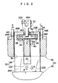
- Fig. 2 is a cross-sectional view taken along the lines 2-2 in Fig. 1.
- Fig. 3 is an enlarged perspective view, partly in cross section, of an automobile door handle according to another embodiment of the present invention.
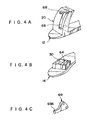
- Fig. 4A is a perspective view showing a handle grip of an automobile door handle according to yet another embodiment of the present invention.
- Fig. 4B is a perspective view showing a handle case of the automobile door handle according to the yet another embodiment of the present invention.
- Fig. 4C is a perspective view showing a lever of the automobile door handle according to the yet another embodiment of the present invention.
- Fig. 5 is a side view showing a conventional automobile door handle.
- an automobile door handle 10 of the present invention includes a handle grip 12 and a handle case 14.
- Formed in one end portion 12A of the handle grip 12 are rotating shaft portions 16 which are respectively provided to project in opposite directions transversely from the handle grip 12 (i.e., the directions indicated by double-head arrow W in Fig. 1).
- These rotating shaft portions 16 are respectively supported rotatably by a pair of rotating shaft mounting portions 18 formed at positions near one end portion 14A of the handle case 14.
- the handle grip 12 is provided to be swingable around the rotating shaft portions 16 with respect to the handle case 14 in directions in which the handle grip 12 moves away from and close to the handle case 14 (i.e., the directions indicated by arrow A and arrow B in Fig. 1).
- a handle sliding portion 20 is formed in another end portion 12B of the handle grip 12 so as to face the handle case 14.
- the handle sliding portion 20 is formed from a pair of facing columnar bodies 22, 24. These columnar bodies 22, 24 are formed to be bent along a locus of rotation of the handle grip 12.
- respective base portions 22A, 24A of the columnar bodies 22, 24 are connected to each other.
- Engaged portions 26, 28 are respectively formed in end portions 22B, 24B of the columnar bodies 22, 24 at positions where the end portions 22B, 24B face each other.
- the handle sliding portion 20 is inserted in a slide hole 30 formed in the handle case 14 in such a manner as to be slidable within the slide hole 30.
- the end portions 22B, 24B of the columnar bodies 22, 24 of the handle sliding portion 20 are respectively provided to project toward a back side of the handle case 14 (i.e., toward an upper side on the paper of Fig. 2).
- Case ribs 14B, 14C are provided on the back side of the handle case 14 along the direction to which the columnar bodies 22, 24 project, and inclinations of the columnar bodies 22, 24 in transversely outward directions of the handle case 14 (i.e., the directions indicated by arrow C and arrow D in Fig. 2) is thereby prevented. Further, end portions 34A, 34B of an engaging shaft portion 34 which is formed, as an engaging portion, at an end portion of a lever 32 are respectively engaged with the engaged portions 26, 28 of the handle sliding portion 20.
- a case stopper rib 40 serving as a reinforcing portion is integrally formed at the central portion of the sliding hole 30 formed in the handle case 14.
- the case stopper rib 40 is disposed within a recessed portion 41 formed between the columnar bodies 22, 24 and an intermediate portion 34C of the engaging shaft portion 34 of the lever 32 abuts against an end surface 40C of the case stopper rib 40.
- the lever 32 is supported to be rotatable around a rotating shaft 42 and both end portions of the rotating shaft 42 are supported by the case ribs 14B, 14C, respectively.
- the lever 32 is provided to be rotatable around the rotating shaft 42 in directions where the lever 32 moves away from and close to the case stopper rib 40 (i.e., the directions indicated by arrow E and arrow F in Fig. 1).
- a coil spring 44 is wound around the rotating shaft 42 and one end portion of the coil spring 44 is engaged with the case rib 14B.
- Another end portion of the coil spring 44 is fixed to the lever 32 and the coil spring 44 causes the lever 32 to be urged in a direction where the engaging shaft portion 34 moves away from the case stopper rib 40 (i.e., the direction indicated by arrow E in Fig. 1).
- a wire supporting portion 46 is provided vertically on the back surface of the handle case 14 and an end portion 50A of a tube 50 of a wire 48 connected to a door lock releasing mechanism is fixed to the wire supporting portion 46. Further, one end portion of the wire is fixed to an anchor 48A and the anchor 48A is engaged with a wire connecting portion 32A of the lever 32. Accordingly, when the lever 32 rotates in the direction indicated by arrow F in Fig. 1 against urging force of the coil spring 44, the wire 48 is pulled out from the end portion 50A of the tube 50 so that locking of the door is released.
- the handle grip 12 swings around the rotating shaft portions 16 with respect to the handle case 14 in the direction indicated by arrow A.
- the handle sliding portion 20 formed in the handle grip 12 slides within the slide hole 30 and the lever 32 with the engaging shaft portion 34 is engaged with the engaged portions 26, 28 of the handle sliding portion 20 rotates in the direction indicated by arrow F against the urging force of the coil spring 44.
- the lever 32 rotates in the direction indicated by arrow F, the wire 48 is pulled out from the end portion 50A of the tube 50 and locking of the door is thereby released.
- the intermediate portion 34C of the engaging shaft portion 34 of the lever 32 abuts against the case stopper rib 40.
- the present embodiment is constructed in that the handle sliding portion 20 is formed by the pair of facing columnar bodies 22, 24 and the case stopper rib 40 is formed between these columnar bodies 22, 24 within the slide hole 30 of the handle case 14, a region of the handle case 14 in which the slide hole 30 is formed can be reinforced without the thickness of the peripheral portion of the slide hole 30 being made larger. For this reason, there is no possibility that the handle case 14 be made larger.
- the handle grip operating loads F1, F2 are not directly applied to other regions of the lever 32, it is unnecessary to reinforce the entire lever 32. Further, since the lever 32 is formed of a resin member, reduction in cost therefor can be achieved.
- the central portion of the slide hole 30 of the handle case 14 is reinforced by the case stopper rib 40 so that the slide hole 30 can be effectively reinforced.
- the case stopper rib 40 is integrally formed within the slide hole 30 formed in the handle case 14.
- a case stopper rib 140 formed separately from the handle case 14 may be mounted between notches 60, 62 formed in an external wall portion of the slide hole 30.
- the case stopper rib 40 is provided at the central portion of the slide hole 30, but the position of the case stopper rib 40 is not limited to the central portion of the slide hole 30.
- the recessed portion 41 is formed between the columnar bodies 22, 24 of the handle sliding portion 20, but the position of the recessed portion 41 is not limited to that between the columnar bodies 22, 24. It suffices that the recessed portion 41 be disposed at any position where the recessed portion 41 does not interfere with the case stopper rib 40.
- the structure provided by the present embodiment is such that the lever 32 abuts against the case stopper rib 40 which serves as the reinforcing portion.
- a recessed portion 66 provided to correspond to a reinforcing portion 64 shown in Fig. 4B is formed in the handle sliding portion 20 in such a manner that the reinforcing portion abuts against an end portion of the recessed portion 66 when the handle grip 12 swings to move away from the handle case 14, and an end portion 69A of a lever 69 shown in Fig. 4C is engaged with an engaged portion 68 formed in the handle sliding portion 20 at a position separated from the recessed portion 66 by a predetermined distance.
Landscapes
- Lock And Its Accessories (AREA)
Abstract
Description
- The present invention relates to an automobile door handle, and particularly to an automobile door handle having a handle grip and a handle case.
- Conventionally, as an automobile door handle having a handle grip and a handle case, the structure disclosed in Japanese Utility Model Application Laid-Open (JP-U) No. 63-125669 has been known.
- Japanese Utility Model Application Laid-Open (JP-U) No. 63-23448 discloses a grip-type handle in which a handle and a door lock releasing mechanism are connected by a rod. Japanese Utility Model Application Laid-Open (JP-U) No. 63-152868 discloses a grip-type handle having a lever which is rotatably supported by a base. Further, Japanese Patent Application Laid-Open (JP-A) No. 7-331931 discloses a grip-type handle in which an engaging hole, with which a lever is engaged, is formed in a sliding portion of the handle.
- The structure disclosed in Japanese Utility Model Application Laid-Open (JP-U) No. 63-125669 will be described hereinafter.
- As shown in Fig. 5, in an
automobile door handle 70, oneend portion 74A of ahandle grip 74 is connected to oneend portion 72A of ahandle case 72 fixed to aside door 71 and thehandle grip 74 is provided to be swingable, with respect to thehandle case 72, around a portion at which theend portion 74A is connected to theend portion 72A in upward and downward directions on the paper of Fig. 5 (i.e., the directions indicated by double-headed arrow S). Alever 80 is rotatably supported by apin 78 on a protrudingarm 76 provided at anotherend 72B of thehandle case 72. Thelever 80 is engaged with a concave portion 84 which is formed at a vicinity of a tip end portion of a circular arc-shaped projecting member 82 provided in anotherend portion 74B of thehandle grip 74. The circular arc-shaped projecting member 82 is provided to pass through a throughhole 86 formed in thehandle case 72. Accordingly, when the handle grip 74 swings and moves from the position indicated by the solid line in Fig. 5 to that indicated by the two-dot chain line, thelever 80 engaged with the concave portion 84 of the circular arc-shaped projecting member 82 rotates so that locking of theside door 71 is released. - However, in this automobile door handle 70, when the handle grip 74 swings and moves to the position indicated by the two-dot chain line in Fig. 5, the
lever 80 abuts against an outer peripheral edge of the throughhole 86 of thehandle case 72 to prevent thehandle grip 74 to slip out of the throughhole 86. For this reason, a great load is applied to the outer peripheral edge of thethrough hole 86. Accordingly, it is considered that the outer peripheral edge of thethrough hole 86 is reinforced by increasing the thickness M thereof. However, in this case, since thedoor handle 70 becomes larger, this method is not preferable. - In view of the above-described circumstances, it is an object of the present invention to provide an automobile door handle in which the supporting strength of a lever can be improved without a handle case being made larger.
- A first aspect of the present invention is an automobile door handle which comprises: a handle grip including a rotating shaft portion formed at one end of the handle grip, and a handle sliding portion formed at another end of the handle grip and having an engaged portion; a handle case including a rotating shaft mounting portion in which the rotating shaft portion is rotatably mounted, and a slide hole in which the handle sliding portion is inserted; and a lever including a wire connecting portion to which a wire connected to a door lock releasing mechanism is connected, and an engaging portion engaged with the engaged portion, the lever being rotatably supported by the handle case, wherein a reinforcing portion is provided within the slide hole and a recessed portion is provided in the handle sliding portion to prevent the handle sliding portion and the reinforcing portion from interfering with each other.
- Accordingly, when the handle grip swings around the rotating shaft portion with respect to the handle case, the handle sliding portion of the handle grip slides within the slide hole formed in the handle case. At this time, the handle sliding portion and the reinforcing portion do not interfere with each other by the recessed portion.
- Further, when the handle sliding portion slides within the slide hole, the lever engaged with the engaged portion of the handle sliding portion rotates to move the wire connected to the wire connecting portion of the lever and to the door lock releasing mechanism, and the door lock is thereby released. As a result, the supporting strength of the lever can be improved without the handle case being made larger.
- A second aspect of the present invention is an automobile door handle, and in the first aspect of the present invention the reinforcing portion is provided so as to abut against the lever.
- Accordingly, load applied to the lever by the handle grip when a full stroke of a handle is made (i.e., when door lock is released) is effectively absorbed by contact surfaces of the lever and the reinforcing portion. Further, it is not necessary to reinforce the lever and the handle case supporting portion of the lever to high strength.
- Fig. 1 is a perspective view showing an automobile door handle according to an embodiment of the present invention.
- Fig. 2 is a cross-sectional view taken along the lines 2-2 in Fig. 1.
- Fig. 3 is an enlarged perspective view, partly in cross section, of an automobile door handle according to another embodiment of the present invention.
- Fig. 4A is a perspective view showing a handle grip of an automobile door handle according to yet another embodiment of the present invention.
- Fig. 4B is a perspective view showing a handle case of the automobile door handle according to the yet another embodiment of the present invention.
- Fig. 4C is a perspective view showing a lever of the automobile door handle according to the yet another embodiment of the present invention.
- Fig. 5 is a side view showing a conventional automobile door handle.
- Referring now to Figs. 1 and 2, a description will be given of an embodiment of an automobile door handle of the present invention.
- As shown in Fig. 1, an
automobile door handle 10 of the present invention includes ahandle grip 12 and ahandle case 14. Formed in oneend portion 12A of thehandle grip 12 are rotatingshaft portions 16 which are respectively provided to project in opposite directions transversely from the handle grip 12 (i.e., the directions indicated by double-head arrow W in Fig. 1). These rotatingshaft portions 16 are respectively supported rotatably by a pair of rotatingshaft mounting portions 18 formed at positions near oneend portion 14A of thehandle case 14. - Accordingly, the
handle grip 12 is provided to be swingable around the rotatingshaft portions 16 with respect to thehandle case 14 in directions in which thehandle grip 12 moves away from and close to the handle case 14 (i.e., the directions indicated by arrow A and arrow B in Fig. 1). - A
handle sliding portion 20 is formed in another end portion 12B of thehandle grip 12 so as to face thehandle case 14. Thehandle sliding portion 20 is formed from a pair of facingcolumnar bodies columnar bodies handle grip 12. - As shown in Fig. 2,
respective base portions columnar bodies portions end portions columnar bodies end portions handle sliding portion 20 is inserted in aslide hole 30 formed in thehandle case 14 in such a manner as to be slidable within theslide hole 30. Meanwhile, theend portions columnar bodies handle sliding portion 20 are respectively provided to project toward a back side of the handle case 14 (i.e., toward an upper side on the paper of Fig. 2). -
Case ribs handle case 14 along the direction to which thecolumnar bodies columnar bodies end portions 34A, 34B of anengaging shaft portion 34 which is formed, as an engaging portion, at an end portion of alever 32 are respectively engaged with the engagedportions handle sliding portion 20. - A
case stopper rib 40 serving as a reinforcing portion is integrally formed at the central portion of thesliding hole 30 formed in thehandle case 14. Thecase stopper rib 40 is disposed within a recessedportion 41 formed between thecolumnar bodies intermediate portion 34C of theengaging shaft portion 34 of thelever 32 abuts against anend surface 40C of thecase stopper rib 40. - As shown in Fig. 1, the
lever 32 is supported to be rotatable around a rotatingshaft 42 and both end portions of the rotatingshaft 42 are supported by thecase ribs lever 32 is provided to be rotatable around the rotatingshaft 42 in directions where thelever 32 moves away from and close to the case stopper rib 40 (i.e., the directions indicated by arrow E and arrow F in Fig. 1). Further, acoil spring 44 is wound around the rotatingshaft 42 and one end portion of thecoil spring 44 is engaged with thecase rib 14B. Another end portion of thecoil spring 44 is fixed to thelever 32 and thecoil spring 44 causes thelever 32 to be urged in a direction where theengaging shaft portion 34 moves away from the case stopper rib 40 (i.e., the direction indicated by arrow E in Fig. 1). - A
wire supporting portion 46 is provided vertically on the back surface of thehandle case 14 and anend portion 50A of atube 50 of awire 48 connected to a door lock releasing mechanism is fixed to thewire supporting portion 46. Further, one end portion of the wire is fixed to ananchor 48A and theanchor 48A is engaged with awire connecting portion 32A of thelever 32. Accordingly, when thelever 32 rotates in the direction indicated by arrow F in Fig. 1 against urging force of thecoil spring 44, thewire 48 is pulled out from theend portion 50A of thetube 50 so that locking of the door is released. - Next, an operation of the present embodiment will be described.
- In the present embodiment, when a vehicle occupant's hand is moved in the direction indicated by arrow A in Fig. 1 with the
handle grip 12 being held by the occupant's hand, thehandle grip 12 swings around the rotatingshaft portions 16 with respect to thehandle case 14 in the direction indicated by arrow A. When thehandle grip 12 swings, thehandle sliding portion 20 formed in thehandle grip 12 slides within theslide hole 30 and thelever 32 with theengaging shaft portion 34 is engaged with the engagedportions handle sliding portion 20 rotates in the direction indicated by arrow F against the urging force of thecoil spring 44. When thelever 32 rotates in the direction indicated by arrow F, thewire 48 is pulled out from theend portion 50A of thetube 50 and locking of the door is thereby released. - At this time, in the
automobile door handle 10 of the present embodiment, theintermediate portion 34C of the engagingshaft portion 34 of thelever 32 abuts against thecase stopper rib 40. - As described above, since the present embodiment is constructed in that the
handle sliding portion 20 is formed by the pair of facingcolumnar bodies case stopper rib 40 is formed between thesecolumnar bodies slide hole 30 of thehandle case 14, a region of thehandle case 14 in which theslide hole 30 is formed can be reinforced without the thickness of the peripheral portion of theslide hole 30 being made larger. For this reason, there is no possibility that thehandle case 14 be made larger. - Further, as shown in Fig. 2, in the present embodiment, in the state in which the
intermediate portion 34C of the engagingshaft portion 34 of thelever 32 abuts against thecase stopper rib 40, handle grip operating loads F1, F2 respectively applied to theend portions 34A, 34B of the engagingshaft portion 34 via the engagedportions handle sliding portion 20 can be received by theend surface 40C of thecase stopper rib 40 which abuts against theintermediate portion 34C of the engagingshaft portion 34. - Accordingly, the handle grip operating loads F1, F2 form load F3 (F3 = F1 + F2) to be efficiently transmitted to the
case stopper rib 40 via the engagingshaft portion 34. For this reason, since the handle grip operating loads F1, F2 are not directly applied to other regions of thelever 32, it is unnecessary to reinforce theentire lever 32. Further, since thelever 32 is formed of a resin member, reduction in cost therefor can be achieved. - In addition, in the present embodiment, the central portion of the
slide hole 30 of thehandle case 14 is reinforced by thecase stopper rib 40 so that theslide hole 30 can be effectively reinforced. - In the foregoing, although the present invention was described in detail with reference to the specified embodiment, it is not limited to the same, and it will become clear to those skilled in the art that other various modifications may be made within the scope of the invention as hereinafter claimed. For example, in the present embodiment, the
case stopper rib 40 is integrally formed within theslide hole 30 formed in thehandle case 14. However, as shown in Fig. 3, in place of this structure, acase stopper rib 140 formed separately from thehandle case 14 may be mounted betweennotches 60, 62 formed in an external wall portion of theslide hole 30. - Further, in the present embodiment, the
case stopper rib 40 is provided at the central portion of theslide hole 30, but the position of thecase stopper rib 40 is not limited to the central portion of theslide hole 30. Moreover, in the present embodiment, the recessedportion 41 is formed between thecolumnar bodies handle sliding portion 20, but the position of the recessedportion 41 is not limited to that between thecolumnar bodies portion 41 be disposed at any position where the recessedportion 41 does not interfere with thecase stopper rib 40. - In addition, the structure provided by the present embodiment is such that the
lever 32 abuts against thecase stopper rib 40 which serves as the reinforcing portion. However, there may be applied a structure in that, as shown in Fig. 4A, a recessedportion 66 provided to correspond to a reinforcingportion 64 shown in Fig. 4B is formed in thehandle sliding portion 20 in such a manner that the reinforcing portion abuts against an end portion of the recessedportion 66 when thehandle grip 12 swings to move away from thehandle case 14, and anend portion 69A of alever 69 shown in Fig. 4C is engaged with an engagedportion 68 formed in thehandle sliding portion 20 at a position separated from the recessedportion 66 by a predetermined distance.
Claims (8)
- An automobile door handle comprising:a handle grip including a rotating shaft portion formed at one end of the handle grip, and a handle sliding portion formed at another end of the handle grip and having an engaged portion;a handle case including a rotating shaft mounting portion in which the rotating shaft portion is rotatably mounted, and a slide hole in which the handle sliding portion is inserted; anda lever including a wire connecting portion to which a wire connected to a door lock releasing mechanism is connected, and an engaging portion engaged with the engaged portion, said lever being rotatably supported by said handle case,wherein a reinforcing portion is provided within the slide hole and a recessed portion is provided in the handle sliding portion to prevent the handle sliding portion and the reinforcing portion from interfering with each other.
- An automobile door handle according to claim 1, wherein the reinforcing portion is provided so as to abut against said lever.
- An automobile door handle according to claim 2, wherein said handle grip is provided so that the recessed portion and the engaged portion communicate with each other.
- An automobile door handle according to claim 1, wherein the reinforcing portion is provided so as to abut against the recessed portion when said handle grip swings.
- An automobile door handle according to claim 4, wherein said handle grip is provided so that the recessed portion and the engaged portion are separated from each other by a predetermined distance.
- An automobile door handle according to claim 1, wherein the reinforcing portion is integrally formed with said handle case.
- An automobile door handle according to claim 1, wherein the reinforcing portion is formed separately from said handle case.
- An automobile door handle according to claim 1, further comprising:
urging means for urging said lever so that an engaging portion of said lever moves away from the reinforcing portion.
Applications Claiming Priority (3)
| Application Number | Priority Date | Filing Date | Title |
|---|---|---|---|
| JP117935/96 | 1996-05-13 | ||
| JP11793596A JP3379333B2 (en) | 1996-05-13 | 1996-05-13 | Car door handle |
| JP11793596 | 1996-05-13 |
Publications (3)
| Publication Number | Publication Date |
|---|---|
| EP0807729A2 true EP0807729A2 (en) | 1997-11-19 |
| EP0807729A3 EP0807729A3 (en) | 1999-05-26 |
| EP0807729B1 EP0807729B1 (en) | 2002-10-23 |
Family
ID=14723861
Family Applications (1)
| Application Number | Title | Priority Date | Filing Date |
|---|---|---|---|
| EP19970301751 Expired - Lifetime EP0807729B1 (en) | 1996-05-13 | 1997-03-17 | Automobile door handle |
Country Status (4)
| Country | Link |
|---|---|
| US (1) | US5887918A (en) |
| EP (1) | EP0807729B1 (en) |
| JP (1) | JP3379333B2 (en) |
| DE (1) | DE69716508T2 (en) |
Cited By (3)
| Publication number | Priority date | Publication date | Assignee | Title |
|---|---|---|---|---|
| FR2817583A1 (en) * | 2000-12-06 | 2002-06-07 | Peugeot Citroen Automobiles Sa | Motor vehicle door lock control mechanism has handle and cable with ends extending in different directions and connected to return arm and lock |
| US7097216B2 (en) | 2002-12-11 | 2006-08-29 | Tri/Mark Corporation | Latch assembly for movable closure element |
| CN101684696B (en) * | 2008-09-24 | 2013-09-25 | 通用汽车环球科技运作公司 | Door handle and latch assembly |
Families Citing this family (29)
| Publication number | Priority date | Publication date | Assignee | Title |
|---|---|---|---|---|
| DE19813316A1 (en) * | 1998-03-26 | 1999-10-07 | Huf Huelsbeck & Fuerst Gmbh | Actuating device for a door lock with a foldable handle, in particular for a vehicle lock |
| DE19920511A1 (en) * | 1999-05-05 | 2000-11-09 | Itw Ateco Gmbh | Inner door handle for vehicle has one spring to return the handle into the rest position after opening the door and one spring to control the door locked position |
| DE10002215C1 (en) * | 2000-01-20 | 2001-10-04 | Huf Huelsbeck & Fuerst Gmbh | Automobile door handle has outer cable of cable mechanism between door handle operating element and door closure mechanism provided with automatic length adjustment |
| JP4407782B2 (en) * | 2000-05-16 | 2010-02-03 | アイシン精機株式会社 | Vehicle door handle device |
| US6612630B1 (en) | 2000-10-13 | 2003-09-02 | Adac Plastics Inc. | Motor vehicle door handle assembly with split housing |
| DE10056042B4 (en) * | 2000-11-11 | 2008-02-28 | Daimler Ag | Door handle assembly for a door of a motor vehicle |
| US6964439B2 (en) * | 2001-01-11 | 2005-11-15 | Aisin Seiki Kabushiki Kaisha | Vehicle door handle device |
| JP4478103B2 (en) * | 2005-12-19 | 2010-06-09 | サカエ理研工業株式会社 | Vehicle door handle and manufacturing method thereof |
| KR100803840B1 (en) * | 2006-08-10 | 2008-02-14 | 현대자동차주식회사 | Grip Type Outside Handle |
| US20080197582A1 (en) * | 2007-02-19 | 2008-08-21 | Botten Eric M | Outer door handle gasket for automotive vehicles |
| DE102007027848A1 (en) * | 2007-06-13 | 2008-12-18 | Huf Hülsbeck & Fürst Gmbh & Co. Kg | Device for actuating a closure of a movable part |
| DE102007027845A1 (en) * | 2007-06-13 | 2008-12-18 | Huf Hülsbeck & Fürst Gmbh & Co. Kg | Device for actuating a closure of a movable part |
| US8544904B2 (en) | 2009-10-30 | 2013-10-01 | Kindig-It Designs, Inc. | Replacement door handle for vehicle |
| US8376424B2 (en) * | 2010-09-27 | 2013-02-19 | Ford Global Technologies | Door handle assembly for automotive vehicle |
| JP5767008B2 (en) * | 2011-04-22 | 2015-08-19 | 株式会社アルファ | Vehicle door handle device |
| JP5767016B2 (en) * | 2011-05-12 | 2015-08-19 | 株式会社アルファ | Cable connection structure to movable member |
| ITMI20112367A1 (en) * | 2011-12-22 | 2013-06-23 | Valeo Spa | SAFETY DEVICE FOR A VEHICLE DOOR HANDLE. |
| US9394729B2 (en) * | 2012-07-11 | 2016-07-19 | Huf North America Automotive Parts Mfg. Corp. | Vehicular door handle assembly with electrically deployable latch connection |
| US9404292B2 (en) * | 2012-07-11 | 2016-08-02 | Huf North America Automotive Parts Mfg. Corp. | Vehicular door handle assembly with deployable latch connection |
| US9022438B2 (en) * | 2012-09-14 | 2015-05-05 | Honda Motor Co., Ltd. | Cap assembly for vehicle |
| CN103306537B (en) * | 2013-05-29 | 2015-08-05 | 江苏皓月汽车锁股份有限公司 | Automobile back door lock outward open handle mechanism |
| KR101481352B1 (en) * | 2013-12-19 | 2015-01-12 | 현대자동차주식회사 | Door ourside handle |
| US9605450B2 (en) | 2014-05-20 | 2017-03-28 | Ford Global Technologies, Llc | Vehicle door closure system including speed-based latch release |
| US10072448B2 (en) * | 2014-05-29 | 2018-09-11 | Ford Global Technologies, Llc | Vehicle door handle |
| JP6001175B1 (en) | 2014-12-22 | 2016-10-05 | 株式会社ジャムコ | Aircraft passenger seat locking mechanism |
| US10240370B2 (en) | 2015-04-03 | 2019-03-26 | Ford Global Technologies, Llc | Vehicle door latch with release linkage bypass device |
| DE102016103926A1 (en) * | 2016-03-04 | 2017-09-07 | Kiekert Aktiengesellschaft | Device for opening a door or flap on a motor vehicle |
| US10385592B2 (en) | 2016-08-15 | 2019-08-20 | Ford Global Technologies, Llc | Latch internal mechanism |
| DE102016224008A1 (en) * | 2016-12-02 | 2018-06-07 | Bayerische Motoren Werke Aktiengesellschaft | closing device |
Family Cites Families (12)
| Publication number | Priority date | Publication date | Assignee | Title |
|---|---|---|---|---|
| US3159415A (en) * | 1962-10-29 | 1964-12-01 | Gen Motors Corp | Outside door handle assembly |
| GB1324131A (en) * | 1971-06-01 | 1973-07-18 | Daimler Benz Ag | Door locks |
| DE3030519C2 (en) * | 1980-08-13 | 1983-01-27 | Daimler-Benz Ag, 7000 Stuttgart | External pull handle, in particular for motor vehicle doors |
| US4475754A (en) * | 1982-05-10 | 1984-10-09 | General Motors Corporation | Pull out door handle assembly |
| US4482179A (en) * | 1982-12-15 | 1984-11-13 | General Motors Corporation | Door handle assembly |
| JPS6323448A (en) * | 1986-07-14 | 1988-01-30 | Sumitomo Electric Ind Ltd | Modulation/demodulation method |
| JPS63125669A (en) * | 1986-11-12 | 1988-05-28 | Nec Corp | Production of thin amorphous ta-w alloy film |
| JPS63152868A (en) * | 1986-12-16 | 1988-06-25 | Matsushita Electric Ind Co Ltd | Lead-acid battery |
| GB2226076B (en) * | 1988-12-17 | 1992-12-02 | Bocklenberg & Motte Bomoro | Vehicle door latches |
| JP3054030B2 (en) * | 1994-05-13 | 2000-06-19 | 三井金属鉱業株式会社 | Vehicle door latch device and outer handle device |
| JP3054033B2 (en) * | 1994-06-13 | 2000-06-19 | 三井金属鉱業株式会社 | Outside door handle of vehicle door |
| DE29512095U1 (en) * | 1995-07-27 | 1995-10-05 | Kiekert AG, 42579 Heiligenhaus | Motor vehicle door with door lock, external operating handle for the door lock and lock cylinder with lock cylinder housing |
-
1996
- 1996-05-13 JP JP11793596A patent/JP3379333B2/en not_active Expired - Fee Related
-
1997
- 1997-03-17 DE DE69716508T patent/DE69716508T2/en not_active Expired - Lifetime
- 1997-03-17 EP EP19970301751 patent/EP0807729B1/en not_active Expired - Lifetime
- 1997-04-02 US US08/825,734 patent/US5887918A/en not_active Expired - Lifetime
Cited By (3)
| Publication number | Priority date | Publication date | Assignee | Title |
|---|---|---|---|---|
| FR2817583A1 (en) * | 2000-12-06 | 2002-06-07 | Peugeot Citroen Automobiles Sa | Motor vehicle door lock control mechanism has handle and cable with ends extending in different directions and connected to return arm and lock |
| US7097216B2 (en) | 2002-12-11 | 2006-08-29 | Tri/Mark Corporation | Latch assembly for movable closure element |
| CN101684696B (en) * | 2008-09-24 | 2013-09-25 | 通用汽车环球科技运作公司 | Door handle and latch assembly |
Also Published As
| Publication number | Publication date |
|---|---|
| EP0807729A3 (en) | 1999-05-26 |
| DE69716508T2 (en) | 2003-05-08 |
| DE69716508D1 (en) | 2002-11-28 |
| JP3379333B2 (en) | 2003-02-24 |
| US5887918A (en) | 1999-03-30 |
| EP0807729B1 (en) | 2002-10-23 |
| JPH09300970A (en) | 1997-11-25 |
Similar Documents
| Publication | Publication Date | Title |
|---|---|---|
| EP0807729B1 (en) | Automobile door handle | |
| US20080023971A1 (en) | Door-Lock Child Protecting Device | |
| JP5684708B2 (en) | Drive unit with preventable functional elements for central locking mechanism | |
| JPH10275668A (en) | Relay device between relative rotating members | |
| US6055881A (en) | Column shift device for automatic transmission | |
| JP3576311B2 (en) | Lock device | |
| CA2047865A1 (en) | Seat belt retractor | |
| GB2250556A (en) | Pedal parking brake device | |
| JP2547881Y2 (en) | Spring mounting structure | |
| US20020033033A1 (en) | Shift lever device | |
| JP3908959B2 (en) | Operated member opener | |
| JPH08260787A (en) | Key cylinder device | |
| JP2011111810A (en) | Door handle structure | |
| JP2549400Y2 (en) | Connection member support structure for operating device | |
| JPH0722113U (en) | Solenoid mounting structure | |
| KR19980021992A (en) | Parking brake control mechanism | |
| JPH09109720A (en) | Interlocking system of shift selector lever for attomatic speed change vehicle | |
| JP3330550B2 (en) | Car door outside handle device | |
| JPH0630528Y2 (en) | Selector lever device | |
| KR200255332Y1 (en) | Shift-lock system of column type AT lever | |
| JP4177062B2 (en) | Lever support base of opener device | |
| JPS5819936Y2 (en) | Accelerator interlock device | |
| JPH0132111Y2 (en) | ||
| JPH1134825A (en) | Vehicle parking brake device | |
| JP3474681B2 (en) | Lock structure for resin products |
Legal Events
| Date | Code | Title | Description |
|---|---|---|---|
| PUAI | Public reference made under article 153(3) epc to a published international application that has entered the european phase |
Free format text: ORIGINAL CODE: 0009012 |
|
| 17P | Request for examination filed |
Effective date: 19970324 |
|
| AK | Designated contracting states |
Kind code of ref document: A2 Designated state(s): DE FR GB |
|
| PUAL | Search report despatched |
Free format text: ORIGINAL CODE: 0009013 |
|
| AK | Designated contracting states |
Kind code of ref document: A3 Designated state(s): DE FR GB |
|
| GRAG | Despatch of communication of intention to grant |
Free format text: ORIGINAL CODE: EPIDOS AGRA |
|
| 17Q | First examination report despatched |
Effective date: 20020326 |
|
| GRAG | Despatch of communication of intention to grant |
Free format text: ORIGINAL CODE: EPIDOS AGRA |
|
| GRAH | Despatch of communication of intention to grant a patent |
Free format text: ORIGINAL CODE: EPIDOS IGRA |
|
| GRAH | Despatch of communication of intention to grant a patent |
Free format text: ORIGINAL CODE: EPIDOS IGRA |
|
| GRAA | (expected) grant |
Free format text: ORIGINAL CODE: 0009210 |
|
| GRAH | Despatch of communication of intention to grant a patent |
Free format text: ORIGINAL CODE: EPIDOS IGRA |
|
| AK | Designated contracting states |
Kind code of ref document: B1 Designated state(s): DE FR GB |
|
| REG | Reference to a national code |
Ref country code: GB Ref legal event code: FG4D |
|
| REF | Corresponds to: |
Ref document number: 69716508 Country of ref document: DE Date of ref document: 20021128 |
|
| ET | Fr: translation filed | ||
| PLBE | No opposition filed within time limit |
Free format text: ORIGINAL CODE: 0009261 |
|
| STAA | Information on the status of an ep patent application or granted ep patent |
Free format text: STATUS: NO OPPOSITION FILED WITHIN TIME LIMIT |
|
| 26N | No opposition filed |
Effective date: 20030724 |
|
| PGFP | Annual fee paid to national office [announced via postgrant information from national office to epo] |
Ref country code: FR Payment date: 20100324 Year of fee payment: 14 |
|
| PGFP | Annual fee paid to national office [announced via postgrant information from national office to epo] |
Ref country code: GB Payment date: 20100317 Year of fee payment: 14 |
|
| PGFP | Annual fee paid to national office [announced via postgrant information from national office to epo] |
Ref country code: DE Payment date: 20100422 Year of fee payment: 14 |
|
| GBPC | Gb: european patent ceased through non-payment of renewal fee |
Effective date: 20110317 |
|
| REG | Reference to a national code |
Ref country code: FR Ref legal event code: ST Effective date: 20111130 |
|
| PG25 | Lapsed in a contracting state [announced via postgrant information from national office to epo] |
Ref country code: FR Free format text: LAPSE BECAUSE OF NON-PAYMENT OF DUE FEES Effective date: 20110331 Ref country code: DE Free format text: LAPSE BECAUSE OF NON-PAYMENT OF DUE FEES Effective date: 20111001 |
|
| REG | Reference to a national code |
Ref country code: DE Ref legal event code: R119 Ref document number: 69716508 Country of ref document: DE Effective date: 20111001 |
|
| PG25 | Lapsed in a contracting state [announced via postgrant information from national office to epo] |
Ref country code: GB Free format text: LAPSE BECAUSE OF NON-PAYMENT OF DUE FEES Effective date: 20110317 |