EP0807513B1 - Apparatus for joining a tearstrip to a film - Google Patents
Apparatus for joining a tearstrip to a film Download PDFInfo
- Publication number
- EP0807513B1 EP0807513B1 EP97107430A EP97107430A EP0807513B1 EP 0807513 B1 EP0807513 B1 EP 0807513B1 EP 97107430 A EP97107430 A EP 97107430A EP 97107430 A EP97107430 A EP 97107430A EP 0807513 B1 EP0807513 B1 EP 0807513B1
- Authority
- EP
- European Patent Office
- Prior art keywords
- sealing
- rollers
- web
- housing
- webs
- Prior art date
- Legal status (The legal status is an assumption and is not a legal conclusion. Google has not performed a legal analysis and makes no representation as to the accuracy of the status listed.)
- Expired - Lifetime
Links
- 238000007789 sealing Methods 0.000 claims description 70
- 239000000463 material Substances 0.000 claims description 36
- 238000010438 heat treatment Methods 0.000 claims description 6
- 229920001296 polysiloxane Polymers 0.000 claims description 2
- 239000004020 conductor Substances 0.000 claims 2
- 239000011888 foil Substances 0.000 description 4
- 238000004806 packaging method and process Methods 0.000 description 4
- 229920000298 Cellophane Polymers 0.000 description 2
- 235000019504 cigarettes Nutrition 0.000 description 2
- 210000000056 organ Anatomy 0.000 description 2
- 239000002985 plastic film Substances 0.000 description 2
- 229920006255 plastic film Polymers 0.000 description 2
- 238000003892 spreading Methods 0.000 description 2
- 239000000853 adhesive Substances 0.000 description 1
- 238000004026 adhesive bonding Methods 0.000 description 1
- 230000001070 adhesive effect Effects 0.000 description 1
- 239000011248 coating agent Substances 0.000 description 1
- 238000000576 coating method Methods 0.000 description 1
- 238000005520 cutting process Methods 0.000 description 1
- 239000013013 elastic material Substances 0.000 description 1
- 238000009413 insulation Methods 0.000 description 1
- 238000004519 manufacturing process Methods 0.000 description 1
- 238000000034 method Methods 0.000 description 1
- 230000002093 peripheral effect Effects 0.000 description 1
- 230000005855 radiation Effects 0.000 description 1
- 238000005096 rolling process Methods 0.000 description 1
- 238000000926 separation method Methods 0.000 description 1
- 238000003860 storage Methods 0.000 description 1
- 238000003466 welding Methods 0.000 description 1
Images

Classifications
-
- B—PERFORMING OPERATIONS; TRANSPORTING
- B29—WORKING OF PLASTICS; WORKING OF SUBSTANCES IN A PLASTIC STATE IN GENERAL
- B29C—SHAPING OR JOINING OF PLASTICS; SHAPING OF MATERIAL IN A PLASTIC STATE, NOT OTHERWISE PROVIDED FOR; AFTER-TREATMENT OF THE SHAPED PRODUCTS, e.g. REPAIRING
- B29C65/00—Joining or sealing of preformed parts, e.g. welding of plastics materials; Apparatus therefor
- B29C65/02—Joining or sealing of preformed parts, e.g. welding of plastics materials; Apparatus therefor by heating, with or without pressure
- B29C65/18—Joining or sealing of preformed parts, e.g. welding of plastics materials; Apparatus therefor by heating, with or without pressure using heated tools
- B29C65/24—Joining or sealing of preformed parts, e.g. welding of plastics materials; Apparatus therefor by heating, with or without pressure using heated tools characterised by the means for heating the tool
- B29C65/30—Electrical means
- B29C65/305—Electrical means involving the use of cartridge heaters
-
- B—PERFORMING OPERATIONS; TRANSPORTING
- B29—WORKING OF PLASTICS; WORKING OF SUBSTANCES IN A PLASTIC STATE IN GENERAL
- B29C—SHAPING OR JOINING OF PLASTICS; SHAPING OF MATERIAL IN A PLASTIC STATE, NOT OTHERWISE PROVIDED FOR; AFTER-TREATMENT OF THE SHAPED PRODUCTS, e.g. REPAIRING
- B29C66/00—General aspects of processes or apparatus for joining preformed parts
- B29C66/01—General aspects dealing with the joint area or with the area to be joined
- B29C66/05—Particular design of joint configurations
- B29C66/10—Particular design of joint configurations particular design of the joint cross-sections
- B29C66/11—Joint cross-sections comprising a single joint-segment, i.e. one of the parts to be joined comprising a single joint-segment in the joint cross-section
- B29C66/112—Single lapped joints
- B29C66/1122—Single lap to lap joints, i.e. overlap joints
-
- B—PERFORMING OPERATIONS; TRANSPORTING
- B29—WORKING OF PLASTICS; WORKING OF SUBSTANCES IN A PLASTIC STATE IN GENERAL
- B29C—SHAPING OR JOINING OF PLASTICS; SHAPING OF MATERIAL IN A PLASTIC STATE, NOT OTHERWISE PROVIDED FOR; AFTER-TREATMENT OF THE SHAPED PRODUCTS, e.g. REPAIRING
- B29C66/00—General aspects of processes or apparatus for joining preformed parts
- B29C66/40—General aspects of joining substantially flat articles, e.g. plates, sheets or web-like materials; Making flat seams in tubular or hollow articles; Joining single elements to substantially flat surfaces
- B29C66/47—Joining single elements to sheets, plates or other substantially flat surfaces
- B29C66/472—Joining single elements to sheets, plates or other substantially flat surfaces said single elements being substantially flat
- B29C66/4722—Fixing strips to surfaces other than edge faces
-
- B—PERFORMING OPERATIONS; TRANSPORTING
- B29—WORKING OF PLASTICS; WORKING OF SUBSTANCES IN A PLASTIC STATE IN GENERAL
- B29C—SHAPING OR JOINING OF PLASTICS; SHAPING OF MATERIAL IN A PLASTIC STATE, NOT OTHERWISE PROVIDED FOR; AFTER-TREATMENT OF THE SHAPED PRODUCTS, e.g. REPAIRING
- B29C66/00—General aspects of processes or apparatus for joining preformed parts
- B29C66/80—General aspects of machine operations or constructions and parts thereof
- B29C66/82—Pressure application arrangements, e.g. transmission or actuating mechanisms for joining tools or clamps
- B29C66/822—Transmission mechanisms
- B29C66/8221—Scissor or lever mechanisms, i.e. involving a pivot point
-
- B—PERFORMING OPERATIONS; TRANSPORTING
- B29—WORKING OF PLASTICS; WORKING OF SUBSTANCES IN A PLASTIC STATE IN GENERAL
- B29C—SHAPING OR JOINING OF PLASTICS; SHAPING OF MATERIAL IN A PLASTIC STATE, NOT OTHERWISE PROVIDED FOR; AFTER-TREATMENT OF THE SHAPED PRODUCTS, e.g. REPAIRING
- B29C66/00—General aspects of processes or apparatus for joining preformed parts
- B29C66/80—General aspects of machine operations or constructions and parts thereof
- B29C66/83—General aspects of machine operations or constructions and parts thereof characterised by the movement of the joining or pressing tools
- B29C66/834—General aspects of machine operations or constructions and parts thereof characterised by the movement of the joining or pressing tools moving with the parts to be joined
- B29C66/8341—Roller, cylinder or drum types; Band or belt types; Ball types
- B29C66/83411—Roller, cylinder or drum types
- B29C66/83413—Roller, cylinder or drum types cooperating rollers, cylinders or drums
-
- B—PERFORMING OPERATIONS; TRANSPORTING
- B29—WORKING OF PLASTICS; WORKING OF SUBSTANCES IN A PLASTIC STATE IN GENERAL
- B29C—SHAPING OR JOINING OF PLASTICS; SHAPING OF MATERIAL IN A PLASTIC STATE, NOT OTHERWISE PROVIDED FOR; AFTER-TREATMENT OF THE SHAPED PRODUCTS, e.g. REPAIRING
- B29C66/00—General aspects of processes or apparatus for joining preformed parts
- B29C66/80—General aspects of machine operations or constructions and parts thereof
- B29C66/83—General aspects of machine operations or constructions and parts thereof characterised by the movement of the joining or pressing tools
- B29C66/834—General aspects of machine operations or constructions and parts thereof characterised by the movement of the joining or pressing tools moving with the parts to be joined
- B29C66/8341—Roller, cylinder or drum types; Band or belt types; Ball types
- B29C66/83411—Roller, cylinder or drum types
- B29C66/83417—Roller, cylinder or drum types said rollers, cylinders or drums being hollow
-
- B—PERFORMING OPERATIONS; TRANSPORTING
- B29—WORKING OF PLASTICS; WORKING OF SUBSTANCES IN A PLASTIC STATE IN GENERAL
- B29C—SHAPING OR JOINING OF PLASTICS; SHAPING OF MATERIAL IN A PLASTIC STATE, NOT OTHERWISE PROVIDED FOR; AFTER-TREATMENT OF THE SHAPED PRODUCTS, e.g. REPAIRING
- B29C66/00—General aspects of processes or apparatus for joining preformed parts
- B29C66/80—General aspects of machine operations or constructions and parts thereof
- B29C66/87—Auxiliary operations or devices
- B29C66/874—Safety measures or devices
- B29C66/8744—Preventing overheating of the parts to be joined, e.g. if the machine stops or slows down
- B29C66/87443—Preventing overheating of the parts to be joined, e.g. if the machine stops or slows down by withdrawing the heating tools
-
- B—PERFORMING OPERATIONS; TRANSPORTING
- B29—WORKING OF PLASTICS; WORKING OF SUBSTANCES IN A PLASTIC STATE IN GENERAL
- B29C—SHAPING OR JOINING OF PLASTICS; SHAPING OF MATERIAL IN A PLASTIC STATE, NOT OTHERWISE PROVIDED FOR; AFTER-TREATMENT OF THE SHAPED PRODUCTS, e.g. REPAIRING
- B29C66/00—General aspects of processes or apparatus for joining preformed parts
- B29C66/80—General aspects of machine operations or constructions and parts thereof
- B29C66/87—Auxiliary operations or devices
- B29C66/876—Maintenance or cleaning
-
- B—PERFORMING OPERATIONS; TRANSPORTING
- B29—WORKING OF PLASTICS; WORKING OF SUBSTANCES IN A PLASTIC STATE IN GENERAL
- B29C—SHAPING OR JOINING OF PLASTICS; SHAPING OF MATERIAL IN A PLASTIC STATE, NOT OTHERWISE PROVIDED FOR; AFTER-TREATMENT OF THE SHAPED PRODUCTS, e.g. REPAIRING
- B29C65/00—Joining or sealing of preformed parts, e.g. welding of plastics materials; Apparatus therefor
- B29C65/02—Joining or sealing of preformed parts, e.g. welding of plastics materials; Apparatus therefor by heating, with or without pressure
- B29C65/18—Joining or sealing of preformed parts, e.g. welding of plastics materials; Apparatus therefor by heating, with or without pressure using heated tools
- B29C65/24—Joining or sealing of preformed parts, e.g. welding of plastics materials; Apparatus therefor by heating, with or without pressure using heated tools characterised by the means for heating the tool
- B29C65/245—Joining or sealing of preformed parts, e.g. welding of plastics materials; Apparatus therefor by heating, with or without pressure using heated tools characterised by the means for heating the tool the heat transfer being achieved contactless, e.g. by radiation
-
- B—PERFORMING OPERATIONS; TRANSPORTING
- B29—WORKING OF PLASTICS; WORKING OF SUBSTANCES IN A PLASTIC STATE IN GENERAL
- B29C—SHAPING OR JOINING OF PLASTICS; SHAPING OF MATERIAL IN A PLASTIC STATE, NOT OTHERWISE PROVIDED FOR; AFTER-TREATMENT OF THE SHAPED PRODUCTS, e.g. REPAIRING
- B29C66/00—General aspects of processes or apparatus for joining preformed parts
- B29C66/70—General aspects of processes or apparatus for joining preformed parts characterised by the composition, physical properties or the structure of the material of the parts to be joined; Joining with non-plastics material
- B29C66/71—General aspects of processes or apparatus for joining preformed parts characterised by the composition, physical properties or the structure of the material of the parts to be joined; Joining with non-plastics material characterised by the composition of the plastics material of the parts to be joined
-
- B—PERFORMING OPERATIONS; TRANSPORTING
- B29—WORKING OF PLASTICS; WORKING OF SUBSTANCES IN A PLASTIC STATE IN GENERAL
- B29C—SHAPING OR JOINING OF PLASTICS; SHAPING OF MATERIAL IN A PLASTIC STATE, NOT OTHERWISE PROVIDED FOR; AFTER-TREATMENT OF THE SHAPED PRODUCTS, e.g. REPAIRING
- B29C66/00—General aspects of processes or apparatus for joining preformed parts
- B29C66/80—General aspects of machine operations or constructions and parts thereof
- B29C66/81—General aspects of the pressing elements, i.e. the elements applying pressure on the parts to be joined in the area to be joined, e.g. the welding jaws or clamps
- B29C66/814—General aspects of the pressing elements, i.e. the elements applying pressure on the parts to be joined in the area to be joined, e.g. the welding jaws or clamps characterised by the design of the pressing elements, e.g. of the welding jaws or clamps
- B29C66/8145—General aspects of the pressing elements, i.e. the elements applying pressure on the parts to be joined in the area to be joined, e.g. the welding jaws or clamps characterised by the design of the pressing elements, e.g. of the welding jaws or clamps characterised by the constructional aspects of the pressing elements, e.g. of the welding jaws or clamps
- B29C66/81463—General aspects of the pressing elements, i.e. the elements applying pressure on the parts to be joined in the area to be joined, e.g. the welding jaws or clamps characterised by the design of the pressing elements, e.g. of the welding jaws or clamps characterised by the constructional aspects of the pressing elements, e.g. of the welding jaws or clamps comprising a plurality of single pressing elements, e.g. a plurality of sonotrodes, or comprising a plurality of single counter-pressing elements, e.g. a plurality of anvils, said plurality of said single elements being suitable for making a single joint
- B29C66/81465—General aspects of the pressing elements, i.e. the elements applying pressure on the parts to be joined in the area to be joined, e.g. the welding jaws or clamps characterised by the design of the pressing elements, e.g. of the welding jaws or clamps characterised by the constructional aspects of the pressing elements, e.g. of the welding jaws or clamps comprising a plurality of single pressing elements, e.g. a plurality of sonotrodes, or comprising a plurality of single counter-pressing elements, e.g. a plurality of anvils, said plurality of said single elements being suitable for making a single joint one placed behind the other in a single row in the feed direction
-
- B—PERFORMING OPERATIONS; TRANSPORTING
- B29—WORKING OF PLASTICS; WORKING OF SUBSTANCES IN A PLASTIC STATE IN GENERAL
- B29L—INDEXING SCHEME ASSOCIATED WITH SUBCLASS B29C, RELATING TO PARTICULAR ARTICLES
- B29L2031/00—Other particular articles
- B29L2031/712—Containers; Packaging elements or accessories, Packages
- B29L2031/7162—Boxes, cartons, cases
-
- B—PERFORMING OPERATIONS; TRANSPORTING
- B29—WORKING OF PLASTICS; WORKING OF SUBSTANCES IN A PLASTIC STATE IN GENERAL
- B29L—INDEXING SCHEME ASSOCIATED WITH SUBCLASS B29C, RELATING TO PARTICULAR ARTICLES
- B29L2031/00—Other particular articles
- B29L2031/7414—Smokers'' requisites, e.g. pipe cleaners
- B29L2031/7416—Smokers'' requisites, e.g. pipe cleaners for cigars or cigarettes
-
- Y—GENERAL TAGGING OF NEW TECHNOLOGICAL DEVELOPMENTS; GENERAL TAGGING OF CROSS-SECTIONAL TECHNOLOGIES SPANNING OVER SEVERAL SECTIONS OF THE IPC; TECHNICAL SUBJECTS COVERED BY FORMER USPC CROSS-REFERENCE ART COLLECTIONS [XRACs] AND DIGESTS
- Y10—TECHNICAL SUBJECTS COVERED BY FORMER USPC
- Y10T—TECHNICAL SUBJECTS COVERED BY FORMER US CLASSIFICATION
- Y10T156/00—Adhesive bonding and miscellaneous chemical manufacture
- Y10T156/17—Surface bonding means and/or assemblymeans with work feeding or handling means
- Y10T156/1702—For plural parts or plural areas of single part
- Y10T156/1712—Indefinite or running length work
- Y10T156/1739—Webs of different width, longitudinally aligned
-
- Y—GENERAL TAGGING OF NEW TECHNOLOGICAL DEVELOPMENTS; GENERAL TAGGING OF CROSS-SECTIONAL TECHNOLOGIES SPANNING OVER SEVERAL SECTIONS OF THE IPC; TECHNICAL SUBJECTS COVERED BY FORMER USPC CROSS-REFERENCE ART COLLECTIONS [XRACs] AND DIGESTS
- Y10—TECHNICAL SUBJECTS COVERED BY FORMER USPC
- Y10T—TECHNICAL SUBJECTS COVERED BY FORMER US CLASSIFICATION
- Y10T156/00—Adhesive bonding and miscellaneous chemical manufacture
- Y10T156/17—Surface bonding means and/or assemblymeans with work feeding or handling means
- Y10T156/1702—For plural parts or plural areas of single part
- Y10T156/1712—Indefinite or running length work
- Y10T156/1741—Progressive continuous bonding press [e.g., roll couples]
Definitions
- the invention relates to a device for connecting a continuously supplied Material strip, in particular a tear strip, with a continuously conveyed Material web, in particular a film web, for producing blanks for Pack wrappings with tear strips, the material strip being heated by according to the conveying movement of the material web and the material strip rotating pressure and sealing elements can be pressed onto the material web and with it is connectable and a heated sealing roller is provided as the pressure and sealing element is.
- Packaging is often with an outer wrapping made of thin plastic film or Provide cellophane film. This is checked when using the packaging with the help of a Tear strip removed.
- cigarette packs are one by one Provide destructible wrapping all around.
- the tear strip is usually continuous on the also continuous Foil sheet applied and with this by gluing or thermal sealing connected. In the latter method, the tear strip is through with one Provide heat and pressure activatable adhesive. The connection of the tear strip with the film web is therefore time-consuming and requires special equipment Institutions.
- DE-A-38 21 266 discloses a device for attaching a tear strip an endless band of wrapping material known, the welding of the Strip and the tape while running the same around a deflection roller, which is heated by means of heating devices. Due to the deflection of tear strips and belt around said guide roller, material shifts occur during of sticking.
- GB 961 805 shows a device for heat sealing the corresponding film or coated paper. The application of a strip of material is not shown. recognizable are four pairs of rollers, between which a material web is passed and there is sealed. The roller pairs are held on sealing jaws, so that the rollers with their diameters through an interrupted surface of sealing strips pass.
- the invention has for its object the application of a strip of material, in particular a tear strip, on a film web using heat and to improve pressure in that connection even at higher Working speeds are reliable, and in particular that additional heat is transferred to the sealing rolls and to the material to be connected.
- the device according to the invention is thereby characterized that several sealing rolls in the conveying direction successively arranged and predominantly or exclusively indirectly heated that in the area between the successive sealing rolls and at a short distance from the Material web or to the material strip heat transfer elements, namely heated Are arranged that the webs are thin-walled and in the longitudinal direction of the Stretch material strip, and that the webs at a distance from the contour of the Follow the direction of conveyance of successively arranged sealing rolls.
- the device according to the invention are accordingly materials to be joined, namely the film web and the tear strip arranged on it in the correct position conveyed continuously between pressure rollers and counter pressure rollers, at least the pressure rollers are heated.
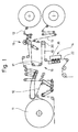
- Fig. 1 shows a film unit as part of a Packaging machine.
- a film web 10 is continuously pulled off a bobbin 11 and guided over a variety of deflection and control rollers.
- a tear strip 12, 13 is in continuous Transport of the film web 10 applied to this and in the area a sealing station 14 also during continuous transport connected to the film web 10 by the application of heat and pressure.
- the unit consisting of film web 10 and tear strip 12, 13 is fed to the packaging machine or a separating unit for cutting off blanks for the outer wrapping.
- a special feature of the device shown in Fig. 1 exists in that it is designed for two-lane operation.
- the film web 10 drawn off from the bobbin 11 has double Width.
- the film web 10 in two side-by-side film webs half width split a middle longitudinal section.
- the two running side by side Foil webs 10 are in the area of a spreading station 16 deflected by spreading rollers 17 so that the two Foil webs 10 are transported parallel at a distance from each other become.
- Each of the film webs 10 is assigned a tear strip 12, 13. These are deducted from separate bobbins. In the area of a union roller 20, the deflecting roller at the same time is 10 for the two film webs, the tear strips 12 and 13 to the assigned, running side by side Foil sheets 10 created.
- Both film webs 10 with tear strips that fit the pack 12, 13 are then the sealing station 14 running side by side fed. There is each film web 10 with tear strips 12, 13 assigned a sealing unit 21. Each of the co-rotating, continuously conveyed film webs 10 is by a sealing unit 21 with the tear strip attached 12, 13 connected. Following the sealing station 14 are therefore two film webs 10 each with a sealed Tear strips 12, 13 transported in parallel and the other Processing fed.
- the tear strips 12, 13 are designed or with a Coating provided that a durable connection with the film web 10 guaranteed when applying heat and pressure.
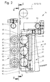
- the sealing unit 21 is designed so that heat and pressure during the continuous transport of the film webs 10 continuously applied to this or to the tear strips 12, 13 become.
- the sealing unit 21 is in the present embodiment in the area of an upright strand 22 of the film webs 10 and tear strips 12, 13 effective.
- the film web act several in the longitudinal direction of the film web 10 successive sealing rolls 23, 24, 25 on film web 10 and tear strips 12, 13 a.
- three sealing rollers 23, 24, 25 on a common, upright Carrier 26 positioned one above the other.
- the sealing rolls 23, 24, 25 are below in the area of the tear strips 12, 13 Transfer of pressure to the tear strips 12, 13 and thus indirectly on the film webs 10.
- Film web 10 are positioned counter pressure elements, namely (Three) counter rollers 27, 28, 29. Also the counter rollers 27..29 are mounted on a common holder 30. The counter rolls 27..29 are positioned exactly opposite the sealing rollers 23..25. Through this film web 10 and tear strips 12, 13th during the conveying movement to the circumference of the counter rollers 27..29 pressed. Sealing rolls 23..25 and counter rolls 27..29 are driven according to the conveying speed of the film web 10, are rotated by this as a result of the conveying movement.
- the sealing rollers 23..25 are heated, so that the Heat is transferred through the sealing rollers 23..25.
- the present exemplary embodiment is indirect heating the sealing rolls 23.25 provided, in particular via Radiant heat.
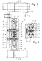
- the carrier 26 is designed as a housing 31 which holds the sealing rollers 23..25 almost completely surrounds, namely up to small areas or openings 32 for the passage of sealing surfaces the sealing rolls 23..25 in the area of the film web 10.
- the housing 31 is heated directly, in the present case Fall through a longitudinally extending heating cartridge 33. This is positioned in a bore 34 which is on the side opposite the film web 10 in the housing 31 directly next to the peripheral surfaces of the sealing rolls 23..25 extends.
- the housing 31 thus heated transmits the Heat on the sealing rolls 23..25.
- the heating element is at the upper end 33 with a connection 35 for electrical lines Mistake.
- the housing 31 for the sealing rollers 23.25 is special Formed such that (radiant) heat from the housing 31 directly onto the film web 10 or the tear strips 12, 13 is transmitted.
- the housing 31 is in the present Case from two parallel longitudinal walls 36, 37 in which the sealing rollers 23..25 with bolts Axes of rotation 38 are mounted.
- a slewing ring 39 of the sealing rollers 23..25 with a Rolling bearing 40 is rotatably supported on the axis of rotation 38.
- the two longitudinal walls 36, 37 are by transverse connecting bolts 41 connected together. These extend in the area of transverse walls 42 of the housing 31. At the ends, that is above and below, the housing 31 is closed by end walls 43.
- the sealing rolls 23..25 are therefore in each case in chambers 44 stored, only to the side, i.e. towards the film web 10, are open (openings 32).
- the housing 31 designed in this way is on the outside of insulating plates 45 surrounded, reduce the heat loss to the outside.
- the insulation panels 45 extend in the region of the longitudinal walls 36, 37 and of the end walls 43.
- the connecting bolts 41 extend through the insulating plates 45 through, so that the unit from the housing 31 and insulating plates 45 held together by the connecting bolts 41 becomes. These also serve to connect the described Unit with the one-arm lever Carrier 26. Accordingly, the housing 31 is attached laterally.
- additional organs for transferring (radiation) heat to the tear strips 12, 13 are arranged.
- the webs 46 are designed so that they are at a distance from the contour of the sealing rollers 23..25 follow and extend a small distance of, for example 1/5 to 1 ⁇ 2 mm distance from the tear strip 12,. 13 This means that additional heat is transferred without contact.
- the sealing rollers 23..25 are designed in a special way. In the area of the outer sealing surface there is an all-round one Siegelsteg 47 formed. This corresponds approximately to the width of the Tear strips 12, 13 or is slightly wider. By this sealing bar 47 receives the slewing ring 39 as an outer area the sealing rollers 23..25 have a T-shaped cross section. This part of the sealing rollers 23..25 consists of a metallic one Material with high thermal conductivity.
- the counter rollers 27..29 only have the task in the present case to generate the required back pressure when sealing.
- the counter rollers 27..29 are also on roller bearings 48 Axle journal 49 mounted. These are laterally with the one-armed Lever trained holder 30 attached.
- the counter rolls 27..29 have one in relation to the sealing rolls 23..25 wider outer contact or outer surface. at the exemplary embodiment shown is the outer circumference of the counter rollers 27..29 elastic. 5, is for this purpose on the counter rollers 27..29 Jacket 50 made of elastic material attached, in particular Silicone.
- the film web 10 is accordingly by the sealing rolls 23, 24 pressed against the elastic jacket 50. This one has as shown, a spherical outer contact surface 51 here.
- the sealing rolls 23..25 and / or the counter rolls 27..29 are adjustable.
- the carrier is 26 on the one hand and the holder 30 on the other hand movably arranged.
- the angularly shaped support 26 is on a fixed Support pin 52 rotatably mounted.
- the holder 30 for the counter rollers 27..29 is on one side a holding pin 53 rotatably mounted. Through this storage can the relative position of the holder 30 with the counter rollers 27..29 can be set.
Description
Die Erfindung betrifft eine Vorrichtung zum Verbinden eines fortlaufend zugeführten Materialstreifens, insbesondere eines Aufreißstreifens, mit einer fortlaufend geförderten Materialbahn, insbesondere einer Folienbahn, zum Herstellen von Zuschnitten für Packungsumhüllungen mit Aufreißstreifen, wobei der Materialstreifen durch beheizte, nach Maßgabe der Förderbewegung der Materialbahn und des Materialstreifens drehende Druck- und Siegelorgane an die Materialbahn andrückbar und mit dieser verbindbar ist und wobei als Druck- und Siegelorgan eine beheizte Siegelrolle vorgesehen ist.The invention relates to a device for connecting a continuously supplied Material strip, in particular a tear strip, with a continuously conveyed Material web, in particular a film web, for producing blanks for Pack wrappings with tear strips, the material strip being heated by according to the conveying movement of the material web and the material strip rotating pressure and sealing elements can be pressed onto the material web and with it is connectable and a heated sealing roller is provided as the pressure and sealing element is.
Verpackungen sind vielfach mit einer Außenumhüllung aus dünner Kunststofffolie oder Zellglasfolie versehen. Diese wird bei Ingebrauchnahme der Verpackung mit Hilfe eines Aufreißstreifens entfernt. Insbesondere sind Zigarettenpackungen mit einer durch einen ringsherum laufenden Aufreißstreifen zerstörbaren Umhüllung versehen.Packaging is often with an outer wrapping made of thin plastic film or Provide cellophane film. This is checked when using the packaging with the help of a Tear strip removed. In particular, cigarette packs are one by one Provide destructible wrapping all around.
Der Aufreißstreifen wird üblicherweise fortlaufend auf die ebenfalls fortlaufende Folienbahn aufgebracht und mit dieser durch Kleben oder thermisches Siegeln verbunden. Bei dem letztgenannten Verfahren ist der Aufreißstreifen mit einem durch Wärme und Druck aktivierbaren Kleber versehen. Die Verbindung des Aufreißstreifens mit der Folienbahn ist dadurch zeitaufwendig und erfordert besondere apparative Einrichtungen.The tear strip is usually continuous on the also continuous Foil sheet applied and with this by gluing or thermal sealing connected. In the latter method, the tear strip is through with one Provide heat and pressure activatable adhesive. The connection of the tear strip with the film web is therefore time-consuming and requires special equipment Institutions.
Aus der DE-A-38 21 266 ist eine Vorrichtung für die Anbringung eines Aufreißstreifens an einem endlosen Band aus Umhüllungsmaterial bekannt, wobei die Verschweißung des Streifens und des Bandes während des Laufes derselben um eine Umlenkwalze erfolgt, die mittels Heizeinrichtungen geheizt wird. Aufgrund der Umlenkung von Aufreißstreifen und Band um die genannte Umlenkwalze kommt es zu Materialverschiebungen während des Verklebens.DE-A-38 21 266 discloses a device for attaching a tear strip an endless band of wrapping material known, the welding of the Strip and the tape while running the same around a deflection roller, which is heated by means of heating devices. Due to the deflection of tear strips and belt around said guide roller, material shifts occur during of sticking.
Die GB 961 805 zeigt eine Vorrichtung zum Heißsiegeln von entsprechender Folie oder beschichtetem Papier. Das Aufbringen eines Materialstreifens ist nicht gezeigt. Erkennbar sind vier Rollenpaare, zwischen denen eine Materialbahn hindurchgeführt und dabei gesiegelt wird. Die Rollenpaare sind an Siegelbacken gehalten, sodass die Rollen mit ihren Durchmessern durch eine unterbrochene Oberfläche von Siegelleisten hindurchtreten.GB 961 805 shows a device for heat sealing the corresponding film or coated paper. The application of a strip of material is not shown. recognizable are four pairs of rollers, between which a material web is passed and there is sealed. The roller pairs are held on sealing jaws, so that the rollers with their diameters through an interrupted surface of sealing strips pass.
Der Erfindung liegt die Aufgabe zugrunde, das Anbringen eines Materialstreifens, insbesondere eines Aufreißstreifens, an einer Folienbahn unter Aufwendung von Wärme und Druck zu verbessern, dahingehend, dass die Verbindung auch bei höheren Arbeitsgeschwindigkeiten zuverlässig erfolgt, und dass insbesondere zusätzlich Wärme auf die Siegelrollen und auf das zu verbindende Material übertragen wird.The invention has for its object the application of a strip of material, in particular a tear strip, on a film web using heat and to improve pressure in that connection even at higher Working speeds are reliable, and in particular that additional heat is transferred to the sealing rolls and to the material to be connected.
Zur Lösung dieser Aufgabe ist die erfindungsgemäße Vorrichtung dadurch gekennzeichnet, dass mehrere Siegelrollen in Förderrichtung aufeinanderfolgend angeordnet und überwiegend oder ausschließlich indirekt beheizt sind, dass im Bereich zwischen den aufeinanderfolgenden Siegelrollen und mit geringem Abstand zur Materialbahn bzw. zum Materialstreifen Wärmeübertragungsorgane, nämlich beheizte Stege angeordnet sind, dass die Stege dünnwandig sind und sich in Längsrichtung des Materialstreifens erstrecken, und dass die Stege mit Abstand der Kontur der in Förderrichtung aufeinanderfolgend angeordneten Siegelrollen folgen. To achieve this object, the device according to the invention is thereby characterized that several sealing rolls in the conveying direction successively arranged and predominantly or exclusively indirectly heated that in the area between the successive sealing rolls and at a short distance from the Material web or to the material strip heat transfer elements, namely heated Are arranged that the webs are thin-walled and in the longitudinal direction of the Stretch material strip, and that the webs at a distance from the contour of the Follow the direction of conveyance of successively arranged sealing rolls.
Bei der erfindungsgemäßen Vorrichtung werden demnach die miteinander zu verbindenden Materialien, nämlich die Folienbahn und der auf dieser positionsgerecht angeordnete Aufreißstreifen fortlaufend zwischen Druckrollen und Gegendruckrollen hindurchgefördert, wobei mindestens die Druckrollen beheizt sind.In the device according to the invention, they are accordingly materials to be joined, namely the film web and the tear strip arranged on it in the correct position conveyed continuously between pressure rollers and counter pressure rollers, at least the pressure rollers are heated.
Bei einer vorteilhaften Ausführungsform der Erfindung sind in Förderrichtung der Materialbahn aufeinanderfolgend drei indirekt beheizte Druckrollen positioniert und auf der gegenüberliegenden Seite derselben drei Gegendruckrollen.In an advantageous embodiment of the invention are in Direction of conveyance of the material web successively three indirectly heated pressure rollers positioned and on the opposite Side of the same three counter pressure rollers.
Mit Hitfe der Erfindung wird zusätzlich (Strahlungs-)Wärme auf die Siegelrollen und zusätzlich auf das zu verbindende Material, also Aufreißstreifen und Materialbahn, durch die Stege übertragen .With Hitfe the invention is additional (Radiant) heat on the sealing rolls and additionally on the material to be connected, i.e. tear strips and material web, transmitted through the webs.
Bevorzugte Ausführungsformen der Erfindung sind Gegenstand der Patentansprüche und werden nachfolgend anhand eines in den Zeichnungen dargestellten Ausführungsbeispiels näher beschrieben. Es zeigt:
- Fig. 1
- eine Einrichtung zum Verbinden einer Folienbahn mit einem Aufreißstreifen in schematischer Seitenansicht,
- Fig. 2
- eine Verbindungsstation von Aufreißstreifen und Folienbahn, ebenfalls in Seitenansicht, bei vergrößertem Maßstab,
- Fig. 3
- eine Einzelheit der Vorrichtung gemäß Fig. 2 in nochmals vergrößertem Maßstab, teilweise im Vertikalschnitt,
- Fig. 4
- eine einzelne Druck- bzw. Siegelrolle im Radialschnitt, nochmals vergrößert,
- Fig. 5
- eine Halterung mit Gegendruckrollen in Seitenansicht.
- Fig. 1
- a device for connecting a film web with a tear strip in a schematic side view,
- Fig. 2
- a connection station of tear strip and film web, also in side view, on an enlarged scale,
- Fig. 3
- 2 on a further enlarged scale, partly in vertical section,
- Fig. 4
- a single pressure or sealing roll in radial section, enlarged again,
- Fig. 5
- a bracket with counter pressure rollers in side view.
Das vorliegende Ausführungsbeispiel ist besonders geeignet im Zusammenhang mit der Fertigung von Zigarettenpackungen mit einer Außenumhüllung aus Zellglas oder Kunststoffolie mit einem Aufreißstreifen. Fig. 1 zeigt ein Folienaggregat als Teil einer Verpackungsmaschine.The present embodiment is particularly suitable in Connection with the manufacture of cigarette packs with an outer covering made of cellophane or plastic film with a Tear. Fig. 1 shows a film unit as part of a Packaging machine.
Eine Folienbahn 10 wird fortlaufend von einer Bobine 11 abgezogen
und über eine Vielzahl von Umlenk- und Steuerwalzen geführt.
Ein Aufreißstreifen 12, 13 wird bei kontinuierlichem
Transport der Folienbahn 10 an diese angelegt und im Bereich
einer Siegelstation 14 ebenfalls bei fortlaufendem Transport
mit der Folienbahn 10 durch Aufwendung von Wärme und Druck verbunden.
Die Einheit aus Folienbahn 10 und Aufreißstreifen 12,
13 wird der Verpackungsmaschine zugeführt bzw. einem Trennaggregat
zum Abtrennen von Zuschnitten für die Außenumhüllung.A
Eine Besonderheit der in Fig. 1 gezeigten Einrichtung besteht
darin, daß diese für zweibahnige Betriebsweise ausgelegt ist.
Die von der Bobine 11 abgezogene Folienbahn 10 hat doppelte
Breite. Im Bereich einer Trennstation 15 wird die Folienbahn 10
in zwei nebeneinanderlaufende Folienbahnen halber Breite durch
einen mittleren Längsschnitt aufgeteilt. Die beiden nebeneinanderlaufenden
Folienbahnen 10 werden im Bereich einer Spreizstation
16 durch Spreizrollen 17 so umgelenkt, daß die beiden
Folienbahnen 10 in einem Abstand voneinander parallel weitertransportiert
werden.A special feature of the device shown in Fig. 1 exists
in that it is designed for two-lane operation.
The
Jeder der Folienbahnen 10 ist ein Aufreißstreifen 12, 13 zugeordnet.
Diese werden von gesonderten Bobinen abgezogen.
Im Bereich einer Vereinigungswalze 20, die zugleich Umlenkwalze
für die beiden Folienbahnen 10 ist, werden die Aufreißstreifen
12 und 13 an die zugeordneten, nebeneinanderlaufenden
Folienbahnen 10 angelegt.Each of the
Beide Folienbahnen 10 mit packungsgerecht anliegenden Aufreißstreifen
12, 13 werden sodann der Siegelstation 14 nebeneinanderlaufend
zugeführt. Dort ist jeder Folienbahn 10 mit Aufreißstreifen
12, 13 ein Siegelaggregat 21 zugeordnet. Jede der
gleichlaufenden, kontinuierlich geförderten Folienbahnen 10
wird durch ein Siegelaggregat 21 mit dem anliegenden Aufreißstreifen
12, 13 verbunden. Im Anschluß an die Siegelstation 14
werden demnach zwei Folienbahnen 10 mit je einem angesiegelten
Aufreißstreifen 12, 13 parallel transportiert und der weiteren
Verarbeitung zugeführt.Both
Die Aufreißstreifen 12, 13 sind so ausgebildet bzw. mit einer
Beschichtung versehen, die eine haltbare Verbindung mit der Folienbahn
10 bei Aufbringen von Wärme und Druck gewährleistet.
Das Siegelaggregat 21 ist so ausgebildet, daß Wärme und Druck
während des kontinuierlichen Transports der Folienbahnen 10
fortlaufend auf diese bzw. auf die Aufreißstreifen 12, 13 aufgebracht
werden.The
Das Siegelaggregat 21 wird bei dem vorliegenden Ausführungsbeispiel
im Bereich eines aufrechten Strangs 22 der Folienbahnen
10 und Aufreißstreifen 12, 13 wirksam. In Förderrichtung
der Folienbahn wirken mehrere in Längsrichtung der Folienbahn
10 aufeinanderfolgende Siegelrollen 23, 24, 25 auf Folienbahn
10 und Aufreißstreifen 12, 13 ein. Im vorliegenden Falle sind
drei Siegelrollen 23, 24, 25 an einem gemeinsamen, aufrechten
Träger 26 übereinanderliegend positioniert. Die Siegelrollen
23, 24, 25 liegen im Bereich der Aufreißstreifen 12, 13 unter
Übertragung von Druck an den Aufreißstreifen 12, 13 und damit
indirekt an den Folienbahnen 10 an. The
Auf der zu den Siegelrollen 23..25 gegenüberliegenden Seite der
Folienbahn 10 sind Gegendruckorgane positioniert, nämlich
(drei) Gegenrollen 27, 28, 29. Auch die Gegenrollen 27..29 sind
an einem gemeinsamen Halter 30 gelagert. Die Gegenrollen 27..29
sind jeweils exakt gegenüber den Siegelrollen 23..25 gelagert.
Durch diese werden Folienbahn 10 und Aufreißstreifen 12, 13
während der Förderbewegung an den Umfang der Gegenrollen 27..29
angedrückt. Siegelrollen 23..25 und Gegenrollen 27..29 sind
entsprechend der Fördergeschwindigkeit der Folienbahn 10 angetrieben,
werden durch diese infolge der Förderbewegung gedreht.On the side of the opposite to the
Die Siegelrollen 23..25 sind beheizt, so daß zum Druck auch die
Wärme durch die Siegelrollen 23..25 übertragen wird. Bei dem
vorliegenden Ausführungsbeispiel ist eine indirekte Beheizung
der Siegelrollen 23..25 vorgesehen, und zwar insbesondere über
Strahlungswärme.The sealing
Der Träger 26 ist als Gehäuse 31 ausgebildet, welches die Siegelrollen
23..25 nahezu vollständig umgibt, nämlich bis auf
kleine Bereiche bzw. Öffnungen 32 für den Durchtritt von Siegelflächen
der Siegelrollen 23..25 im Bereich der Folienbahn
10. Das Gehäuse 31 ist unmittelbar beheizt, im vorliegenden
Fall durch eine sich in Längsrichtung erstreckende Heizpatrone
33. Diese ist in einer Bohrung 34 positioniert, die sich auf
der zur Folienbahn 10 gegenüberliegenden Seite im Gehäuse 31
unmittelbar neben den Umfangsflächen der Siegelrollen 23..25
erstreckt. Das hierdurch beheizte Gehäuse 31 überträgt die
Wärme auf die Siegelrollen 23..25. Am oberen Ende ist die Heizpatrone
33 mit einem Anschluß 35 für elektrische Leitungen
versehen.The
Das Gehäuse 31 für die Siegelrollen 23..25 ist in besonderer
Weise ausgebildet, derart, daß (Strahlungs-)Wärme von dem Gehäuse
31 unmittelbar auf die Folienbahn 10 bzw. die Aufreißstreifen
12, 13 übertragen wird. Das Gehäuse 31 besteht im vorliegenden
Fall aus zwei parallelen Längswänden 36, 37, in denen
die Siegelrollen 23..25 mit als Schraubenbolzen ausgebildeten
Drehachsen 38 gelagert sind. Wie insbesondere in Fig. 3 und 4
gezeigt, ist ein Drehkranz 39 der Siegelrollen 23..25 mit einem
Wälzlager 40 drehbar auf der Drehachse 38 gelagert. The
Die beiden Längswände 36, 37 sind durch quergerichtete Verbindungsbolzen
41 miteinander verbunden. Diese erstrecken sich im-Bereich
von Querwänden 42 des Gehäuses 31. An den Enden, also
oben und unten, ist das Gehäuse 31 durch Endwände 43 geschlossen.
Die Siegelrollen 23..25 sind demnach jeweils in Kammern 44
gelagert, die lediglich zur Seite, also in Richtung zur Folienbahn
10, offen sind (Öffnungen 32).The two
Das so ausgebildete Gehäuse 31 ist außen von Isolierplatten 45
umgeben, die Wärmeverluste nach außen reduzieren. Die Isolierplatten
45 erstrecken sich im Bereich der Längswände 36, 37 und
der Endwände 43. Die Verbindungsbolzen 41 erstrecken sich durch
die Isolierplatten 45 hindurch, so daß die Einheit aus Gehäuse
31 und Isolierplatten 45 durch die Verbindungsbolzen 41 zusammengehalten
wird. Diese dienen zugleich zur Verbindung der beschriebenen
Einheit mit dem als einarmiger Hebel ausgebildeten
Träger 26. An diesem ist das Gehäuse 31 demnach seitlich angebracht.The
Zwischen den Siegelrollen 23..25 sind auf der der Folienbahn 10
zugekehrten Seite am Gehäuse 31 zusätzliche Organe zur Übertragung
von (Strahlungs-)Wärme auf die Aufreißstreifen 12, 13 angeordnet.
Es handelt sich dabei um Stege 46, die als verhältnismäßig
dünnwandige Organe exakt im Bereich der Aufreißstreifen
12, 13 am Gehäuse angebracht sind, nämlich an den Querwänden
42 und den Endwänden 43. Die Stege 46 sind so ausgebildet,
daß sie mit Abstand der Kontur der Siegelrollen 23..25 folgen
und mit geringem Abstand von beispielsweise 1/5 bis ½ mm Abstand
von dem Aufreißstreifen 12, 13 verlaufen. Dadurch wird
berührungslos zusätzlich Wärme übertragen.Between the sealing rolls 23. 25, on the side facing the
In besonderer Weise sind die Siegelrollen 23..25 ausgebildet.
Im Bereich der äußeren Siegelfläche ist ein ringsherumlaufender
Siegelsteg 47 gebildet. Dieser entspricht etwa der Breite der
Aufreißstreifen 12, 13 bzw. ist geringfügig breiter. Durch
diesen Siegelsteg 47 erhält der Drehkranz 39 als äußerer Bereich
der Siegelrollen 23..25 einen T-förmigen Querschnitt.
Dieser Teil der Siegelrollen 23..25 besteht aus einem metallischen
Werkstoff mit hoher Wärmeleitfähigkeit. The sealing
Die Gegenrollen 27..29 haben im vorliegenden Falle nur die Aufgabe,
den erforderlichen Gegendruck beim Siegeln zu erzeugen.
Die Gegenrollen 27..29 sind ebenfalls mit Wälzlagern 48 auf
Achszapfen 49 gelagert. Diese sind seitlich mit dem als einarmiger
Hebel ausgebildeten Halter 30 befestigt.The
Die Gegenrollen 27..29 haben eine im Verhältnis zu den Siegelrollen
23..25 breitere äußere Anlage- bzw. Mantelfläche. Bei
dem gezeigten Ausführungsbeispiel ist der Außenumfang der Gegenrollen
27..29 elastisch ausgebildet. Wie aus Fig. 5 ersichtlich,
ist zu diesem Zweck auf den Gegenrollen 27..29 ein
Mantel 50 aus elastischem Werkstoff befestigt, insbesondere aus
Silikon. Die Folienbahn 10 wird demnach durch die Siegelrollen
23, 24 gegen den elastischen Mantel 50 gedrückt. Dieser hat,
wie gezeigt, hier eine ballige äußere Anlagefläche 51.The counter rolls 27..29 have one in relation to the sealing rolls
23..25 wider outer contact or outer surface. at
the exemplary embodiment shown is the outer circumference of the
Die Siegelrollen 23..25 und/oder die Gegenrollen 27..29 sind
verstellbar gelagert. Im vorliegenden Falle sind der Träger 26
einerseits und der Halter 30 andererseits bewegbar angeordnet.
Der winkelförmig ausgebildete Träger 26 ist auf einem feststehenden
Tragzapfen 52 drehbar gelagert. Bei Betriebsunterbrechung
wird das Siegelaggregat 21 bzw. der Träger 26 mit den
Siegelrollen 23..25 außer Anlage an den Folienbahnen 10 bewegt,
nämlich durch Verschwenken in die in Fig. 2 strichpunktiert
gezeichnete Position.The sealing rolls 23..25 and / or the counter rolls 27..29 are
adjustable. In the present case, the carrier is 26
on the one hand and the
Auch der Halter 30 für die Gegenrollen 27..29 ist einseitig auf
einem Haltezapfen 53 drehbar gelagert. Durch diese Lagerung
kann die Relativstellung des Halters 30 mit den Gegenrollen
27..29 eingestellt werden.The
Claims (11)
- Apparatus for joining a continuously supplied material strip (12, 13), in particular a tearstrip, to a continuously conveyed material web (10), in particular a film web, for producing blanks for pack wrappers with tearstrips, it being possible for the material strip (12, 13) to be pressed onto the material web (10) by heated pressing and sealing elements that rotate on the basis of the conveying movement of the material web (10) and of the material strip and to be joined to the said web, a heated sealing roller being provided as the pressing and sealing element, characterized in that a plurality of sealing rollers (23, 24, 25) are arranged to follow one another in the conveying direction and are predominently or exclusively heated indirectly, in that, in the region between the successive sealing rollers (23, 24, 25) and at a short distance from the material web (10) and the material strip (12, 13), heat transfer elements, specifically heated webs (46) are arranged, in that the webs (46) are thin-walled and extend in the longitudinal direction of the material strip (12, 13), and in that the webs (46) follow at a distance the contour of the sealing rollers (23, 24, 25) arranged to follow one another in the conveying direction.
- Apparatus according to Claim 1, characterized in that the webs (46) consist of heat-conducting material.
- Apparatus according to Claim 1 or 2, characterized in that the sealing rollers (23, 24, 25) are mounted in a housing (31) made of a material of high thermal conductivity, the housing being heated, preferably by means of at least one heating cartridge (33) arranged in the housing (31).
- Apparatus according to Claim 1 or one of the further claims, characterized in that the webs (46) are arranged on a housing (31) and are heated by the latter or a heating cartridge (33) arranged in the housing (31).
- Apparatus according to Claim 1 or one of the further claims, characterized in that in the conveying direction of the material web (10) and of the material strip (12, 13) a plurality of pairs of mutually opposite sealing rollers (23, 24, 25) and backing rollers (27, 28, 29) are arranged, in particular three pairs of sealing rollers (23, 24, 25) and backing rollers (27, 28, 29) of preferably approximately equal size.
- Apparatus according to Claim 1 or one of the further claims, characterized in that the sealing rollers (23, 24, 25) have a (T-shaped) profile with a narrow outer sealing web (47) running all around to make contact with the material strip (12, 13), in particular the sealing web (47) being part of an outer ring mount (39) of the sealing rollers (23, 24, 25) and consisting of heat-conducting material.
- Apparatus according to Claim 1 or one of the further claims, characterized in that the backing rollers (27, 28, 29), wholly or partly, specifically at least in the region of an outer cover (50), consist of elastically compressible material, preferably of silicone.
- Apparatus according to Claim 7 or one of the further claims, characterized in that the backing rollers (27, 28, 29) have an outer contact face for the material web (10), which has a greater width than sealing faces of the sealing rollers (23, 24, 25), in particular than the sealing web (47) of the same.
- Apparatus according to Claim 1 or one of the further claims, characterized in that the sealing rollers (23..25) and the housing (31) are fitted to a carrier (26), which is mounted such that it can be adjusted, in particular as a pivotable, single-armed lever.
- Apparatus according to Claim 1 or one of the further claims, characterized in that the backing rollers (27, 28, 29) are fitted to a holder (30) which can be adjusted relative to the sealing rollers (23, 24, 25).
- Apparatus according to Claim 1 or one of the further claims, characterized in that the sealing rollers (23, 24, 25) and backing rollers (27, 28, 29) act in the region of an upright conveying section, specifically an upright strand (22) of the material web (10).
Applications Claiming Priority (2)
| Application Number | Priority Date | Filing Date | Title |
|---|---|---|---|
| DE19619558A DE19619558A1 (en) | 1996-05-14 | 1996-05-14 | Device for connecting a tear strip with a film web |
| DE19619558 | 1996-05-14 |
Publications (2)
| Publication Number | Publication Date |
|---|---|
| EP0807513A1 EP0807513A1 (en) | 1997-11-19 |
| EP0807513B1 true EP0807513B1 (en) | 2002-07-24 |
Family
ID=7794370
Family Applications (1)
| Application Number | Title | Priority Date | Filing Date |
|---|---|---|---|
| EP97107430A Expired - Lifetime EP0807513B1 (en) | 1996-05-14 | 1997-05-06 | Apparatus for joining a tearstrip to a film |
Country Status (5)
| Country | Link |
|---|---|
| US (1) | US5858167A (en) |
| EP (1) | EP0807513B1 (en) |
| JP (1) | JP3790012B2 (en) |
| CN (1) | CN1105064C (en) |
| DE (2) | DE19619558A1 (en) |
Families Citing this family (6)
| Publication number | Priority date | Publication date | Assignee | Title |
|---|---|---|---|---|
| DE19702473A1 (en) * | 1997-01-24 | 1998-07-30 | Kraemer & Grebe Kg | Method and device for sealing film webs |
| DE10034910C2 (en) * | 2000-07-18 | 2002-08-14 | Windmoeller & Hoelscher | Heat sealing device |
| EP1209083B1 (en) | 2000-11-24 | 2004-08-18 | Focke & Co. (GmbH & Co.) | Method and device for manufacturing wrapped packages and bobine |
| US6889483B2 (en) | 2002-10-31 | 2005-05-10 | Cryovac, Inc. | Easy-opening feature for flexible packages and process and apparatus for forming same |
| US7591294B2 (en) * | 2007-11-29 | 2009-09-22 | Spirit Aerosystems, Inc. | Material placement method and apparatus |
| CN105000229B (en) * | 2015-07-08 | 2017-07-04 | 北京洋航科贸有限公司 | For the device being sealed and welded in easy tear tape on package body |
Family Cites Families (28)
| Publication number | Priority date | Publication date | Assignee | Title |
|---|---|---|---|---|
| DE7340444U (en) * | 1975-07-31 | Windmoeller & Hoelscher | Device for welding reinforcement labels onto a plastic film web | |
| DE819497C (en) * | 1941-12-23 | 1951-10-31 | Fischer & Krecke G M B H | Device for hot bonding the longitudinal seams of cellulose film or plastic film workpieces |
| US2451728A (en) * | 1945-04-17 | 1948-10-19 | Breslee Mfg Company | Heat-sealing apparatus |
| US2660219A (en) * | 1950-03-15 | 1953-11-24 | Interstate Folding Box Co | Heat-sealing machine |
| US2845213A (en) * | 1953-06-10 | 1958-07-29 | Bernard J Tamarin | Package with tear tab opening means |
| DE1157765B (en) * | 1959-09-24 | 1963-11-21 | Darex A G | Sealing roll with electrical heating wires for sealing thermoplastic plastic films |
| US3218961A (en) * | 1961-02-10 | 1965-11-23 | Phillips Petroleum Co | Thermoplastic bag sealer |
| US3059690A (en) * | 1961-07-05 | 1962-10-23 | Ralph A Nyborg | Heat sealing apparatus |
| GB961805A (en) * | 1963-01-26 | 1964-06-24 | Holstein & Kappert Maschf | An apparatus for heat sealing papers or the like coated with plastics material |
| AT245492B (en) * | 1963-08-17 | 1966-02-25 | Hamac Hansella Ag | Device for applying the longitudinal weld seam or seams to the wrapping material web or sheets in tubular bag packaging machines |
| DE1511626A1 (en) * | 1965-07-19 | 1969-09-11 | Hauni Werke Koerber & Co Kg | Device in packing machines for connecting parts of the wrapping of cigarette packs or other block-shaped objects |
| US3484325A (en) * | 1966-07-13 | 1969-12-16 | John M Pendleton | Apparatus for sealing thermoplastic films |
| US3804697A (en) * | 1969-11-24 | 1974-04-16 | Schjeldahl Co G T | Moveable heat sealing apparatus |
| DE2237877C3 (en) * | 1972-08-02 | 1979-01-11 | Packautomatic Gmbh & Co Kg, 5828 Ennepetal | Device for welding the laterally protruding ends of a tubular film envelope containing a package |
| US4270965A (en) * | 1976-10-06 | 1981-06-02 | Torterotot Roland | Production of sterile packages |
| US4067761A (en) * | 1976-12-20 | 1978-01-10 | The Kartridg Pak Co. | Plastic web sealing apparatus using hot air heated sealing roller |
| JPS55123411U (en) * | 1979-02-23 | 1980-09-02 | ||
| US4288967A (en) * | 1979-11-30 | 1981-09-15 | Fuji Machinery Co. Ltd. | Center sealing device for a plastic film in a packaging apparatus |
| DE3542256A1 (en) * | 1985-11-29 | 1987-06-04 | Hoechst Ag | DEVICE FOR CONTINUOUS WELDING OR SEALING SEAMS OF PLASTIC FILMS |
| US4666550A (en) * | 1986-02-24 | 1987-05-19 | Philip Morris Incorporated | Apparatus for producing a strip of laminated sheet material |
| US4721501A (en) * | 1986-09-08 | 1988-01-26 | Mobil Oil Corporation | Apparatus for producing a machine-direction heat seal |
| US4717372A (en) * | 1986-12-08 | 1988-01-05 | Mobil Oil Corporation | Apparatus for producing a machine-direction intermittent heat seal |
| IT1207736B (en) * | 1987-06-25 | 1989-05-25 | Gd Spa | DEVICE FOR THE APPLICATION OF A TEAR TAPE ON A CONTINUOUS TAPE OF WRAPPING MATERIAL |
| US4808150A (en) * | 1987-09-25 | 1989-02-28 | Mobil Oil Corporation | Oven-heated hot wheel sealing apparatus |
| JPH02258509A (en) * | 1989-03-28 | 1990-10-19 | Chuo Housouki Kk | Excessive part cutting off device for packaging bag fastened edge in filling and packaging machine |
| DE9012482U1 (en) * | 1990-08-31 | 1990-11-08 | Rovema - Verpackungsmaschinen Gmbh, 6301 Fernwald, De | |
| DE4215690A1 (en) * | 1992-05-14 | 1993-11-18 | Focke & Co | Device for connecting a tear strip to a material web |
| JPH0891330A (en) * | 1994-09-21 | 1996-04-09 | Shikoku Kakoki Co Ltd | Sticking device for seal tape |
-
1996
- 1996-05-14 DE DE19619558A patent/DE19619558A1/en not_active Withdrawn
-
1997
- 1997-05-06 DE DE59707766T patent/DE59707766D1/en not_active Expired - Lifetime
- 1997-05-06 EP EP97107430A patent/EP0807513B1/en not_active Expired - Lifetime
- 1997-05-13 US US08/855,541 patent/US5858167A/en not_active Expired - Fee Related
- 1997-05-14 JP JP12441497A patent/JP3790012B2/en not_active Expired - Fee Related
- 1997-05-14 CN CN97111549A patent/CN1105064C/en not_active Expired - Fee Related
Also Published As
| Publication number | Publication date |
|---|---|
| JPH1086916A (en) | 1998-04-07 |
| JP3790012B2 (en) | 2006-06-28 |
| CN1169388A (en) | 1998-01-07 |
| DE59707766D1 (en) | 2002-08-29 |
| US5858167A (en) | 1999-01-12 |
| EP0807513A1 (en) | 1997-11-19 |
| CN1105064C (en) | 2003-04-09 |
| DE19619558A1 (en) | 1997-11-20 |
Similar Documents
| Publication | Publication Date | Title |
|---|---|---|
| DE3142202C2 (en) | ||
| EP1751005B1 (en) | Method and device for packaging flat articles | |
| DE3416721C2 (en) | Device for winding a web | |
| DE3039293A1 (en) | DEVICE FOR FEEDING A WRAPPING SHEET TO A LARGE PAPER ROLL OR THE LIKE. | |
| EP1044882A1 (en) | Device for packaging a roll of web material | |
| DE4215690A1 (en) | Device for connecting a tear strip to a material web | |
| EP0807513B1 (en) | Apparatus for joining a tearstrip to a film | |
| DE1586093A1 (en) | Device for applying tear strips to a wrapping material strip | |
| WO2016124313A1 (en) | Apparatus and method for producing rectangular packs for cigarettes | |
| DE4340039C2 (en) | Coating device for running webs of paper or cardboard | |
| DE3002092C2 (en) | Device for feeding tape-shaped packaging material | |
| WO1996026829A1 (en) | Process and device for heating a moving web, in particular a corrugated cardboard web | |
| DE2914696C2 (en) | Device for applying rider tapes provided with an adhesive to the flat front edges of hose sections or sacks | |
| EP0014858B1 (en) | Method and device for attaching tear strips or the like to a web of wrapping material | |
| DE1285856B (en) | Device for applying adhesive when sticking tear strips onto a packaging strip | |
| DE3821266A1 (en) | Apparatus for attaching a tear-open strip | |
| DE1252521B (en) | Corrugating machine | |
| DE19983258B4 (en) | Apparatus and method for laminating paper | |
| EP0972707A1 (en) | Method and apparatus for packaging a roll of web material | |
| EP0849179A1 (en) | Device for packaging a roll of web material by means of packaging web | |
| DE19546697A1 (en) | Packing-material-sheet conveyor to cigarette-packing machine | |
| EP0406988B1 (en) | Embossing rollers | |
| EP0719228A1 (en) | Method and device for packaging profiles | |
| EP0873940B1 (en) | Roll cutting device with a packaging means | |
| DE102005005215B3 (en) | Window welding-in process for folding box cutouts involves feeding cutouts with foil pieces to conveyor belt and putting them in gap between diverting drum and belt |
Legal Events
| Date | Code | Title | Description |
|---|---|---|---|
| PUAI | Public reference made under article 153(3) epc to a published international application that has entered the european phase |
Free format text: ORIGINAL CODE: 0009012 |
|
| AK | Designated contracting states |
Kind code of ref document: A1 Designated state(s): CH DE GB IT LI |
|
| 17P | Request for examination filed |
Effective date: 19971227 |
|
| 17Q | First examination report despatched |
Effective date: 19990526 |
|
| GRAG | Despatch of communication of intention to grant |
Free format text: ORIGINAL CODE: EPIDOS AGRA |
|
| GRAG | Despatch of communication of intention to grant |
Free format text: ORIGINAL CODE: EPIDOS AGRA |
|
| GRAH | Despatch of communication of intention to grant a patent |
Free format text: ORIGINAL CODE: EPIDOS IGRA |
|
| GRAH | Despatch of communication of intention to grant a patent |
Free format text: ORIGINAL CODE: EPIDOS IGRA |
|
| GRAA | (expected) grant |
Free format text: ORIGINAL CODE: 0009210 |
|
| AK | Designated contracting states |
Kind code of ref document: B1 Designated state(s): CH DE GB IT LI |
|
| REG | Reference to a national code |
Ref country code: GB Ref legal event code: FG4D Free format text: NOT ENGLISH |
|
| REG | Reference to a national code |
Ref country code: CH Ref legal event code: EP |
|
| GBT | Gb: translation of ep patent filed (gb section 77(6)(a)/1977) |
Effective date: 20020724 |
|
| REG | Reference to a national code |
Ref country code: CH Ref legal event code: NV Representative=s name: DIPL.-ING. ETH H. R. WERFFELI PATENTANWALT |
|
| REF | Corresponds to: |
Ref document number: 59707766 Country of ref document: DE Date of ref document: 20020829 |
|
| PLBE | No opposition filed within time limit |
Free format text: ORIGINAL CODE: 0009261 |
|
| STAA | Information on the status of an ep patent application or granted ep patent |
Free format text: STATUS: NO OPPOSITION FILED WITHIN TIME LIMIT |
|
| 26N | No opposition filed |
Effective date: 20030425 |
|
| PGFP | Annual fee paid to national office [announced via postgrant information from national office to epo] |
Ref country code: CH Payment date: 20060515 Year of fee payment: 10 |
|
| REG | Reference to a national code |
Ref country code: CH Ref legal event code: PL |
|
| PG25 | Lapsed in a contracting state [announced via postgrant information from national office to epo] |
Ref country code: CH Free format text: LAPSE BECAUSE OF NON-PAYMENT OF DUE FEES Effective date: 20070531 Ref country code: LI Free format text: LAPSE BECAUSE OF NON-PAYMENT OF DUE FEES Effective date: 20070531 |
|
| PGFP | Annual fee paid to national office [announced via postgrant information from national office to epo] |
Ref country code: IT Payment date: 20090516 Year of fee payment: 13 |
|
| PGFP | Annual fee paid to national office [announced via postgrant information from national office to epo] |
Ref country code: GB Payment date: 20090506 Year of fee payment: 13 |
|
| GBPC | Gb: european patent ceased through non-payment of renewal fee |
Effective date: 20100506 |
|
| PG25 | Lapsed in a contracting state [announced via postgrant information from national office to epo] |
Ref country code: IT Free format text: LAPSE BECAUSE OF NON-PAYMENT OF DUE FEES Effective date: 20100506 |
|
| PG25 | Lapsed in a contracting state [announced via postgrant information from national office to epo] |
Ref country code: GB Free format text: LAPSE BECAUSE OF NON-PAYMENT OF DUE FEES Effective date: 20100506 |
|
| PGFP | Annual fee paid to national office [announced via postgrant information from national office to epo] |
Ref country code: DE Payment date: 20130527 Year of fee payment: 17 |
|
| REG | Reference to a national code |
Ref country code: DE Ref legal event code: R119 Ref document number: 59707766 Country of ref document: DE |
|
| REG | Reference to a national code |
Ref country code: DE Ref legal event code: R119 Ref document number: 59707766 Country of ref document: DE Effective date: 20141202 |
|
| PG25 | Lapsed in a contracting state [announced via postgrant information from national office to epo] |
Ref country code: DE Free format text: LAPSE BECAUSE OF NON-PAYMENT OF DUE FEES Effective date: 20141202 |