EP0807467B1 - Device for automatically carrying out polymerase chain reactions - Google Patents
Device for automatically carrying out polymerase chain reactions Download PDFInfo
- Publication number
- EP0807467B1 EP0807467B1 EP97112702A EP97112702A EP0807467B1 EP 0807467 B1 EP0807467 B1 EP 0807467B1 EP 97112702 A EP97112702 A EP 97112702A EP 97112702 A EP97112702 A EP 97112702A EP 0807467 B1 EP0807467 B1 EP 0807467B1
- Authority
- EP
- European Patent Office
- Prior art keywords
- holder
- chambers
- test tubes
- lid
- recesses
- Prior art date
- Legal status (The legal status is an assumption and is not a legal conclusion. Google has not performed a legal analysis and makes no representation as to the accuracy of the status listed.)
- Expired - Lifetime
Links
Images


Classifications
-
- B—PERFORMING OPERATIONS; TRANSPORTING
- B01—PHYSICAL OR CHEMICAL PROCESSES OR APPARATUS IN GENERAL
- B01L—CHEMICAL OR PHYSICAL LABORATORY APPARATUS FOR GENERAL USE
- B01L7/00—Heating or cooling apparatus; Heat insulating devices
- B01L7/52—Heating or cooling apparatus; Heat insulating devices with provision for submitting samples to a predetermined sequence of different temperatures, e.g. for treating nucleic acid samples
-
- B—PERFORMING OPERATIONS; TRANSPORTING
- B01—PHYSICAL OR CHEMICAL PROCESSES OR APPARATUS IN GENERAL
- B01L—CHEMICAL OR PHYSICAL LABORATORY APPARATUS FOR GENERAL USE
- B01L9/00—Supporting devices; Holding devices
- B01L9/06—Test-tube stands; Test-tube holders
-
- G—PHYSICS
- G01—MEASURING; TESTING
- G01N—INVESTIGATING OR ANALYSING MATERIALS BY DETERMINING THEIR CHEMICAL OR PHYSICAL PROPERTIES
- G01N35/00—Automatic analysis not limited to methods or materials provided for in any single one of groups G01N1/00 - G01N33/00; Handling materials therefor
- G01N35/10—Devices for transferring samples or any liquids to, in, or from, the analysis apparatus, e.g. suction devices, injection devices
- G01N35/1079—Devices for transferring samples or any liquids to, in, or from, the analysis apparatus, e.g. suction devices, injection devices with means for piercing stoppers or septums
Definitions
- the invention particularly relates to a device of this type which preferably as an integral part of an automatic Analyzer for carrying out the polymerase chain reaction ("Polymerase Chain Reaction”) is suitable.
- a device of the type mentioned above is also in US Pat EP-A-0 236 069 A2, in which it is also pointed out that means for cyclically changing the temperature of a carrier of the type mentioned above may contain a Peltier element.
- thermo cyclers Devices of the type mentioned in the introduction become "thermal cyclers" called. This designation is used in the description below used.
- the invention is therefore based on the object of a device to provide the kind mentioned above, with which the above mentioned disadvantages can be remedied.
- the inventive device facilitates the removal of the Reaction container from the chambers of the carrier after performing the Polymerase chain reactions.
- Another advantage of the device according to the invention is that it the above-mentioned disadvantage of the known devices of this type fixes as simple as possible and with little effort.
- thermal cycler part 2 shown in FIGS. 1 and 2 as such does not fall under claim 1.
- thermal cycler Designated device for the automatic implementation of Temperature cycles in at least one closed with a lid Sample tube 21 is used, the a predetermined volume of a liquid Contains reaction mixture.
- a thermal cycler that is preferred is described below as part of an automatic analyzer for implementation the polymerase chain reaction is suitable.
- the analyzer is designed for example for performing immunoassays.
- thermal cycler part 2 from an analysis device 1 shown expanded.
- This thermal cycler part 2 contains e.g. two identical thermal cyclers 18, 19 and a stand-by position 22. Die The description below of the Thermalcycler 18 also applies to the Thermal cycler 19th
- the thermoblock 33 is made of a material that is high has thermal conductivity.
- the thermal block 33 is preferably a Aluminum or silver body.
- the thermoblock 33 has an upper one Surface, a lower surface and a cylindrical outer wall, each of the recesses 27 of the thermoblock 33 has an opening in the top surface of the carrier.
- test tubes 21 are conical in the lower area, cylindrical in the upper area and sealed by a cover 87.
- cover 87 As in Figs. 1 and 3 well too can be recognized, such a test tube arrangement 23 in corresponding recesses 27 of the thermal block 33 of the thermal cycler 18 are used.
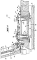
- the thermal cycler 18 has a hinged lid 28, the pro Recess 27 of the thermoblock 33 has an opening 29 that a Piercing the closure 87 of the inserted in the recess Test tube 21 allows with a pipetting needle. As from Fig. 2 can be seen, each of the is aligned when the hinged cover 28 is in the closed position Openings 29 with the longitudinal axis 31 of the corresponding test tube 21.
- the openings 29 of the hinged cover 28 allow access to the Contents of each test tube with the hinged lid 28 closed the pipetting needle 32 of a (not shown in FIG. 3)
- the pipetting device is inserted through one of the openings 29, the cover 87 pierced the test tube 21 with the pipetting needle 32 and then a certain volume of the contained in the test tube Aspirated liquid.
- the recesses 27 in Thermoblock 33 adapted to the conical area of the sample tube 21 are so that the peripheral wall of the sample tube 21 reliably the inner wall of the recess 27 for the best Heat transfer to the system.
- the Thermoblock 33 held and insulated as possible in a housing 34 has little mass with good thermal conductivity.
- Lid 28 preferably contains a heating element, e.g. a electrical resistance heater 52, which is used to heat the closed, sample tube arranged in the thermoblock 33 is used.
- a heating element e.g. a electrical resistance heater 52, which is used to heat the closed, sample tube arranged in the thermoblock 33 is used.
- the electrical resistance heater 52 in combination with one below described Peltier element 36 used to a desired Temperature profile (temperature profile over a certain time interval) in To achieve thermoblock 33.
- the Peltier element depending on the temperature to be reached within one Temperature profile used as a cooling or heating element.
- the interaction of the electrical resistance heater 52 with the Peltier element 36 enables the required speed of Changes in temperature of the thermoblock 33 and the required Achieve precision and homogeneity of temperature distribution. By the effect of the resistance heater 52 also becomes a possible one Condensation in the lid area of the sample tube 21 avoided.
- the hinged lid 28 preferably includes a closing and Pressing device for holding the closed, in the thermoblock 33 arranged test tubes 21.
- the hinged lid 28 has a resiliently held pressure plate 46, which each sample tube 21 with a defined force in the recesses 27 of the thermoblock 33 pushes in.
- Recesses 47 for receiving the dome-shaped Cover 87 of the test tube 21 and piercing openings 48 for the Pipetting needles 32 are coaxial with the test tubes 21 in the pressure plate 46 provided.
- a corrugated washer 49 can be provided as the spring element.
- the above-mentioned resistance heater 52 is preferably in the resilient pressure plate 46 included.
- Peltier element as a cooling or heating element
- a thermal cycler 18 preferably contains at least one Peltier element 36 as part of the thermal cycler 18 provided means for cyclically changing the temperature of the Thermoblocks 33.
- the Peltier element 36 is with one Heat transfer surface 37 over a large area with the lower surface of the Thermoblocks 33 and with its other heat transfer surface 38 thermally in large area to a heat sink 39 for heat dissipation Brought in contact.
- the heat sink 39 is preferably made of aluminum or Copper.
- a switchable fan 45 is provided for heat dissipation.
- the Peltier element 36 shown schematically in FIG. 2 is preferably an arrangement of such elements.
- the Peltier element 36 is used as a cooling or heating element. This Operation of the Peltier element 36 and its interaction with the electrical resistance heater 52 enables the required Temperature of the thermoblock within a temperature profile to reach.
- the Peltier element 36 To extend the life of the Peltier element 36, this is before thermodynamically based mechanical stress peaks preferably protected in that the Peltier element 36 by a central, spring-loaded fastening pressed against the thermoblock 33 is held.
- the Peltier element is elastic between the Heat transfer surfaces of the thermal block 33 and the heat sink 39 clamped.
- the heat sink 39 is e.g. by means of a compression spring 41 pressed with its contact surface against the Peltier element 36.
- the Spring tension can be adjusted using an adjusting screw 42, spring washer 43 and Ball joint 44 can be set, which the degrees of freedom of Heatsink 39 increased even further.
- the Peltier element 36 exclusively as a cold-generating element, i.e. used only as a cooling element. This will extend the Life of the Peltier element reached.
- thermoblock Additional heating element around the thermoblock
- the thermal cycler contains preferably in addition an electrical resistance heater 35, which around the thermal block 33 and along the circumference of its cylindrical, outer wall is arranged.
- the Peltier element 36 only becomes Used cooling. This has the advantage of relieving the strain on the Peltier element of thermal mechanical stress and carries thereby the lifespan of the Peltier element in the thermal cycler to extend.
- the lifting device 53 contains one Rocker 55, which serves as an ejection lever.
- the rocker 55 is at one end with a hinge of the hinged lid 28 connected.
- the rocker 55 is on other end free.
- the lifting device 53 also contains one Ejection disc 58, the axis of rotation of the thermoblock 33 is concentric, on which the rocker 55 is arranged.
- the Ejection disc 58 has an arrangement of at the periphery Recesses 61, which are used to remove the sample tube ring 23 from the Recesses 27 of the thermoblock 33 serve.
- the rocker 55 is guided on the axis of rotation 54 of the hinged cover 28.
- the rocker 55 On the axis of rotation, the rocker 55 has two tabs 56 with recesses 57, in which the axis of rotation 54 engages.
- the ejection disc is screwed onto the rocker 55.
- the ejection disk 58 has semicircular recesses 61 on its peripheral edge 59, which are project-precisely aligned with the recesses 27 in the thermoblock 33 or the cylindrical regions of the test tubes 21 which are inserted into the recesses 27 (FIG. 5).
- the peripheral edge 59 of the ejection disc 58 thus engages under the inner flange-like area 62 of the sample tube ring 23 or the flanges of the sample tube 21.
- FIGS. 4 and 5 show control pin 63 attached to hinged cover 28 at a distance e , which also engages in recess 57.
- the lifting device 53 is still inoperative.
- the pin 63 comes into contact with a control surface 64 of the recess 57 from a certain opening angle and causes the rocker 55 to pivot about the point P, which results in the sample container 21 being lifted out.
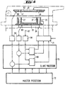
- a control and regulating device of the thermal cycler 18 via master-slave processors 72, 73 is shown schematically in FIG. 6.
- the temperature of the pressure plate 46 of the hinged lid 28, the Thermoblocks 33 and the environment is by means of temperature sensors 65, 66, 67 and the slave processor 73 via a temperature interface 68 fed.
- the master processor 72 interface to the user among other things the temperature setpoints, the time setpoints, the number of Temperature cycles and the speed of the heating and cooling processes entered.
- Predefined, stored temperature / time profiles can be created be selected and run. The entry is made via the keyboard 16 or another interface. This data is sent to the slave processor 73 supplied, which controls a power controller 71 via controller 69, which in turn supplies energy to the heating elements 35, 52 and Peltier element 36 regulates.
- the feedback (actual values) are via the Slave processor 73 fed to master processor 72 and processed there or displayed to the user. In this way, the user is informed about the current sample temperature, the temperatures already reached with Time and the temperatures to be reached with time informed.
- the operating status of the system is constantly monitored and logged. Errors that cannot be corrected by the system itself cause an automatic shutdown or error message.
- the temperature of the sample is the temperature of the thermoblock 33 calculated.
- the transfer function from Sample space for sample in the sample tube 21 determined. This function is essentially a low pass with dead time.
- the Power controller 71 is e.g. a performance FET with a matching one Protection and suppression circuit.
- the control and regulation described above enables use of the thermal cycler for samples in one used in the thermal cycler Heating the sample tube ring according to certain temperature profiles and to cool.
- the temperature profiles are defined by plateau temperatures defined duration, and the gradient that defines the time at which a plateau temperature must be reached.
- the condition is that all samples in the thermal cycler at the same time at the same temperatures to have.
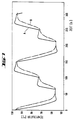
- Curve A shows the temperature curve on Thermoblock 33
- curve B shows the temperature profile of the liquid in the reaction container 21.
- the thermal cycler temperatures can be set between 40 and 98 degrees Celsius. Typically lie the lower temperatures between 50 and 60 degrees Celsius and the upper ones Temperatures between 90 and 96 degrees Celsius. If the middle Temperature is used, it is around 72 degrees Celsius. The one with the Thermalcycler achieved heating / cooling speed is 1 degree Celsius per second. A typical cycle lasts 120 seconds. If the corresponding temperatures are held for longer than 10 seconds the cycle time is extended accordingly.
Landscapes
- Health & Medical Sciences (AREA)
- Chemical & Material Sciences (AREA)
- Clinical Laboratory Science (AREA)
- Chemical Kinetics & Catalysis (AREA)
- Life Sciences & Earth Sciences (AREA)
- Biochemistry (AREA)
- General Health & Medical Sciences (AREA)
- Molecular Biology (AREA)
- Apparatus Associated With Microorganisms And Enzymes (AREA)
- Automatic Analysis And Handling Materials Therefor (AREA)
- Measuring Or Testing Involving Enzymes Or Micro-Organisms (AREA)
- Enzymes And Modification Thereof (AREA)
- General Induction Heating (AREA)
- Control Of Temperature (AREA)
- Control Of Combustion (AREA)
- Sampling And Sample Adjustment (AREA)
- Testing Resistance To Weather, Investigating Materials By Mechanical Methods (AREA)
- Investigating Or Analyzing Materials Using Thermal Means (AREA)
- Physical Or Chemical Processes And Apparatus (AREA)
- Organic Low-Molecular-Weight Compounds And Preparation Thereof (AREA)
Abstract
Description
Die Erfindung betrifft eine Vorrichtung zur automatischen
Durchführung von Polymerase-Kettenreaktionen in einer Vielzahl von
Reaktionsbehältern, wobei jedes Reaktionsbehälter mit einem Deckel
verschlossen ist und ein vorbestimmtes Volumen eines flüssigen
Reaktionsgemisches enthält, welche Vorrichtung folgende Komponenten
enthält:
Die Erfindung betrifft insbesondere eine Vorrichtung dieser Art, die vorzugsweise als integrierter Bestandteil eines automatischen Analysengerätes zur Durchführung der Polymerase-Kettenreaction ("Polymerase-Chain-Reaction") geeignet ist.The invention particularly relates to a device of this type which preferably as an integral part of an automatic Analyzer for carrying out the polymerase chain reaction ("Polymerase Chain Reaction") is suitable.
Eine Vorrichtung der oben erwähnten Art ist in der EP-A- 0 488 769 A2 beschrieben. A device of the type mentioned above is in EP-A-0 488 769 A2 described.
Eine Vorrichtung der oben erwähnten Art ist auch in der EP-A- 0 236 069 A2 beschrieben, in der ausserdem darauf hingewiesen wird, dass Mittel zur zyklischen Aenderung der Temperatur eines Trägers der oben erwähnten Art ein Peltier-Element enthalten können.A device of the type mentioned above is also in US Pat EP-A-0 236 069 A2, in which it is also pointed out that means for cyclically changing the temperature of a carrier of the type mentioned above may contain a Peltier element.
Vorrichtungen der eingangs genannten Art werden "Thermal cycler" genannt. Diese Bezeichnung wird in der nachstehenden Beschreibung verwendet.Devices of the type mentioned in the introduction become "thermal cyclers" called. This designation is used in the description below used.
Die in der EP-A- 0 488 769 A2 und in der EP-A- 0 236 069 A2 beschriebenen Vorrichtungen haben den Nachteil, dass durch die Temperatur-Aenderungen und die auf die Reaktionsbehälter wirkenden Druck die Aussenwände der Reaktionsbehälter an den Wänden der Kammer des Trägers haften. Die dadurch erwirkte kraftschlüssige Verbindung erschwert das Entfernen der Reaktionsbehälter aus dem Trägers.The in EP-A-0 488 769 A2 and in EP-A-0 236 069 A2 Devices described have the disadvantage that Temperature changes and those acting on the reaction vessels Press the outer walls of the reaction vessels against the walls of the chamber of the wearer. The resulting positive connection makes it difficult to remove the reaction containers from the carrier.
Es ist zwar aus der DE-A-3024210 A1 ein Metallblockthermostat bekannt, bei dem Reaktionsgefässe mittels einer Trägerplatte gleichzeitig in Bohrungen ein- bzw. ausführbar sind. Nachteilig dabei ist, dass dafür zusätzliche Hubtriebe zum Transport der Trägerplatte erforderlich sind, was die Herstellungskosten erheblich erhöht.Although it is a metal block thermostat from DE-A-3024210 A1 is known, in which the reaction vessels simultaneously in a support plate Bores can be inserted or executed. The disadvantage is that for that additional lifting drives for transporting the carrier plate are required, which the manufacturing costs increased significantly.
Der Erfindung liegt daher die Aufgabe zugrunde eine Vorrichtung der eingangs erwähnten Art zur Verfügung zu stellen, mit welcher die oben erwähnten Nachteile behoben werden können.The invention is therefore based on the object of a device to provide the kind mentioned above, with which the above mentioned disadvantages can be remedied.
Diese Aufgabe wird erfindungsgemäss mit einer Vorrichtung gemäss
Patentanspruch 1 gelöst.This object is achieved according to the invention with a
Die erfindungsgemässe Vorrichtung erleichtert die Entfernung der Reaktionsbehälter aus den Kammern des Trägers nach Durchführung der Polymerase-Kettenreaktionen.The inventive device facilitates the removal of the Reaction container from the chambers of the carrier after performing the Polymerase chain reactions.
Ein weiterer Vorteil der erfindungsgemässen Vorrichtung ist, dass sie den oben erwähnten Nachteil der bekannten Vorrichtungen dieser Art auf möglichst einfache Weise und mit geringem Aufwand behebt.Another advantage of the device according to the invention is that it the above-mentioned disadvantage of the known devices of this type fixes as simple as possible and with little effort.
Ein Ausführungsbeispiel der Erfindung wird im folgenden anhand der beiliegenden Zeichnungen beschrieben. Es zeigen:
- Fig. 1
- einen aus einem Analysengerät herausgenommenen
Thermalcycler-
Teil 2, der Thermalcycler 18 und 19 enthält, wobei der Thermalcycler 18 geöffnet und einen darausentnommenen Proberöhrchenring 23 gezeigt wird, - Fig.2
- einen Schnitt durch die Linie II-II in Fig. 1, wobei der Thermalcycler 18 geschlossen ist,
- Fig. 3
- eine perspektivische Ansicht des Thermalcyclers 18 gemäss
Fig. 1, welcher durch eine
Aushebevorrichtung 53 ergänzt ist, - Fig. 4
- einen gegenüber Fig. 2 vergrösserten Schnitt durch den Thermalcycler im geschlossenen Zustand,
- Fig. 5
- einen Thermalcycler gemäss Fig. 4 im geöffneten Zustand,
- Fig. 6
- eine schematische Darstellung einer "Master-Slave"-Steuerung zur Regelung und Ueberwachung der Betriebsparameter eines Thermalcyclers,
- Fig. 7
- ein Temperatur-Zeit-Diagramm eines im Master-Prozessor gespeicherten Temperaturverlaufes bzw. die daraus resultierenden Temperaturen des Thermoblocks und der Probe.
- Fig. 1
- a
thermal cycler part 2 removed from an analysis device, which containsthermal cyclers thermal cycler 18 being opened and asample tube ring 23 removed therefrom being shown, - Fig. 2
- 2 shows a section through the line II-II in FIG. 1, the
thermal cycler 18 being closed, - Fig. 3
- 2 shows a perspective view of the
thermal cycler 18 according to FIG. 1, which is supplemented by alifting device 53, - Fig. 4
- 2 enlarged section through the thermal cycler in the closed state,
- Fig. 5
- 4 in the open state,
- Fig. 6
- 1 shows a schematic representation of a "master-slave" control for regulating and monitoring the operating parameters of a thermal cycler,
- Fig. 7
- a temperature-time diagram of a temperature curve stored in the master processor or the resulting temperatures of the thermoblock and the sample.
Der in den Figuren 1 und 2 dargestellte Thermalcycler-Teil 2 als solche
fällt nicht unter den Patentanspruch 1.The
In der nachstehenden Beschreibung wird mit Thermalcycler eine
Vorrichtung bezeichnet, die zur automatischen Durchführung von
Temperaturzyklen in wenigstens einem mit einem Deckel geschlossenen
Proberöhrchen 21 dient, das ein vorbestimmtes Volumens eines flüssigen
Reaktionsgemisches enthält. In the description below, thermal cycler is used
Designated device for the automatic implementation of
Temperature cycles in at least one closed with a
Nachstehend wird ein Thermalcycler beschrieben, der vorzugsweise als Bestandteil eines automatischen Analysengerätes zur Durchführung der Polymerase-Kettenreaction geeignet ist. Das Analysengerät ist beispielsweise zur Durchführung von Immunoassays ausgelegt.A thermal cycler that is preferred is described below as part of an automatic analyzer for implementation the polymerase chain reaction is suitable. The analyzer is designed for example for performing immunoassays.
In Fig. 1 ist ein Thermalcycler-Teil 2 aus einem Analysengerät 1
ausgebaut dargestellt. Dieser Thermalcycler-Teil 2 enthält z.B. zwei
identische Thermalcycler 18, 19 und eine Stand-by Position 22. Die
nachstehende Beschreibung des Thermalcycler 18 gilt auch für den
Thermalcycler 19.1 shows a
Der Thermalcycler 18 enthält folgende Komponenten :
Der Thermoblock 33 besteht aus einem Material, das eine hohe
thermische Leitfähigkeit hat. Der Thermoblock 33 ist vorzugsweise ein
Körper aus Aluminium oder Silber. Der Thermoblock 33 hat eine obere
Fläche, eine untere Fläche und eine zylindrische Aussenwand, wobei jede
der Ausnehmungen 27 des Thermoblocks 33 eine Oeffnung hat, die in der
oberen Fläche des Trägers liegt.The
Wie in Figuren 1 und 3 dargestellt, sind z.B. zwölf Proberöhrchen 21 zu
einem Proberöhrchenring 23 zusammengefasst. Die Proberöhrchen 21 sind
im unteren Bereich konisch, im oberen Bereich zylindrisch geformt und
durch einen Deckel 87 dicht verschlossen. Wie in Fig. 1 und 3 gut zu
erkennen ist, kann eine derartige Proberöhrchenanordnung 23 in
entsprechende Ausnehmungen 27 des Thermoblocks 33 des Thermalcyclers
18 eingesetzt werden.As shown in Figures 1 and 3, e.g. twelve
Der Thermalcyclers 18 hat einen klappbaren Deckel 28, der pro
Ausnehmung 27 des Thermoblocks 33 eine Oeffnung 29 aufweist, die ein
Durchstechen des Verschlusses 87 des in der Ausnehmung eingesetzten
Proberöhrchens 21 mit einer Pipettiernadel ermöglicht. Wie aus Fig. 2
ersichtlich, fluchtet bei geschlossener Stellung des Klappdeckels 28 jede der
Oeffnungen 29 mit der Längsachse 31 des entsprechenden Proberöhrchens
21.The
Die Oeffnungen 29 des Klappdeckels 28 ermöglichen den Zugriff zum
Inhalt jedes Proberöhrchens bei geschlossenem Klappdeckel 28. Dafür wird
die Pipettiernadel 32 einer (in Figur 3 nicht dargestellten)
Pipettiereinrichtung durch eine der Oeffnungen 29 eingeführt, der Deckel 87
des Proberöhrchens 21 mit der Pipettiernadel 32 durchgestochen und
anschliessend ein bestimmtes Volumen der im Proberöhrchen enthaltenen
Flüssigkeit abgesaugt.The
Es ist aus Fig. 2 ersichtlich, dass die Ausnehmungen 27 im
Thermoblock 33 an den konischen Bereich der Proberöhrchen 21 angepasst
sind, sodass die Umfangswandung des Proberöhrchens 21 zuverlässig an
die Innenwandung der Ausnehmung 27, zwecks bester
Wärmeübertragung, zur Anlage kommen kann. Um die thermische
Reaktionsgeschwindigkeit, Präzision und Homogenität zu erhöhen, ist der
Thermoblock 33 möglichst wärmeisoliert in einem Gehäuse 34 gehaltert und
weist wenig Masse bei guter thermischer Leitfähigkeit auf.It can be seen from Fig. 2 that the
Der Deckel 28 enthält vorzugsweise ein Heizelement , z.B. eine
elektrische Widerstandsheizung 52, die zum Beheizen der verschlossenen,
im Thermoblock 33 angeordneten Proberöhrchen dient.
In einer ersten Ausführungsform des Thermalcyclers wird die
elektrische Widerstandsheizung 52 in Kombination mit einem nachstehend
beschriebenen Peltier-Element 36 verwendet, um ein gewünschtes
Temperaturprofil (Temperaturverlauf über ein bestimmtes Zeitintervall) im
Thermoblock 33 zu erzielen. In dieser Ausführungsform wird das Peltier-Element
je nach der zu erreichenden Temperatur innerhalb eines
Temperaturprofils als Kühl- oder als Heizelement verwendet. In a first embodiment of the thermal cycler, the
Die Zusammenwirkung der elektrischen Widerstandsheizung 52 mit
dem Peltier-Element 36 ermöglicht, die erforderliche Schnelligkeit der
Temperaturänderungen des Thermoblocks 33 sowie die erforderliche
Präzision und Homogenität der Temperaturverteilung zu erreichen. Durch
die Wirkung der Widerstandsheizung 52 wird ausserdem eine etwaige
Kondensatbildung im Deckelbereich des Proberöhrchens 21 vermieden.The interaction of the
Der Klappdeckel 28 enthält vorzugsweise eine Verschliess- und
Anpresseinrichtung zum Festhalten der verschlossenen, im Thermoblock
33 angeordneten Proberöhrchen 21. Hierfür weist der Klappdeckel 28 eine
federnd gehaltene Andruckplatte 46 auf, welche jedes Proberöhrchen 21 mit
einer definierten Kraft in die Ausnehmungen 27 des Thermoblocks 33
hineindrückt. Ausnehmungen 47 zur Aufnahme der kalottenförmigen
Deckel 87 der Proberöhrchen 21 sowie Durchstichöffnungen 48 für die
Pipettiernadel 32 sind koaxial zu den Proberöhrchen 21 in der Andruckplatte
46 vorgesehen. Als Federelement kann eine Wellscheibe 49 vorgesehen sein.
Durch einen Sicherungsring 51 ist die Andruckplatte 46 bei geöffnetem
Klappdeckel 28 gegen Herausfallen gesichert.The hinged
Die oben erwähnte Widerstandsheizung 52 ist vorzugsweise in der
federnden Andruckplatte 46 enthalten.The above-mentioned
Wie in Fig. 2 dargestellt, enthält ein Thermalcycler 18 vorzugsweise
wenigstens ein Peltier-Element 36 als Teil der im Thermalcycler 18
vorgesehenen Mittel zur zyklischen Aenderung der Temperatur des
Thermoblocks 33. Das Peltier-Element 36 ist mit seiner einen
Wärmeübergangsfläche 37 grossflächig mit der unteren Fläche des
Thermoblocks 33 und mit seiner anderen Wärmeübergangsfläche 38
grossflächig an einen Kühlkörper 39 zur Wärmeabfuhr thermisch in
Kontakt gebracht. Der Kühlkörper 39 ist vorzugsweise aus Aluminium oder
Kupfer. Zur Wärmeabfuhr ist ein schaltbarer Ventilator 45 vorgesehen.As shown in Figure 2, a
Das in Fig. 2 schematisch dargestellte Peltier-Element 36 ist
vorzugsweise eine Anordnung solcher Elemente. The
In der oben erwähnten ersten Ausführungsform des Thermalcyclers
wird das Peltier-Element 36 als Kühl- oder als Heizelement verwendet. Diese
Betriebsweise des Peltier-Elementes 36 und seine Zusammenwirkung mit
der elektrischen Widerstandsheizung 52 ermöglicht, die erforderliche
Temperatur des Thermoblocks innerhalb eines Temperaturprofils zu
erreichen.In the above-mentioned first embodiment of the thermal cycler
the
Zur Verlängerung der Lebensdauer des Peltier-Elementes 36 ist dieser
vor thermodynamisch begründeten mechanischen Spannungsspitzen
vorzugsweise dadurch geschützt, dass das Peltier-Element 36 durch eine
zentrale, federvorgespannte Befestigung gegen den Thermoblock 33 gepresst
gehalten wird. Hierfür wird das Peltier-Element elastisch zwischen den
Wärmeübertragungsflächen des Thermoblocks 33 und des Kühlkörpers 39
eingespannt. Dafür wird der Kühlkörper 39 z.B. mittels einer Druckfeder 41
mit seiner Kontaktfläche gegen das Peltier-Element 36 gedrückt. Die
Federspannung kann über eine Einstellschraube 42, Federteller 43 und ein
Kugelgelenk 44 eingestellt werden, welches die Freiheitsgrade des
Kühlkörpers 39 noch weiter erhöht.To extend the life of the
In einer Variante des hier beschriebenen Ausführungsbeispiels wird
das Peltier-Elementes 36 ausschliesslich als kälteerzeugendes Element, d.h.
nur als Kühlelement verwendet. Dadurch wird eine Verlängerung der
Lebensdauer des Peltier-Elementes erreicht.In a variant of the embodiment described here
the
In einer zweiten Ausführungsform des Thermalcyclers enthält dieser
vorzugsweise zusätzlich eine elektrische Widerstandsheizung 35, die um
den Thermoblock 33 und entlang des Umfangs seiner zylindrischen,
äusseren Wand angeordnet ist. Bei Verwendung dieses zusätzliches
Heizelementes im Thermalcycler wird das Peltier-Element 36 nur zum
Kühlen verwendet. Dies bringt den Vorteil einer Entlastung des Peltier-Elements
von thermisch bedingtem mechanischem Stress und trägt
dadurch dazu bei die Lebensdauer des Peltier-Elements im Thermalcycler
zu verlängern.In a second embodiment of the thermal cycler, it contains
preferably in addition an
Durch die Temperatur-Aenderungen und der Wirkung der Feder 49
haften die konischen Bereiche der Proberöhrchen 21 an den Wänden der
Ausnehmungen 27 des Thermoblocks 33. Die dadurch erwirkte
kraftschlüssige Verbindung erschwert das Entfernen der Proberöhrchen 21
aus dem Thermalcycler 2. Aus diesem Grunde wurde in der
Ausführungsform gemäss Fig. 3 bis 5 eine Aushebevorrichtung 53
vorgeschlagen, welche die Entnahme des Proberöhrchenringes 23 aus dem
Thermoblock 33 erheblich erleichtert.Due to the temperature changes and the action of
Wie aus Figuren 3-5 ersichtlich, enthält die Aushebevorrichtung 53 eine
Wippe 55, die als Auswurfhebel dient. Die Wippe 55 ist an einem Ende mit
einem Scharnier des klappbaren Deckels 28 verbunden. Die Wippe 55 ist am
anderen Ende frei. Die Aushebevorrichtung 53 enthält ferner eine
Auswurfscheibe 58, die mit der Rotationssymmetrieachse des Thermoblocks
33 konzentrisch ist, auf dem die Wippe 55 angeordnet ist. Die
Auswurfscheibe 58 hat an der Peripherie eine Anordnung von
Ausnehmungen 61, die zur Entnahme des Proberöhrchenringes 23 aus den
Ausnehmungen 27 des Thermoblocks 33 dienen.As can be seen from FIGS. 3-5, the lifting
Wie aus Fig. 3 ersichtlich, wird die Wippe 55 auf der Drehachse 54 des
Klappdeckels 28 geführt. Drehachsenseitig weist die Wippe 55 zwei Laschen
56 mit Ausnehmungen 57 auf, in welche die Drehachse 54 eingreift. Die
Auswurfscheibe ist auf die Wippe 55 aufgeschraubt. Die Auswurfscheibe 58
weist an seinem peripheren Rand 59 halbkreisförmige Ausnehmungen 61
auf, welche projektionsgenau mit den Ausnehmungen 27 im Thermoblock
33, bzw. den zylindrischen Bereichen der Proberöhrchen 21 fluchten, welche
in die Ausnehmungen 27 eingesetzt sind (Fig. 5). Der periphere Rand 59 der
Auswurfscheibe 58 untergreift somit den inneren flanschartigen Bereich 62
des Proberöhrchenringes 23 bzw. die Flansche der Proberöhrchen 21. Die
Gestalt und Funktion der Ausnehmung 57 in den Laschen 56 der Wippe 55
im Zusammenhang mit der Drehachse 54 des Klappdeckels 28 sowie eines
am Klappdeckel 28 in einem Abstand e angebrachten Steuerstiftes 63,
welcher ebenso in die Ausnehmung 57 eingreift, ist aus Figuren 4 und 5
ersichtlich. Bei geschlossenem Klappdeckel 28 ist die Aushebevorrichtung
53 noch funktionslos. Beim Öffnen des Klappdeckels 28 gerät der Stift 63 ab
einem gewissen Oeffnungswinkel in Kontakt mit einer Steuerfläche 64 der
Ausnehmung 57 und bewirkt ein Verschwenken der Wippe 55 um den
Punkt P, was ein Ausheben der Probenbehälter 21 zur Folge hat. Durch die
Kippbewegung der Wippe 55 um den Punkt P bzw. durch die zunehmende
Schrägstellung der Auswurfscheibe 58 wird bewirkt, dass sich die den
einzelnen Proberöhrchen 21 zugeordneten Losbrechkräfte zeitlich versetzt
manifestieren, so dass die Proberöhrchen 21 nach und nach aus ihren
Ausnehmungen 27 gelöst werden. Der Kraftaufwand und die
Materialbeanspruchung wird dadurch auf niedrigem Niveau gehalten und
der Bedienungskomfort erhöht.3, the
Eine Steuer- und Regeleinrichtung des Thermalcyclers 18 über Master-Slave-Prozessoren
72, 73 ist in Fig. 6 schematisch dargestellt.A control and regulating device of the
Die Temperatur der Andruckplatte 46 des Klappdeckels 28, des
Thermoblocks 33 und der Umgebung wird mittels Temperaturfühler 65, 66,
67 erfasst und über ein Temperatur-Interface 68 dem Slave-Prozessor 73
zugeführt. Im Master-Prozessor 72 (Schnittstelle zum Benutzer) werden
unter anderem die Temperatursollwerte, die Zeitsollwerte, die Anzahl der
Temperaturzyklen und die Geschwindigkeit der Heiz- und Kühlvorgänge
eingegeben.The temperature of the
Es können bereits vorbestimmte, gespeicherte Temperatur/Zeitprofile
gewählt und abgefahren werden. Die Eingabe erfolgt über die Tastatur 16
oder eine andere Schnittstelle. Diese Daten werden dem Slave-Prozessor 73
zugeführt, welcher über Regler 69 einen Leistungssteller 71 ansteuert,
welcher wiederum die Energieversorgung der Heizelemente 35, 52 und des
Peltier-Elements 36 regelt. Die Rückmeldungen (Ist-Werte) werden über den
Slave-Prozessor 73 dem Master-Prozessor 72 zugeführt und dort verarbeitet
bzw. dem Benutzer angezeigt. Auf diese Weise wird der Benutzer über die
momentane Probentemperatur, die bereits erreichten Temperaturen mit
Zeitangabe und die noch zu erreichenden Temperaturen mit Zeitangabe
informiert.Predefined, stored temperature / time profiles can be created
be selected and run. The entry is made via the keyboard 16
or another interface. This data is sent to the
Der Betriebszustand des Systems wird ständig überwacht und protokolliert. Fehler, die nicht vom System selbst behoben werden können, bewirken eine automatische Abschaltung oder Fehlermeldung.The operating status of the system is constantly monitored and logged. Errors that cannot be corrected by the system itself cause an automatic shutdown or error message.
Die Temperatur der Probe wird aus der Temperatur des Thermoblocks
33 rechnerisch ermittelt. Dazu wird die Uebertragungsfunktion vom
Probenraum zur Probe im Proberöhrchen 21 bestimmt. Diese Funktion ist
im wesentlichen ein Tiefpass mit Totzeit.The temperature of the sample is the temperature of the
Anhand geeigneter Regelalgorythmen (abgetastete Systeme) wird
jeweils die Stellgrösse berechnet, die nötig ist, um die Temperatur der Probe
der vorgegebenen Sollwerttemperatur nachzuführen. Diese Berechnungen
werden mit einem Signalprozessor durchgeführt. Die berechnete Stellgrösse
wird in Form einer Pulsweite dem Leistungssteller 71 zugeführt. Der
Leistungssteller 71 ist z.B. ein Leistungs-FET mit einer dazu passenden
Schutz- und Entstörschaltung.Using suitable control algorithms (scanned systems)
each calculates the manipulated variable that is necessary to measure the temperature of the sample
track the specified setpoint temperature. These calculations
are carried out with a signal processor. The calculated manipulated variable
is supplied to the
Die oben beschriebene Steuerung und Regelung ermöglicht den Einsatz des Thermalcyclers um Proben in einem im Thermalcyclers eingesetzten Probenröhrchenring nach bestimmten Temperaturprofilen zu heizen und zu kühlen. Die Temperaturprofile sind definiert durch Plateau-Temperaturen definierter Dauer, und der Gradient, der die Zeit definiert, bei der eine Plateau-Temperatur erreicht sein muss. Bedingung ist, dass alle Proben im Thermalcycler zur gleichen Zeit die gleichen Temperaturen haben.The control and regulation described above enables use of the thermal cycler for samples in one used in the thermal cycler Heating the sample tube ring according to certain temperature profiles and to cool. The temperature profiles are defined by plateau temperatures defined duration, and the gradient that defines the time at which a plateau temperature must be reached. The condition is that all samples in the thermal cycler at the same time at the same temperatures to have.
In Fig. 7 sind beispielsweise Temperaturverläufe aus einem
Zyklusprozess aufgezeigt. Kurve A zeigt den Temperaturverlauf am
Thermoblock 33, die Kurve B zeigt den Temperaturverlauf der Flüssigkeit
im Reaktionsbehälter 21. Mit dem Thermalcycler können Temperaturen
zwischen 40 und 98 Grad Celsius eingestellt werden. Typischerweise liegen
die untere Temperaturen zwischen 50 und 60 Grad Celsius und die oberen
Temperaturen zwischen 90 und 96 Grad Celsius. Wenn die mittlere
Temperatur benutzt wird, liegt sie um 72 Grad Celsius. Die mit dem
Thermalcycler erzielte Heiz-/Kühl-Geschwindigkeit beträgt 1 Grad Celsius
pro Sekunde. Ein typisches Zyklus hat eine Dauer von 120 Sekunden. Wenn
die entsprechende Temperaturen länger als 10 Sekunden gehalten werden
müssen, verlängert sich die Zyklusdauer entsprechend.7 shows, for example, temperature profiles from one
Cycle process shown. Curve A shows the temperature curve on
Claims (1)
- A device for automatic performance of polymerase chain reactions in a number of test tubes, each test tube being closed by a lid and containing a predetermined volume of a liquid reaction mixture, the device containing the following components:which device is characterised in that(a) a holder (33) having an arrangement of chambers (27) for holding the test tubes (21), each chamber being adapted to receive the lower part of a test tube, said holder (33) consisting of a material which has a high thermal conductivity and having an upper surface, a bottom surface, and a cylindrical outer wall, each of the chambers (27) of the holder (33) having an opening located in the upper surface of the holder,(b) test tubes (21) disposed in the chambers (27) of the holder (33) and each closed by a lid (87),(c) a computer-controlled automatic control system, and(d) means controlled by the automatic control system for cyclic alteration of the temperature of the holder,(i) the arrangement of the chambers (27) in the holder (33) is annular,(ii) it comprises a hinged lid (28) for securing the closed test tubes (21) disposed in the holder, said lid having a pivot (54) and a control pin (63) disposed at a distance from the longitudinal axis of the pivot (54), and(iii) it contains a lifting-out device for facilitating removal of the test tubes (21) from the chambers (27) in the holder (33), said lifting-out device comprising an ejection lever (55) having the recesses (57) at one end above lugs (56), is connected to a hinge of the hinged lid (28) and at the other end is free, and an ejection disc (58) which is concentric with the rotational axis of symmetry of the holder (33), is fixed on an ejection lever (55) and has at the periphery an arrangement of recesses (61) serving for removal of the test tubes (21) from the chambers (27), the pivot (54) and the control pin (63) so engaging in one of the recesses (57) of the lugs (56) that at a specific opening angle of the hinged lid (28) the control pin (63) comes into contact with a control surface of the recess (57) and causes pivoting of the ejection lever (55).
Applications Claiming Priority (4)
| Application Number | Priority Date | Filing Date | Title |
|---|---|---|---|
| CH271793 | 1993-09-10 | ||
| CH2717/93 | 1993-09-10 | ||
| CH271793 | 1993-09-10 | ||
| EP94113574A EP0642831B1 (en) | 1993-09-10 | 1994-08-31 | Device and process for automatically carrying out temperature cycling |
Related Parent Applications (2)
| Application Number | Title | Priority Date | Filing Date |
|---|---|---|---|
| EP94113574A Division EP0642831B1 (en) | 1993-09-10 | 1994-08-31 | Device and process for automatically carrying out temperature cycling |
| EP94113574.1 Division | 1994-08-31 |
Publications (3)
| Publication Number | Publication Date |
|---|---|
| EP0807467A2 EP0807467A2 (en) | 1997-11-19 |
| EP0807467A3 EP0807467A3 (en) | 1998-06-03 |
| EP0807467B1 true EP0807467B1 (en) | 2001-12-19 |
Family
ID=4240017
Family Applications (3)
| Application Number | Title | Priority Date | Filing Date |
|---|---|---|---|
| EP97112702A Expired - Lifetime EP0807467B1 (en) | 1993-09-10 | 1994-08-31 | Device for automatically carrying out polymerase chain reactions |
| EP97112710A Expired - Lifetime EP0807468B1 (en) | 1993-09-10 | 1994-08-31 | Device for automatically carrying out polymerase chain reactions |
| EP94113574A Expired - Lifetime EP0642831B1 (en) | 1993-09-10 | 1994-08-31 | Device and process for automatically carrying out temperature cycling |
Family Applications After (2)
| Application Number | Title | Priority Date | Filing Date |
|---|---|---|---|
| EP97112710A Expired - Lifetime EP0807468B1 (en) | 1993-09-10 | 1994-08-31 | Device for automatically carrying out polymerase chain reactions |
| EP94113574A Expired - Lifetime EP0642831B1 (en) | 1993-09-10 | 1994-08-31 | Device and process for automatically carrying out temperature cycling |
Country Status (10)
| Country | Link |
|---|---|
| US (2) | US5616301A (en) |
| EP (3) | EP0807467B1 (en) |
| JP (1) | JPH07151764A (en) |
| AT (3) | ATE199222T1 (en) |
| CA (1) | CA2130013C (en) |
| DE (3) | DE59410020D1 (en) |
| DK (1) | DK0642831T3 (en) |
| ES (3) | ES2155456T3 (en) |
| GR (1) | GR3035810T3 (en) |
| PT (1) | PT642831E (en) |
Families Citing this family (182)
| Publication number | Priority date | Publication date | Assignee | Title |
|---|---|---|---|---|
| US6277570B1 (en) | 1993-04-13 | 2001-08-21 | Naxcor | Nucleic acid sequence detection employing probes comprising non-nucleosidic coumarin derivatives as polynucleotide-crosslinking agents |
| US5767259A (en) | 1994-12-27 | 1998-06-16 | Naxcor | Oligonucleotides containing base-free linking groups with photoactivatable side chains |
| US6495676B1 (en) | 1993-04-13 | 2002-12-17 | Naxcor | Nucleic acid sequence detection employing probes comprising non-nucleosidic coumarin derivatives as polynucleotide-crosslinking agents |
| CA2130517C (en) * | 1993-09-10 | 1999-10-05 | Walter Fassbind | Array of reaction containers for an apparatus for automatic performance of temperature cycles |
| CA2130013C (en) * | 1993-09-10 | 1999-03-30 | Rolf Moser | Apparatus for automatic performance of temperature cycles |
| DE19512835C2 (en) * | 1995-01-12 | 1999-06-24 | Joachim Dipl Ing Schulz | Thermal shaker |
| DE19519015C1 (en) * | 1995-05-24 | 1996-09-05 | Inst Physikalische Hochtech Ev | Miniaturised multi-chamber thermo-cycler for polymerase chain reaction |
| DE19521947C1 (en) * | 1995-06-16 | 1996-08-22 | Medipro Medizinische Diagnosti | Vibrating water bath assembly with at least two individually temp.-controlled positions |
| DE19534632A1 (en) * | 1995-09-19 | 1997-03-20 | Boehringer Mannheim Gmbh | System for temperature change treatment of sample liquids |
| DE19540877C2 (en) * | 1995-11-02 | 1998-02-26 | Byk Sangtec Diagnostica | Modular reagent cartridge |
| DE29519602U1 (en) * | 1995-12-11 | 1996-04-18 | Reimann, Hans-Jürgen, Prof. Dr. Dr., 82067 Ebenhausen | Mobile incubation device |
| US5830657A (en) * | 1996-05-01 | 1998-11-03 | Visible Genetics Inc. | Method for single-tube sequencing of nucleic acid polymers |
| US6635492B2 (en) | 1996-01-25 | 2003-10-21 | Bjs Company Ltd. | Heating specimen carriers |
| US5882903A (en) * | 1996-11-01 | 1999-03-16 | Sarnoff Corporation | Assay system and method for conducting assays |
| DE29706031U1 (en) * | 1996-11-22 | 1997-08-21 | Schulz, Joachim, Dipl.-Ing., 06502 Thale | Device for tempering and shaking samples in sample vessels |
| US6045755A (en) * | 1997-03-10 | 2000-04-04 | Trega Biosciences,, Inc. | Apparatus and method for combinatorial chemistry synthesis |
| EP1127619B1 (en) * | 1997-03-28 | 2003-10-08 | PE Corporation (NY) | Assembly for thermal cycler for PCR |
| EP2090366B1 (en) * | 1997-03-28 | 2012-12-19 | Life Technologies Corporation | Improvements in thermal cycler for PCR |
| US7133726B1 (en) | 1997-03-28 | 2006-11-07 | Applera Corporation | Thermal cycler for PCR |
| WO1999009137A1 (en) * | 1997-08-20 | 1999-02-25 | Biopore, Inc. | Cassette device and system to facilitate cryopreservation |
| US5942432A (en) * | 1997-10-07 | 1999-08-24 | The Perkin-Elmer Corporation | Apparatus for a fluid impingement thermal cycler |
| DE29720432U1 (en) | 1997-11-19 | 1999-03-25 | Heimberg, Wolfgang, Dr., 85560 Ebersberg | robot |
| US6251686B1 (en) * | 1998-02-26 | 2001-06-26 | Edward J. Studer | Liquid transfer apparatus |
| JP4511034B2 (en) | 1998-05-01 | 2010-07-28 | ジェン−プロウブ インコーポレイテッド | Automated diagnostic analyzer and method |
| EP0953379B1 (en) * | 1998-05-01 | 2004-07-21 | F. Hoffmann-La Roche Ag | Apparatus for simultaneously monitoring reactions taking place in a plurality of reaction vessels |
| US8337753B2 (en) | 1998-05-01 | 2012-12-25 | Gen-Probe Incorporated | Temperature-controlled incubator having a receptacle mixing mechanism |
| DE69826834T2 (en) * | 1998-05-04 | 2005-12-08 | F. Hoffmann-La Roche Ag | Thermocycling apparatus with an automatically positionable lid |
| US6780617B2 (en) * | 2000-12-29 | 2004-08-24 | Chen & Chen, Llc | Sample processing device and method |
| US6318191B1 (en) * | 1998-06-24 | 2001-11-20 | Chen & Chen, Llc | Fluid sample testing system |
| US7799521B2 (en) * | 1998-06-24 | 2010-09-21 | Chen & Chen, Llc | Thermal cycling |
| US6413780B1 (en) * | 1998-10-14 | 2002-07-02 | Abbott Laboratories | Structure and method for performing a determination of an item of interest in a sample |
| DE19859586C1 (en) * | 1998-12-22 | 2000-07-13 | Mwg Biotech Ag | Thermal cycler device |
| EP1045038A1 (en) * | 1999-04-08 | 2000-10-18 | Hans-Knöll-Institut Für Naturstoff-Forschung E.V. | Rapid heat block thermocycler |
| DE19926937A1 (en) * | 1999-06-14 | 2001-01-04 | Biopsytec Gmbh | Holder for standard laboratory reaction tube with captive lid uses lid to assist fixing in holder |
| US6472186B1 (en) | 1999-06-24 | 2002-10-29 | Andre Quintanar | High speed process and apparatus for amplifying DNA |
| US6657169B2 (en) * | 1999-07-30 | 2003-12-02 | Stratagene | Apparatus for thermally cycling samples of biological material with substantial temperature uniformity |
| DE50001774D1 (en) | 1999-09-29 | 2003-05-22 | Tecan Trading Ag Maennedorf | Thermal cycler and lifting element for microtiter plate |
| EP1456642A1 (en) * | 1999-12-22 | 2004-09-15 | Applera Corporation | A lid mechanism |
| US7169355B1 (en) | 2000-02-02 | 2007-01-30 | Applera Corporation | Apparatus and method for ejecting sample well trays |
| US6599484B1 (en) * | 2000-05-12 | 2003-07-29 | Cti, Inc. | Apparatus for processing radionuclides |
| US6720187B2 (en) | 2000-06-28 | 2004-04-13 | 3M Innovative Properties Company | Multi-format sample processing devices |
| US6734401B2 (en) * | 2000-06-28 | 2004-05-11 | 3M Innovative Properties Company | Enhanced sample processing devices, systems and methods |
| JP4773035B2 (en) * | 2000-06-28 | 2011-09-14 | スリーエム イノベイティブ プロパティズ カンパニー | Enhanced sample processing apparatus, system and method |
| US6825041B2 (en) * | 2001-03-16 | 2004-11-30 | Beckman Coulter, Inc. | Method and system for automated immunochemistry analysis |
| DE10115848A1 (en) * | 2001-03-30 | 2002-10-10 | Biometra Biomedizinische Analy | Device for thermally influencing, preferably liquid, sample material contained in a container |
| US6698213B2 (en) * | 2001-05-22 | 2004-03-02 | Integrated Biosystems, Inc. | Systems and methods for freezing and storing biopharmaceutical material |
| GB0121827D0 (en) * | 2001-09-10 | 2001-10-31 | Bjs Company Ltd | Zone heating of specimen carriers |
| JP4513085B2 (en) | 2001-09-11 | 2010-07-28 | アイキューム インク | Sample container |
| US20030072685A1 (en) * | 2001-10-11 | 2003-04-17 | Goldman Jeffrey A. | Heat conducting sample block |
| EP1450957A1 (en) * | 2001-10-26 | 2004-09-01 | Sequenom, Inc. | Method and apparatus for high-throughput sample handling process line |
| DE20117661U1 (en) * | 2001-10-29 | 2003-03-13 | MWG-BIOTECH AG, 85560 Ebersberg | Apparatus for heating reaction vessel wells in micro-titration plate has base body to hold them, containing temperature control block which is moved up and down through movements of swing lid |
| JPWO2003055973A1 (en) * | 2001-12-26 | 2005-05-12 | オリンパス株式会社 | Reaction vessel and reaction vessel holding mechanism |
| US6889468B2 (en) | 2001-12-28 | 2005-05-10 | 3M Innovative Properties Company | Modular systems and methods for using sample processing devices |
| US6677151B2 (en) * | 2002-01-30 | 2004-01-13 | Applera Corporation | Device and method for thermal cycling |
| US20040241723A1 (en) * | 2002-03-18 | 2004-12-02 | Marquess Foley Leigh Shaw | Systems and methods for improving protein and milk production of dairy herds |
| DE10243209A1 (en) * | 2002-03-22 | 2003-10-02 | Endress & Hauser Wetzer Gmbh | Device for cooling sampling unit comprises container for receiving sample bottle and/or sample container arranged in sampling unit, cooling unit and vaporizer |
| KR100698039B1 (en) * | 2002-06-14 | 2007-03-23 | 엘지.필립스 엘시디 주식회사 | Cleaning jig |
| US7452712B2 (en) | 2002-07-30 | 2008-11-18 | Applied Biosystems Inc. | Sample block apparatus and method of maintaining a microcard on a sample block |
| US6730883B2 (en) * | 2002-10-02 | 2004-05-04 | Stratagene | Flexible heating cover assembly for thermal cycling of samples of biological material |
| US6905076B2 (en) * | 2002-11-15 | 2005-06-14 | Advanced Research And Technology Institute, Inc. | High temperature incubation system and method for small volumes |
| SE0203781D0 (en) * | 2002-12-19 | 2002-12-19 | Alphahelix Ab | Holder and method for cooling or heating samples |
| US20060094108A1 (en) * | 2002-12-20 | 2006-05-04 | Karl Yoder | Thermal cycler for microfluidic array assays |
| AU2003302264A1 (en) | 2002-12-20 | 2004-09-09 | Biotrove, Inc. | Assay apparatus and method using microfluidic arrays |
| CA2515075C (en) | 2003-02-05 | 2012-10-02 | Iquum, Inc. | Sample processing |
| EP2390352A1 (en) | 2003-03-18 | 2011-11-30 | Quantum Genetics Ireland Limited | Systems and methods for improving protein and milk production of dairy herds |
| DE10312197A1 (en) * | 2003-03-19 | 2004-09-30 | Roche Diagnostics Gmbh | Sample treatment device, in particular automatic analysis device |
| GB2402090B (en) * | 2003-05-30 | 2006-12-06 | Electrothermal Eng Ltd | Multi-station reaction apparatus |
| GB0322443D0 (en) * | 2003-09-25 | 2003-10-29 | Rts Thurnall Plc | Compound storage vessel handling apparatus |
| EP1718770B1 (en) | 2004-02-19 | 2011-05-25 | The Governors of the University of Alberta | Leptin promoter polymorphisms and uses thereof |
| US20080118955A1 (en) * | 2004-04-28 | 2008-05-22 | International Business Machines Corporation | Method for precise temperature cycling in chemical / biochemical processes |
| US20050244933A1 (en) * | 2004-04-28 | 2005-11-03 | International Business Machines Corporation | Method and apparatus for precise temperature cycling in chemical/biochemical processes |
| DE102004024350A1 (en) * | 2004-05-17 | 2005-12-15 | H+P Labortechnik Ag | Reaction vessel and its preparation and use |
| DE102004025538A1 (en) * | 2004-05-25 | 2005-12-22 | Advalytix Ag | Temperature control method and apparatus for the temperature treatment of small quantities of liquid |
| US20050282266A1 (en) * | 2004-06-21 | 2005-12-22 | Chun-Nan Teng | Polymerase chain reactor |
| US20050282270A1 (en) * | 2004-06-21 | 2005-12-22 | Applera Corporation | System for thermally cycling biological samples with heated lid and pneumatic actuator |
| WO2006002403A1 (en) * | 2004-06-23 | 2006-01-05 | Applera Corporation | Thermal cycler |
| US7799283B2 (en) * | 2004-11-12 | 2010-09-21 | Ortho-Clinical Diagnostics, Inc. | Heating and cooling multiple containers or multi-chamber containers |
| WO2006099255A2 (en) | 2005-03-10 | 2006-09-21 | Gen-Probe Incorporated | Systems and methods to perform assays for detecting or quantifying analytes within samples |
| US7323660B2 (en) | 2005-07-05 | 2008-01-29 | 3M Innovative Properties Company | Modular sample processing apparatus kits and modules |
| USD564667S1 (en) | 2005-07-05 | 2008-03-18 | 3M Innovative Properties Company | Rotatable sample processing disk |
| US7763210B2 (en) | 2005-07-05 | 2010-07-27 | 3M Innovative Properties Company | Compliant microfluidic sample processing disks |
| US7754474B2 (en) | 2005-07-05 | 2010-07-13 | 3M Innovative Properties Company | Sample processing device compression systems and methods |
| JP4630786B2 (en) * | 2005-10-04 | 2011-02-09 | キヤノン株式会社 | Biochemical treatment apparatus, DNA amplification and purification apparatus, and DNA testing apparatus including the apparatus |
| JP4187259B2 (en) * | 2005-10-04 | 2008-11-26 | キヤノン株式会社 | Pressure support mechanism of structure |
| US7754148B2 (en) | 2006-12-27 | 2010-07-13 | Progentech Limited | Instrument for cassette for sample preparation |
| US7727473B2 (en) | 2005-10-19 | 2010-06-01 | Progentech Limited | Cassette for sample preparation |
| DE102006001882A1 (en) * | 2006-01-13 | 2007-07-19 | Roche Diagnostics Gmbh | Composite group of reagent carriers |
| US10697987B2 (en) | 2006-01-23 | 2020-06-30 | Brooks Automation, Inc. | Automated system for storing, retrieving and managing samples |
| EP2551016B1 (en) * | 2006-01-23 | 2018-04-11 | Nexus Biosystems, Inc., | Automated system for storing, retrieving and managing samples |
| US8232091B2 (en) * | 2006-05-17 | 2012-07-31 | California Institute Of Technology | Thermal cycling system |
| JP4307478B2 (en) * | 2006-12-05 | 2009-08-05 | キヤノン株式会社 | Cartridge for biochemical reaction |
| US8128893B2 (en) | 2006-12-22 | 2012-03-06 | 3M Innovative Properties Company | Thermal transfer methods and structures for microfluidic systems |
| US8221300B2 (en) * | 2007-07-03 | 2012-07-17 | Yury Sherman | Holder for supporting test tubes side by side on a rack, and having a resilient mounting flange connecting the tubes to allow the holder to bend and fit into an angular slot of a centrifuge rotor |
| US20090055243A1 (en) | 2007-08-21 | 2009-02-26 | Jayson Lee Lusk | Systems and methods for predicting a livestock marketing method |
| EP2190566B1 (en) * | 2007-08-28 | 2012-10-03 | Corbett Research Pty Ltd | Thermal cycling device with selectively openable sample port |
| US20090098593A1 (en) * | 2007-10-15 | 2009-04-16 | Biocision, Inc. | Laboratory plate thermal vault |
| US8460621B2 (en) * | 2007-10-15 | 2013-06-11 | Biocision, Llc | Temperature transfer stand |
| US20090165574A1 (en) * | 2007-12-27 | 2009-07-02 | Finnzymes Instruments Oy | Instrument and method for nucleic acid amplification |
| CA2716337C (en) * | 2008-02-20 | 2017-11-14 | Streck, Inc. | Thermocycler and sample vessel for rapid amplification of dna |
| US20100055733A1 (en) * | 2008-09-04 | 2010-03-04 | Lutolf Matthias P | Manufacture and uses of reactive microcontact printing of biomolecules on soft hydrogels |
| US20100119454A1 (en) * | 2008-11-03 | 2010-05-13 | Ping Shen | Use of the conserved Drosophila NPFR1 system for uncovering interacting genes and pathways important in nociception and stress response |
| EP2198968B1 (en) * | 2008-12-16 | 2018-10-17 | F. Hoffmann-La Roche AG | Systems and methods for monitoring a thermoelectric heating and cooling device |
| CN202830041U (en) * | 2009-04-03 | 2013-03-27 | Illumina公司 | Device for heating biological sample |
| US20100288059A1 (en) * | 2009-05-14 | 2010-11-18 | Streck, Inc. | Specimen container, system, and method |
| GB2471856A (en) * | 2009-07-14 | 2011-01-19 | Mantis Deposition Ltd | Sample holder |
| JP5781513B2 (en) * | 2009-09-01 | 2015-09-24 | ライフ テクノロジーズ コーポレーション | Thermal block assembly and equipment that provides low thermal non-uniformity for rapid thermal cycling |
| US8987685B2 (en) * | 2009-09-09 | 2015-03-24 | Pcr Max Limited | Optical system for multiple reactions |
| JP5280984B2 (en) * | 2009-10-23 | 2013-09-04 | 株式会社日立ハイテクノロジーズ | Thermal insulation device and analyzer equipped with the same |
| US20110117607A1 (en) * | 2009-11-13 | 2011-05-19 | 3M Innovative Properties Company | Annular compression systems and methods for sample processing devices |
| USD667561S1 (en) | 2009-11-13 | 2012-09-18 | 3M Innovative Properties Company | Sample processing disk cover |
| US8834792B2 (en) | 2009-11-13 | 2014-09-16 | 3M Innovative Properties Company | Systems for processing sample processing devices |
| USD638951S1 (en) | 2009-11-13 | 2011-05-31 | 3M Innovative Properties Company | Sample processing disk cover |
| USD638550S1 (en) | 2009-11-13 | 2011-05-24 | 3M Innovative Properties Company | Sample processing disk cover |
| BR112012021202B1 (en) | 2010-02-23 | 2020-06-09 | Genturadx Usa Inc | apparatus and methods for integrated sample preparation, reaction and detection |
| EP2752670A2 (en) | 2010-07-23 | 2014-07-09 | Beckman Coulter, Inc. | System or method of including analytical units |
| US9046507B2 (en) | 2010-07-29 | 2015-06-02 | Gen-Probe Incorporated | Method, system and apparatus for incorporating capacitive proximity sensing in an automated fluid transfer procedure |
| GB201018624D0 (en) | 2010-11-04 | 2010-12-22 | Epistem Ltd | Reaction vessel |
| IT1403791B1 (en) * | 2010-12-30 | 2013-10-31 | St Microelectronics Srl | METHOD FOR CALIBRATING A TEMPERATURE SENSOR OF A CHEMICAL MICROREACTOR AND ANALYZER FOR BIOCHEMICAL ANALYSIS |
| CN103403533B (en) | 2011-02-24 | 2017-02-15 | 简.探针公司 | System and method for resolving optical signals of different modulation frequencies in an optical signal detector |
| TW201239089A (en) * | 2011-03-22 | 2012-10-01 | Genereach Biotechnology Corp | Convective polymerase chain reaction device |
| TW201239088A (en) * | 2011-03-22 | 2012-10-01 | Genereach Biotechnology Corp | Convective polymerase chain reaction device |
| TWI563080B (en) * | 2011-03-24 | 2016-12-21 | Genereach Biotechnology Corp | Method for controlling thermosiphon circulation in biochemical reaction |
| EP3081301B1 (en) | 2011-05-04 | 2019-08-14 | Luminex Corporation | Apparatus and methods for integrated sample preparation, reaction and detection |
| US9067205B2 (en) | 2011-05-18 | 2015-06-30 | 3M Innovative Properties Company | Systems and methods for valving on a sample processing device |
| USD672467S1 (en) | 2011-05-18 | 2012-12-11 | 3M Innovative Properties Company | Rotatable sample processing disk |
| KR101992503B1 (en) | 2011-05-18 | 2019-06-24 | 디아소린 에스.피.에이. | Systems and methods for detecting the presence of a selected volume of material in a sample processing device |
| KR20140022399A (en) | 2011-05-18 | 2014-02-24 | 쓰리엠 이노베이티브 프로퍼티즈 컴파니 | Systems and methods for volumetric metering on a sample processing device |
| US9737891B2 (en) | 2011-06-01 | 2017-08-22 | Streck, Inc. | Rapid thermocycler system for rapid amplification of nucleic acids and related methods |
| CA2849023C (en) | 2011-09-15 | 2022-07-19 | David A. Shafer | Probe:antiprobe compositions for high specificity dna or rna detection |
| US9810704B2 (en) | 2013-02-18 | 2017-11-07 | Theranos, Inc. | Systems and methods for multi-analysis |
| US10012664B2 (en) | 2011-09-25 | 2018-07-03 | Theranos Ip Company, Llc | Systems and methods for fluid and component handling |
| US9046506B2 (en) | 2011-11-07 | 2015-06-02 | Beckman Coulter, Inc. | Specimen container detection |
| ES2844324T3 (en) | 2011-11-07 | 2021-07-21 | Beckman Coulter Inc | Robotic arm |
| CN104053997B (en) | 2011-11-07 | 2016-12-21 | 贝克曼考尔特公司 | For processing the system and method for sample |
| EP2776846B1 (en) | 2011-11-07 | 2019-08-21 | Beckman Coulter, Inc. | Aliquotter system and workflow |
| BR112014011046A2 (en) | 2011-11-07 | 2017-06-13 | Beckman Coulter, Inc. | workflow and centrifuge system |
| US8973736B2 (en) | 2011-11-07 | 2015-03-10 | Beckman Coulter, Inc. | Magnetic damping for specimen transport system |
| CA2856345C (en) * | 2011-11-22 | 2017-10-24 | Genereach Biotechnology Corp. | Device for thermal convection polymerase chain reaction |
| WO2013094238A1 (en) * | 2011-12-22 | 2013-06-27 | 株式会社島津製作所 | Container installing mechanism and auto-sampler |
| WO2013131274A1 (en) * | 2012-03-09 | 2013-09-12 | 瑞基海洋生物科技股份有限公司 | Device and method for controlling thermal convection velocity of biochemical reaction |
| US9932632B2 (en) | 2012-08-10 | 2018-04-03 | Streck, Inc. | Real-time optical system for polymerase chain reaction |
| US9579655B2 (en) * | 2013-01-18 | 2017-02-28 | Biomeme Incorporated | Analytic device |
| CA2898477A1 (en) * | 2013-02-18 | 2014-08-21 | Theranos, Inc. | Systems and methods for multi-analysis |
| ES2988248T3 (en) | 2013-03-15 | 2024-11-19 | Abbott Lab | Automated diagnostic analyzers having rear-accessible track systems and related methods |
| EP4109106B1 (en) | 2013-03-15 | 2025-06-18 | Abbott Laboratories | Automated diagnostic analyzers having vertically arranged carousels and related methods |
| CN108196079B (en) | 2013-03-15 | 2021-10-08 | 雅培制药有限公司 | Diagnostic analyzer with pre-processing carousel and related methods |
| JP6404897B2 (en) | 2013-03-19 | 2018-10-17 | ライフ テクノロジーズ コーポレーション | Thermal cycler cover |
| EP3495803A1 (en) | 2013-06-28 | 2019-06-12 | Streck, Inc. | Devices for real-time polymerase chain reaction |
| EP3017035A4 (en) * | 2013-07-01 | 2018-09-05 | Hakalehto, Eino Elias | Device for microbial cultivation with options for field sterilization and gas generation |
| SE538287C2 (en) * | 2013-09-30 | 2016-04-26 | Symcel Sverige AB | Sample holder adapted to isothermal calorimetry of parallel samples |
| SE537326C2 (en) * | 2013-09-30 | 2015-04-07 | Symcel Sverige AB | Provvial |
| GB201319759D0 (en) * | 2013-11-08 | 2013-12-25 | Thomsen Lars | Device and method for heating a fluid chamber |
| JP6087264B2 (en) * | 2013-11-29 | 2017-03-01 | 株式会社日立ハイテクノロジーズ | Component analyzer, medicinal effect analyzer, and analysis method |
| RU2016134378A (en) * | 2014-02-18 | 2018-03-22 | Лайф Текнолоджиз Корпорейшн | DEVICES, SYSTEMS AND METHODS FOR CREATING THERMOCYCLERS IN SCALABLE PERFORMANCE AND INSULATION OF THERMOELECTRIC DEVICES |
| GB2592541B (en) * | 2014-04-04 | 2021-12-15 | It Is International Ltd | Biochemical reaction system |
| GB2526520B (en) | 2014-04-04 | 2021-08-18 | It Is Int Ltd | Biochemical reaction system |
| CN104130933B (en) * | 2014-08-02 | 2016-01-13 | 张金木 | A kind of fluorescence constant temperature PCR amplification instrument |
| EP3056277B1 (en) * | 2015-02-12 | 2019-09-04 | QIAGEN Lake Constance GmbH | Tempering clamp |
| JP6758026B2 (en) * | 2015-04-17 | 2020-09-23 | 株式会社日立ハイテク | Component analyzer, drug component analyzer, component analysis method and drug component analysis method |
| DE102015121362B4 (en) * | 2015-12-08 | 2018-05-24 | Analytik Jena Ag | Temperature control device with a reaction vessel |
| CN113559952B (en) * | 2015-12-22 | 2023-07-07 | 生命技术公司 | System and method for thermal cycler heating mantle |
| US10029260B2 (en) | 2016-05-24 | 2018-07-24 | Taj King | Centrifuge tube holding assembly |
| US20210291189A1 (en) * | 2016-08-11 | 2021-09-23 | Siemens Healthcare Diagnostics Inc. | Heating device for a filtration assembly |
| US10427162B2 (en) | 2016-12-21 | 2019-10-01 | Quandx Inc. | Systems and methods for molecular diagnostics |
| EP3600403A4 (en) | 2017-03-24 | 2021-01-13 | Board of Supervisors of Louisiana State University and Agricultural and Mechanical College | VACCINE STRAIN VC2 AGAINST HERPES SIMPLEX VIRUS TYPE-1 (HSV-1) FOR GENERATING AN ANTI-EHV-1 IMMUNE RESPONSE |
| DE102017005835B4 (en) * | 2017-06-20 | 2020-04-02 | Diehl Metering Gmbh | Device for the mobile determination of a property of a liquid, solid or gaseous sample |
| CN107539355A (en) * | 2017-09-13 | 2018-01-05 | 重庆铜山天询科技有限公司 | It is easy to carry the transportation equipment of experiment equipment |
| EP3682024A4 (en) | 2017-09-15 | 2021-05-12 | Biomeme, Inc. | METHODS AND SYSTEMS FOR AUTOMATIC SAMPLE PROCESSING |
| JP7524061B2 (en) | 2017-12-15 | 2024-07-29 | バイオミーム インコーポレイテッド | PORTABLE DEVICE AND METHOD FOR ANALYZING A SAMPLE - Patent application |
| JP2020085748A (en) * | 2018-11-29 | 2020-06-04 | 立山マシン株式会社 | Sample temperature controller |
| WO2020191193A1 (en) | 2019-03-21 | 2020-09-24 | Biomeme, Inc. | Multi-function analytic devices |
| US12564840B2 (en) * | 2019-08-08 | 2026-03-03 | The Regents Of The University Of California | High throughput radiochemistry system |
| DE102019124588A1 (en) * | 2019-09-12 | 2021-03-18 | Biometra GmbH | Temperature control device |
| CN110721757A (en) * | 2019-10-22 | 2020-01-24 | 威尚生物技术(合肥)有限公司 | Reagent tube storage device for biological agent |
| EP4165209A4 (en) * | 2020-06-15 | 2024-07-10 | Bio-Rad Laboratories, Inc. | TEMPERATURE UNIFORMITY OF A PCR SAMPLE BLOCK |
| WO2022001990A1 (en) * | 2020-06-30 | 2022-01-06 | 利多(香港)有限公司 | Internal fixing device for apparatus in transport mode, apparatus comprising internal fixing device, and method for reducing damage to apparatus during transport |
| WO2022025642A1 (en) * | 2020-07-31 | 2022-02-03 | Seegene, Inc. | Thermal cycler comprising damping module |
| JP2023545631A (en) | 2020-09-18 | 2023-10-31 | バイオミーム,インコーポレイテッド | Transportable devices and methods for analyzing samples |
| CN114437919A (en) * | 2020-10-30 | 2022-05-06 | 中元汇吉生物技术股份有限公司 | Hot lid device and nucleic acid detection analyzer |
| JP7327360B2 (en) * | 2020-11-19 | 2023-08-16 | 横河電機株式会社 | Heat treatment system, nucleic acid extraction system, nucleic acid analysis system |
| EP4176971A1 (en) * | 2021-11-03 | 2023-05-10 | Wizbiosolutions Inc. | Integrated molecular diagnosis apparatus |
| TWI859922B (en) * | 2022-08-19 | 2024-10-21 | 緯創資通股份有限公司 | Temperature control assembly |
Family Cites Families (35)
| Publication number | Priority date | Publication date | Assignee | Title |
|---|---|---|---|---|
| JPS55136957A (en) * | 1979-04-14 | 1980-10-25 | Olympus Optical Co Ltd | Automatic analyzer |
| DE3024210A1 (en) * | 1980-06-27 | 1982-01-14 | Norddeutsche Seekabelwerke Ag, 2890 Nordenham | Metal block thermostat - has reaction vessels automatically inserted and withdrawn by spring mechanism after standard period |
| SE428609B (en) * | 1981-03-20 | 1983-07-11 | Coulter Electronics | SAMPLES FOR MIXING AND SAMPLING BLOOD OR SIMILAR SEDIMENTAL LIQUID |
| JPS57158551A (en) * | 1981-03-27 | 1982-09-30 | Hitachi Ltd | Automatic liquid sampler |
| JPH0234048B2 (en) * | 1981-10-09 | 1990-08-01 | Sekonitsuku Kk | EKITAIYOKINOONDOSEIGYOSOCHI |
| JPS5862566A (en) * | 1981-10-09 | 1983-04-14 | Sekonitsuku:Kk | Liquid vessel with temperature control |
| JPS5862565A (en) * | 1981-10-09 | 1983-04-14 | Sekonitsuku:Kk | Control of liquid temperature |
| JPS58189559A (en) * | 1982-04-30 | 1983-11-05 | Toshiba Corp | Cap used for sample cup |
| US4539855A (en) * | 1984-05-03 | 1985-09-10 | Eastman Kodak Company | Apparatus for transferring liquid out of a capped container, and analyzer utilizing same |
| JPS60241884A (en) * | 1984-05-15 | 1985-11-30 | Tokyo Daigaku | Automatic cycling reaction device and automatic analysis device using the same |
| JPS61212764A (en) * | 1985-03-18 | 1986-09-20 | Toshiba Corp | Thermostatic cell for automatic chemical analyzer |
| CA1339653C (en) * | 1986-02-25 | 1998-02-03 | Larry J. Johnson | Appartus and method for performing automated amplification of nucleic acid sequences and assays using heating and cooling steps |
| JPS62235570A (en) * | 1986-04-05 | 1987-10-15 | Japan Spectroscopic Co | Specimen sampling apparatus |
| US4933146A (en) * | 1986-07-11 | 1990-06-12 | Beckman Instruments, Inc. | Temperature control apparatus for automated clinical analyzer |
| EP0279882B1 (en) * | 1987-02-25 | 1991-05-02 | Hewlett-Packard GmbH | Apparatus for the stepwise performance of chemical reactions |
| JPS63137866U (en) * | 1987-02-28 | 1988-09-12 | ||
| JPS63137865U (en) * | 1987-02-28 | 1988-09-12 | ||
| JPH0350451Y2 (en) * | 1987-07-16 | 1991-10-28 | ||
| JPH06103315B2 (en) * | 1987-08-14 | 1994-12-14 | 株式会社東芝 | Dispensing nozzle device of automatic chemical analyzer |
| DE8804938U1 (en) * | 1988-04-14 | 1988-05-26 | Deutsche Metrohm GmbH & Co, 7024 Filderstadt | Device for the chemical analysis and/or treatment of substances contained in several sample vessels |
| US4951512A (en) * | 1988-06-23 | 1990-08-28 | Baxter International Inc. | System for providing access to sealed containers |
| US4865986A (en) * | 1988-10-06 | 1989-09-12 | Coy Corporation | Temperature control apparatus |
| DE8813773U1 (en) * | 1988-11-03 | 1989-01-05 | Max-Planck-Gesellschaft zur Förderung der Wissenschaften eV, 37073 Göttingen | Device for optionally setting the temperature of a sample to different values |
| US5123477A (en) * | 1989-05-02 | 1992-06-23 | Unisys Corporation | Thermal reactor for biotechnological processes |
| GB8917963D0 (en) * | 1989-08-05 | 1989-09-20 | Scras | Apparatus for repeated automatic execution of a thermal cycle for treatment of biological samples |
| US5171531A (en) * | 1989-10-25 | 1992-12-15 | Hewlett-Packard Company | Apparatus for automatic delivery of a vial to an automated sampling system |
| JPH041449U (en) * | 1990-04-19 | 1992-01-08 | ||
| US5207987A (en) * | 1990-05-21 | 1993-05-04 | Pb Diagnostic Systems Inc. | Temperature controlled chamber for diagnostic analyzer |
| AT397610B (en) * | 1990-06-01 | 1994-05-25 | Avl Verbrennungskraft Messtech | DEVICE FOR TAKING BODY LIQUIDS |
| US5455175A (en) * | 1990-06-04 | 1995-10-03 | University Of Utah Research Foundation | Rapid thermal cycling device |
| US5187084A (en) * | 1990-06-22 | 1993-02-16 | The Dow Chemical Company | Automatic air temperature cycler and method of use in polymerose chain reaction |
| KR100236506B1 (en) * | 1990-11-29 | 2000-01-15 | 퍼킨-엘머시터스인스트루먼츠 | Apparatus for polymerase chain reaction |
| WO1992020778A1 (en) * | 1991-05-24 | 1992-11-26 | Kindconi Pty Limited | Biochemical reaction control |
| CA2130013C (en) * | 1993-09-10 | 1999-03-30 | Rolf Moser | Apparatus for automatic performance of temperature cycles |
| JP3034954B2 (en) * | 1993-10-22 | 2000-04-17 | アボツト・ラボラトリーズ | Reaction tubes and methods of use to minimize contamination |
-
1994
- 1994-08-12 CA CA002130013A patent/CA2130013C/en not_active Expired - Fee Related
- 1994-08-31 AT AT94113574T patent/ATE199222T1/en active
- 1994-08-31 DE DE59410020T patent/DE59410020D1/en not_active Expired - Lifetime
- 1994-08-31 AT AT97112702T patent/ATE211023T1/en not_active IP Right Cessation
- 1994-08-31 DK DK94113574T patent/DK0642831T3/en active
- 1994-08-31 EP EP97112702A patent/EP0807467B1/en not_active Expired - Lifetime
- 1994-08-31 EP EP97112710A patent/EP0807468B1/en not_active Expired - Lifetime
- 1994-08-31 DE DE59410021T patent/DE59410021D1/en not_active Expired - Lifetime
- 1994-08-31 ES ES94113574T patent/ES2155456T3/en not_active Expired - Lifetime
- 1994-08-31 ES ES97112710T patent/ES2169295T3/en not_active Expired - Lifetime
- 1994-08-31 DE DE59409658T patent/DE59409658D1/en not_active Expired - Lifetime
- 1994-08-31 AT AT97112710T patent/ATE211024T1/en not_active IP Right Cessation
- 1994-08-31 PT PT94113574T patent/PT642831E/en unknown
- 1994-08-31 ES ES97112702T patent/ES2169294T3/en not_active Expired - Lifetime
- 1994-08-31 EP EP94113574A patent/EP0642831B1/en not_active Expired - Lifetime
- 1994-09-07 US US08/301,932 patent/US5616301A/en not_active Expired - Lifetime
- 1994-09-09 JP JP6216272A patent/JPH07151764A/en active Pending
-
1996
- 1996-10-23 US US08/735,943 patent/US5795547A/en not_active Expired - Lifetime
-
2001
- 2001-04-27 GR GR20010400658T patent/GR3035810T3/en not_active IP Right Cessation
Also Published As
| Publication number | Publication date |
|---|---|
| PT642831E (en) | 2001-07-31 |
| ES2155456T3 (en) | 2001-05-16 |
| GR3035810T3 (en) | 2001-07-31 |
| DE59410020D1 (en) | 2002-01-31 |
| ATE211024T1 (en) | 2002-01-15 |
| US5616301A (en) | 1997-04-01 |
| EP0807468B1 (en) | 2001-12-19 |
| JPH07151764A (en) | 1995-06-16 |
| US5795547A (en) | 1998-08-18 |
| EP0807467A3 (en) | 1998-06-03 |
| EP0807468A2 (en) | 1997-11-19 |
| CA2130013A1 (en) | 1995-03-11 |
| CA2130013C (en) | 1999-03-30 |
| ATE211023T1 (en) | 2002-01-15 |
| DK0642831T3 (en) | 2001-05-21 |
| ES2169295T3 (en) | 2002-07-01 |
| EP0807468A3 (en) | 1998-06-10 |
| EP0807467A2 (en) | 1997-11-19 |
| DE59409658D1 (en) | 2001-03-29 |
| EP0642831A1 (en) | 1995-03-15 |
| DE59410021D1 (en) | 2002-01-31 |
| EP0642831B1 (en) | 2001-02-21 |
| ES2169294T3 (en) | 2002-07-01 |
| ATE199222T1 (en) | 2001-03-15 |
Similar Documents
| Publication | Publication Date | Title |
|---|---|---|
| EP0807467B1 (en) | Device for automatically carrying out polymerase chain reactions | |
| EP0642828B1 (en) | Array of reaction vessels for a device for automatically carrying out temperature cycling | |
| EP1641705B1 (en) | Device for the automatic opening and closing of reaction vessels | |
| EP0881950B1 (en) | Temperature-regulating block with temperature-regulating devices | |
| EP0936945B1 (en) | Temperature-regulating block with receivers | |
| DE69517209T2 (en) | Device for heating a liquid-carrying chamber from a reaction cuvette | |
| EP0444144B1 (en) | Thermostatic device | |
| DE10122491A1 (en) | Device and method for carrying out experiments in parallel | |
| DE69007305T2 (en) | Method and device for quickly regulating a wall temperature. | |
| EP0461383B1 (en) | Sample container for the decomposition or analysis of samples | |
| DE3425744C2 (en) | ||
| EP3632569B1 (en) | Temperature control block module and device for thermal processing of samples | |
| EP0651254A1 (en) | Reagent kit and analyser in which it may be used | |
| DE3238535A1 (en) | Process and apparatus for controlled cooling of a product | |
| EP0442942A1 (en) | APPARATUS FOR ADJUSTING THE TEMPERATURE OF A SAMPLE ON MULTIPLE VALUES. | |
| WO1992001513A1 (en) | Plate with at least one well for holding chemical and/or biochemical and/or microbiological substances, and a process for manufacturing the plate | |
| EP0711603A1 (en) | System for incubating sample fluids | |
| DE60029256T2 (en) | DEVICE FOR QUICK THERMAL RECYCLING | |
| DE3220879A1 (en) | Test tube shaker for mixing and whirling up analysis fluids | |
| DE60125038T2 (en) | DEVICE AND METHOD FOR TRANSPORTING TITLE PLATES | |
| DE102020133420A1 (en) | LAB UNIT WITH FIXING MECHANISM FOR FIXING A SLIDE | |
| DE102011011912B4 (en) | Laboratory device with lid and press arrangement and method for pressing on | |
| EP0989907B1 (en) | Device for conducting a plurality of chemical, biochemical or physical procedures in parallel | |
| EP1005624B1 (en) | Method and device for refrigerating, especially freezing, goods | |
| DE102019106699B4 (en) | Device and method for the thermal treatment of samples |
Legal Events
| Date | Code | Title | Description |
|---|---|---|---|
| PUAI | Public reference made under article 153(3) epc to a published international application that has entered the european phase |
Free format text: ORIGINAL CODE: 0009012 |
|
| 17P | Request for examination filed |
Effective date: 19970724 |
|
| AC | Divisional application: reference to earlier application |
Ref document number: 642831 Country of ref document: EP |
|
| AK | Designated contracting states |
Kind code of ref document: A2 Designated state(s): AT BE CH DE DK ES FR GB IT LI NL |
|
| PUAL | Search report despatched |
Free format text: ORIGINAL CODE: 0009013 |
|
| AK | Designated contracting states |
Kind code of ref document: A3 Designated state(s): AT BE CH DE DK ES FR GB IT LI NL |
|
| 17Q | First examination report despatched |
Effective date: 19991112 |
|
| GRAG | Despatch of communication of intention to grant |
Free format text: ORIGINAL CODE: EPIDOS AGRA |
|
| GRAG | Despatch of communication of intention to grant |
Free format text: ORIGINAL CODE: EPIDOS AGRA |
|
| GRAG | Despatch of communication of intention to grant |
Free format text: ORIGINAL CODE: EPIDOS AGRA |
|
| GRAH | Despatch of communication of intention to grant a patent |
Free format text: ORIGINAL CODE: EPIDOS IGRA |
|
| GRAH | Despatch of communication of intention to grant a patent |
Free format text: ORIGINAL CODE: EPIDOS IGRA |
|
| GRAA | (expected) grant |
Free format text: ORIGINAL CODE: 0009210 |
|
| AC | Divisional application: reference to earlier application |
Ref document number: 642831 Country of ref document: EP |
|
| AK | Designated contracting states |
Kind code of ref document: B1 Designated state(s): AT BE CH DE DK ES FR GB IT LI NL |
|
| PG25 | Lapsed in a contracting state [announced via postgrant information from national office to epo] |
Ref country code: NL Free format text: LAPSE BECAUSE OF FAILURE TO SUBMIT A TRANSLATION OF THE DESCRIPTION OR TO PAY THE FEE WITHIN THE PRESCRIBED TIME-LIMIT Effective date: 20011219 |
|
| REF | Corresponds to: |
Ref document number: 211023 Country of ref document: AT Date of ref document: 20020115 Kind code of ref document: T |
|
| REG | Reference to a national code |
Ref country code: CH Ref legal event code: NV Representative=s name: AMMANN PATENTANWAELTE AG BERN Ref country code: CH Ref legal event code: EP |
|
| REG | Reference to a national code |
Ref country code: GB Ref legal event code: IF02 |
|
| GBT | Gb: translation of ep patent filed (gb section 77(6)(a)/1977) |
Effective date: 20011231 |
|
| REF | Corresponds to: |
Ref document number: 59410020 Country of ref document: DE Date of ref document: 20020131 |
|
| PG25 | Lapsed in a contracting state [announced via postgrant information from national office to epo] |
Ref country code: DK Free format text: LAPSE BECAUSE OF FAILURE TO SUBMIT A TRANSLATION OF THE DESCRIPTION OR TO PAY THE FEE WITHIN THE PRESCRIBED TIME-LIMIT Effective date: 20020319 |
|
| REG | Reference to a national code |
Ref country code: CH Ref legal event code: NV Representative=s name: VENTOCILLA PATENT AG |
|
| NLV1 | Nl: lapsed or annulled due to failure to fulfill the requirements of art. 29p and 29m of the patents act | ||
| REG | Reference to a national code |
Ref country code: ES Ref legal event code: FG2A Ref document number: 2169294 Country of ref document: ES Kind code of ref document: T3 |
|
| PG25 | Lapsed in a contracting state [announced via postgrant information from national office to epo] |
Ref country code: BE Free format text: LAPSE BECAUSE OF NON-PAYMENT OF DUE FEES Effective date: 20020831 Ref country code: AT Free format text: LAPSE BECAUSE OF NON-PAYMENT OF DUE FEES Effective date: 20020831 |
|
| PLBE | No opposition filed within time limit |
Free format text: ORIGINAL CODE: 0009261 |
|
| STAA | Information on the status of an ep patent application or granted ep patent |
Free format text: STATUS: NO OPPOSITION FILED WITHIN TIME LIMIT |
|
| 26N | No opposition filed | ||
| BERE | Be: lapsed |
Owner name: F. *HOFFMANN-LA ROCHE A.G. Effective date: 20020831 |
|
| NLV1 | Nl: lapsed or annulled due to failure to fulfill the requirements of art. 29p and 29m of the patents act | ||
| REG | Reference to a national code |
Ref country code: CH Ref legal event code: NV Representative=s name: ROCHE DIAGNOSTICS AG |
|
| PGFP | Annual fee paid to national office [announced via postgrant information from national office to epo] |
Ref country code: ES Payment date: 20100805 Year of fee payment: 17 Ref country code: CH Payment date: 20100726 Year of fee payment: 17 |
|
| PGFP | Annual fee paid to national office [announced via postgrant information from national office to epo] |
Ref country code: IT Payment date: 20100818 Year of fee payment: 17 Ref country code: FR Payment date: 20100819 Year of fee payment: 17 Ref country code: DE Payment date: 20100831 Year of fee payment: 17 |
|
| PGFP | Annual fee paid to national office [announced via postgrant information from national office to epo] |
Ref country code: GB Payment date: 20100708 Year of fee payment: 17 |
|
| REG | Reference to a national code |
Ref country code: CH Ref legal event code: PL |
|
| GBPC | Gb: european patent ceased through non-payment of renewal fee |
Effective date: 20110831 |
|
| PG25 | Lapsed in a contracting state [announced via postgrant information from national office to epo] |
Ref country code: CH Free format text: LAPSE BECAUSE OF NON-PAYMENT OF DUE FEES Effective date: 20110831 Ref country code: LI Free format text: LAPSE BECAUSE OF NON-PAYMENT OF DUE FEES Effective date: 20110831 |
|
| REG | Reference to a national code |
Ref country code: FR Ref legal event code: ST Effective date: 20120430 |
|
| PG25 | Lapsed in a contracting state [announced via postgrant information from national office to epo] |
Ref country code: IT Free format text: LAPSE BECAUSE OF NON-PAYMENT OF DUE FEES Effective date: 20110831 |
|
| REG | Reference to a national code |
Ref country code: DE Ref legal event code: R119 Ref document number: 59410020 Country of ref document: DE Effective date: 20120301 |
|
| PG25 | Lapsed in a contracting state [announced via postgrant information from national office to epo] |
Ref country code: FR Free format text: LAPSE BECAUSE OF NON-PAYMENT OF DUE FEES Effective date: 20110831 Ref country code: GB Free format text: LAPSE BECAUSE OF NON-PAYMENT OF DUE FEES Effective date: 20110831 |
|
| REG | Reference to a national code |
Ref country code: ES Ref legal event code: FD2A Effective date: 20130604 |
|
| PG25 | Lapsed in a contracting state [announced via postgrant information from national office to epo] |
Ref country code: DE Free format text: LAPSE BECAUSE OF NON-PAYMENT OF DUE FEES Effective date: 20120301 |
|
| PG25 | Lapsed in a contracting state [announced via postgrant information from national office to epo] |
Ref country code: ES Free format text: LAPSE BECAUSE OF NON-PAYMENT OF DUE FEES Effective date: 20110901 |