EP0807212B1 - Vorrichtung zum ansteuern eines hydrostatischen antriebes - Google Patents
Vorrichtung zum ansteuern eines hydrostatischen antriebes Download PDFInfo
- Publication number
- EP0807212B1 EP0807212B1 EP96901186A EP96901186A EP0807212B1 EP 0807212 B1 EP0807212 B1 EP 0807212B1 EP 96901186 A EP96901186 A EP 96901186A EP 96901186 A EP96901186 A EP 96901186A EP 0807212 B1 EP0807212 B1 EP 0807212B1
- Authority
- EP
- European Patent Office
- Prior art keywords
- pressure
- resonant
- resonance
- pipe
- resonator
- Prior art date
- Legal status (The legal status is an assumption and is not a legal conclusion. Google has not performed a legal analysis and makes no representation as to the accuracy of the status listed.)
- Expired - Lifetime
Links
- 230000002706 hydrostatic effect Effects 0.000 title claims abstract description 17
- 239000012530 fluid Substances 0.000 claims abstract description 21
- 230000015572 biosynthetic process Effects 0.000 claims abstract description 4
- 230000010355 oscillation Effects 0.000 claims abstract description 4
- 230000008859 change Effects 0.000 description 4
- 238000011144 upstream manufacturing Methods 0.000 description 4
- 239000007789 gas Substances 0.000 description 3
- 230000010349 pulsation Effects 0.000 description 3
- 238000010586 diagram Methods 0.000 description 2
- 230000009467 reduction Effects 0.000 description 2
- 241000589614 Pseudomonas stutzeri Species 0.000 description 1
- 230000009471 action Effects 0.000 description 1
- 230000006978 adaptation Effects 0.000 description 1
- 230000008901 benefit Effects 0.000 description 1
- 230000000052 comparative effect Effects 0.000 description 1
- 230000006835 compression Effects 0.000 description 1
- 238000007906 compression Methods 0.000 description 1
- 238000010276 construction Methods 0.000 description 1
- 230000001419 dependent effect Effects 0.000 description 1
- 238000004146 energy storage Methods 0.000 description 1
- 230000002349 favourable effect Effects 0.000 description 1
- 238000009499 grossing Methods 0.000 description 1
- 239000007788 liquid Substances 0.000 description 1
- 238000004519 manufacturing process Methods 0.000 description 1
- 239000012528 membrane Substances 0.000 description 1
- 238000000034 method Methods 0.000 description 1
- 230000008569 process Effects 0.000 description 1
- 238000005086 pumping Methods 0.000 description 1
- 238000011084 recovery Methods 0.000 description 1
- 238000004904 shortening Methods 0.000 description 1
- 230000002123 temporal effect Effects 0.000 description 1
Images

Classifications
-
- B—PERFORMING OPERATIONS; TRANSPORTING
- B06—GENERATING OR TRANSMITTING MECHANICAL VIBRATIONS IN GENERAL
- B06B—METHODS OR APPARATUS FOR GENERATING OR TRANSMITTING MECHANICAL VIBRATIONS OF INFRASONIC, SONIC, OR ULTRASONIC FREQUENCY, e.g. FOR PERFORMING MECHANICAL WORK IN GENERAL
- B06B1/00—Methods or apparatus for generating mechanical vibrations of infrasonic, sonic, or ultrasonic frequency
- B06B1/20—Methods or apparatus for generating mechanical vibrations of infrasonic, sonic, or ultrasonic frequency making use of a vibrating fluid
-
- F—MECHANICAL ENGINEERING; LIGHTING; HEATING; WEAPONS; BLASTING
- F15—FLUID-PRESSURE ACTUATORS; HYDRAULICS OR PNEUMATICS IN GENERAL
- F15B—SYSTEMS ACTING BY MEANS OF FLUIDS IN GENERAL; FLUID-PRESSURE ACTUATORS, e.g. SERVOMOTORS; DETAILS OF FLUID-PRESSURE SYSTEMS, NOT OTHERWISE PROVIDED FOR
- F15B21/00—Common features of fluid actuator systems; Fluid-pressure actuator systems or details thereof, not covered by any other group of this subclass
- F15B21/12—Fluid oscillators or pulse generators
Definitions
- the invention relates to a device for controlling a hydrostatic Drive with a periodically actuated switching valve, the one with the hydrostatic drive connected resonance pipe for training standing Hydraulic fluid pressure waves alternate under resonance conditions a pressure medium supply line and connects to a return line.
- the invention is therefore based on the object of a device for control a hydrostatic drive of the type described with simple constructive means so that the working pressure for the drive regardless of the way to work between the hydraulic fluid supply line offered maximum pressure and the pressure of the return line can be set, with a high efficiency and one good dynamics.
- the invention solves the problem in that the resonance tube one Has pressure output in a vibration node of the standing pressure waves and that the switching times of the switching valve with a constant switching frequency are controllable.
- a pressure outlet in a vibration node standing pressure waves that form in the resonance tube can initially a working pressure for the drive is made available to this pressure outlet without the resonance conditions caused by the drive's work path influence.
- the fixed reflection end for the pressure waves is not through formed the drive, as is the case when connecting the drive to the resonance pipe end the case is.
- the arrangement of the pressure outlet in a vibration node of the pressure waves the pressure waves of this Orders assigned to the node are suppressed at the pressure outlet can, so that despite a pulsed control, the temporal pulsation of the Working pressure at the pressure outlet is comparatively low.
- the pulsation in time of the working pressure made available to the drive can further reduce in further development of the invention be provided that the resonance tube connected to the control valve forms a main resonator, at the pressure outlet at least one secondary resonator connects with a resonance tube, which in turn has a pressure outlet in an oscillation node that forms in this resonance tube has standing pressure waves, and that the resonance tube of the main resonator either connected in parallel with an additional resonance tube or at both ends with oppositely actuated switching valves with the pressure medium supply line and the return line can be connected.
- the resonance tube of the main resonator either connected in parallel with an additional resonance tube or at both ends with oppositely actuated switching valves with the pressure medium supply line and the return line can be connected.
- At least two secondary resonators are provided, these are each on connect the pressure output of the previous resonator and with exception of the secondary resonator on the output side from a parallel connection of to form at least two resonance tubes, one of which is the pressure outlet for connecting the subsequent resonator, thus also in the area the secondary resonators the resonance conditions for themselves in their resonance tubes forming pressure waves can be maintained.
- pressure waves can be correspondingly higher Suppress order so that the remaining ripple to the respective Tolerance ranges can be adjusted.
- the mutual spatial arrangement of the resonance tubes connected in parallel plays no role in the operation of this parallel connection.
- the parallel Resonance pipes can therefore according to the respective space to be ordered. Particularly simple, space-saving design relationships arise in this context if the parallel Surround resonance tubes coaxially.
- a control device for tracking the Switching frequency to the possibly changing resonance frequency of the immediate can be assigned to the control valve connected resonators.
- To the main resonator can be used for this purpose for a specific measuring location predetermined pressure setpoint determined a certain position of the switching valve be with that at this measuring point at the corresponding switching valve position certain actual pressure is compared, so that a possibly occurring Target actual value difference via an adjustment of the switching frequency of the switching valve can be corrected.
- Another option is to locate one Monitor the vibration node of the standing pressure waves. A change the resonance frequency due to a constant switching frequency of the switching valve a shift of the node, so that at the original Node pressure vibrations are detected by a controller the switching frequency of the switching valve for adaptation to the resonance frequency can be exploited.
- the switching valve must be comparatively complying with the resonance frequencies ensure high switching frequencies, with pressure pulses flanks as steep as possible.
- another Embodiment of the invention proposed the switching valve as a rotary piston valve with a rotary piston coaxially enclosing the resonance tube form, the axially arranged one behind the other in a housing, on the one hand with the hydraulic medium supply line and on the other hand with the Return line connected through annular chambers and in the area of these annular chambers Control edges forming, with through openings of the resonance tube has interacting passage openings, the release of which by a rotatable control sleeve with control edges for the switching times is controllable.
- This rotary piston valve determines the switching frequency of the switching valve, so that the switching frequency is very simple Rotary drive can be controlled.
- the rotary piston opens and closes the Passages of the resonance tube alternately in the area of the two Housing chambers, the switching times additionally through the control sleeve can be adjusted, which is adjustable in relation to the resonance tube is stored and through their control edges, the passage openings in the resonance tube releases sooner or later.
- this control sleeve With the help of this control sleeve, the Pressure pulse width and thus the desired working pressure in a simple way Set way.
- the tubular body can be used to achieve the required orthotropic properties of the resonance tube or the resonance tubes consist of a corrugated tube. It it is also possible to manufacture plastic pipes in a correspondingly orthotropic manner, whereby however, care must be taken to ensure that the dissipation in the tubular body itself is possible stays small. Can use the orthotropy for reducing friction also the elongation behavior of the tubular body in the circumferential and longitudinal directions be coordinated so that one can Fluid pressure caused circumferential expansion and the associated Shortening a corresponding change in length of the tubular body sets. Corresponds to the negative at a given hydraulic fluid pressure Longitudinal expansion of the tube body of the liquid compression, so none occurs Ralative movement between hydraulic fluid and tubular body.
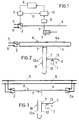
- the device for controlling a hydrostatic drive 1, which acts as a working cylinder has a switching valve 2, which has a suitable Drive 3 is actuated periodically.
- This switching valve 2 connects a resonance tube 4 alternately with a hydraulic medium supply line 5 and one Return line 6 to a prestressed hydraulic fluid tank.
- the length of the Resonance tube 4 corresponds to an integer multiple of the wavelength of the pressure waves of the hydraulic medium that form in the resonance tube 4 due to the pressure pulses resulting from the actuation of the switching valve Spread over the length of the resonance tube 4.
- the resonance tube 4 also forms a fixed reflection end for these pressure waves standing under resonance conditions in the resonance tube 4 different pressure waves Order with vibration nodes, in which the through these nodes going pressure waves have no amplitude, so that by a Pressure outlet 7 in the area of such a node, the associated him Pressure waves are suppressed and the connected to this pressure outlet 7 Actuator 1 is subjected to a working pressure, which accordingly is less subject to fluctuations.
- the commute to work Pressure output 7 connected drive 1 has the resonance conditions no influence in the resonance tube 4, which creates simple control conditions, because of the switching times of the switching valve that determine the pressure pulse width 2 the effective value at a switching frequency that is matched to the resonance frequency the working pressure at the pressure outlet 7 between any one of the pressure in the hydraulic medium supply line 5 corresponding maximum pressure and a minimum pressure corresponding to the pressure in the return line 6 is set can be.
- the factors influencing the resonance conditions cannot always be considered be viewed constantly.
- the toughness and the Compressibility of the hydraulic fluid with the fluctuations Temperature so that the device to the changing resonance conditions must be adjusted if the highest possible efficiency is desired becomes.
- This adjustment can be made comparatively simply by a tracking the switching frequency of the switching valve 2 can be reached, as shown in FIG. 1 is indicated schematically.
- the drive 3 for the switching valve 2 controlled by a control device 8, the possible shift of a vibration node monitored.
- Belt filters 10 can be used to relocate vibration nodes on the specified one Pressure amplitudes occurring at the node of the vibration node assigned pressure waves detected and for controlling the switching valve drive 3 in the sense of tracking the switching frequency to the resonance frequency be exploited.
- the band filter 10 can be set to the respective switching frequency of the switching valve can be matched, which in Fig. 1 by a Control line 11 between the switching valve drive 3 and the band filter 10 is illustrated.
- the higher order pressure waves can be provided in general particularly favorable conditions in the area of a vibration node the fundamental wave of the pressure vibrations, i.e. in the longitudinal center of the Resonant tube 4.
- the fundamental wave and the pressure harmonics suppressed with an odd atomic number at the pressure outlet 7.
- the pressure output 7 of the Resonance tube 4 an additional resonance tube 12 and optionally in further sequence additional resonance tubes 13 are connected, namely each at the pressure outlet 7 of the immediately upstream resonance tube. If the pressure outlet 7 is arranged in the center, the resonance pipes each designed with half the length of the upstream resonance tube, as shown in Figs. 2 to 4.
- FIG. 3 Another possibility is a fixed reflection end for the main resonator A. form, according to FIG. 3, is at the end of the resonance tube 4 to To provide switching valve 2 counter-operated switching valve 2a, so that Resonance pipe 4 on one side with the hydraulic medium supply line 5 and is connected at the other end to the return line 6 and vice versa, and with the respective resonance frequency.
- the resonance tubes can be made orthotropic, a correspondingly lower rigidity is required in the axial direction, so that the tubular body is carried along by the hydraulic fluid in the axial direction can be.
- the resonance pipes consist of corrugated tubes, which is illustrated in FIG. 5 for the main resonator A. is. In such a case, of course, must be ensured be that the pipe ends are held in place, which for reasons of clarity is not shown in detail.
- the connection of the pressure outlet 7 must however permit a corresponding pipe movement.
- the pressure outlet 7 is formed by a connecting sleeve 14, which from Resonance tube 4 is penetrated axially. Since the connector sleeve 14 Surrounds resonance tube 4 with a radial distance, the seal is through Ring cuffs 15 reached, the Relatiwerschieb between tube and Allow sleeve.
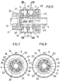
- FIGS. 6 to 8 On Switch valve that meets these requirements is shown schematically in FIGS. 6 to 8 shown. It essentially consists of a resonant tube 4 Housing 16 in which a rotary piston coaxial with the resonance tube 4 17 is rotatably mounted, the two axially arranged one behind the other Intermediate chambers 18 and 19 of the housing 16 and in the area of both Has annular chambers 18, 19 through-openings 20 forming control edges, which cooperate with through openings 21 of the resonance tube 4.
- a rotationally adjustable control sleeve 22 mounted in the housing 16 with Through openings 23 and control edges 24 formed by these is provided.
- This control sleeve 22 can be adjusted via a ring gear 25.
- the through openings 20 of the rotary piston 17 are in the opposite direction in the area of the annular chamber 19 connected to the return line 6 through the associated control edges 24 opened until they come out of the area of the passage openings 21 of the resonance tube 4 arrive, whereby an alternating Connection of the resonance tube 4 to the hydraulic medium supply line 5 and to the return line 6 is ensured.
- the switching times are over the Determined rotational position of the control sleeve 22 relative to the resonance tube 4, while the switching frequency for a given number of over the scope distributed openings only from the speed of the rotary piston 17th depends. It can therefore be the pulse width at a set switching frequency by rotating the control sleeve 22 to control the hydrostatic Drive 1 can be adjusted as desired, which is in a corresponding Changes in the working pressure at the pressure outputs 7 noticeable.
- annular chambers 18 are advantageous for this purpose and 19, in which pressure-elastic bodies are inserted for this purpose can, for example with compressed gas, e.g. B. nitrogen, filled ring tubes 27, which are indicated by dash-dotted lines in FIG. 6.
- compressed gas e.g. B. nitrogen
Landscapes
- Engineering & Computer Science (AREA)
- Mechanical Engineering (AREA)
- General Engineering & Computer Science (AREA)
- Analytical Chemistry (AREA)
- Physics & Mathematics (AREA)
- Fluid Mechanics (AREA)
- Chemical & Material Sciences (AREA)
- Fluid-Pressure Circuits (AREA)
- Valve Device For Special Equipments (AREA)
- Vehicle Body Suspensions (AREA)
- Hydraulic Clutches, Magnetic Clutches, Fluid Clutches, And Fluid Joints (AREA)
- Reciprocating Pumps (AREA)
- Apparatuses For Generation Of Mechanical Vibrations (AREA)
Description
- Fig. 1
- eine erfindungsgemäße Vorrichtung zum Steuern eines hydrostatischen Antriebes in einem einfachen Blockschaltbild,
- Fig. 2
- ein Blockschaltbild einer erfindungsgemäßen Vorrichtung mit einem Haupt- und zwei Nebenresonatoren,
- Fig. 3
- eine der Fig. 2 entsprechende Vorrichtung in einer Konstruktionsvariante,
- Fig. 4
- eine weitere Ausführungsform einer erfindungsgemäßen Vorrichtung,
- Fig. 5
- einen Resonator mit parallel geschalteten orthotropen Resonanzrohren in einem vereinfachten Axialschnitt,
- Fig. 6
- einen vereinfachten Axialschnitt durch ein Schaltventil,
- Fig. 7
- einen Schnitt nach der Linie VII-VII der Fig. 6 und
- Fig. 8
- einen Schnitt nach der Linie VIII-VIII der Fig. 6.
Claims (9)
- Vorrichtung zum Steuern eines hydrostatischen Antriebes (1) mit einem periodisch betätigbaren Schaltventil (2), das ein mit dem hydrostatischen Antrieb (1) fluidisch verbundenes Resonanzrohr (4) zur Ausbildung stehender Druckwellen des Hydraulikmittels unter Resonanzbedingungen abwechselnd an eine Druckmittelversorgungsleitung (5) und an eine Rückleitung (6) anschließt, dadurch gekennzeichnet, daß das Resonanzrohr (4) einen mit dem hydrostatischen Antrieb (1) fluidisch verbundenen Druckausgang (7) in einem Schwingungsknoten der stehenden Druckwellen aufweist und daß die Schaltzeiten des Schaltventiles (2) bei gleichbleibender Schaltfrequenz steuerbar sind.
- Vorrichtung nach Anspruch 1, dadurch gekennzeichnet, daß das an das Schaltventil (2) angeschlossene Resonanzrohr (4) einen Hauptresonator (A) bildet, an dessen Druckausgang (7) wenigstens ein Nebenresonator (B) mit einem Resonanzrohr (12) anschließt, das wiederum einen mit dem hydrostatischen Antrieb (1) fluidisch verbundenen Druckausgang (7) in einem Schwingungsknoten der sich in diesem Resonanzrohr (12) ausbildenden stehenden Druckwellen aufweist, und daß das Resonanzrohr (4) des Hauptresonators (A) entweder mit einem zusätzlichen Resonanzrohr (4a) parallelgeschaltet oder beiderends über gegensinnig betätigbare Schaltventile (2, 2a) mit der Druckmittelversorgungsleitung (5) und der Rückleitung (6) verbindbar ist.
- Vorrichtung nach Anspruch 2, dadurch gekennzeichnet, daß beim Vorsehen von wenigstens zwei Nebenresonatoren (B, C) diese jeweils an den Druckausgang (7) des vorhergehenden Resonators (A, B) angeschlossen sind und mit Ausnahme des ausgangsseitigen Nebenresonators (C) aus einer Parallelschaltung von zumindest zwei Resonanzrohren (12, 12a) bestehen, von denen eines den Druckausgang (7) zum Anschluß des nachfolgenden Nebenresonators (C) aufweist.
- Vorrichtung nach einem der Ansprüche 1 bis 3, dadurch gekennzeichnet, daß
bei einer Parallelschaltung zweier Resonanzrohre (4, 4a; 12, 12a) diese einander koaxial umschließen. - Vorrichtung nach einem der Ansprüche 1 bis 4, dadurch gekennzeichnet, daß dem Schaltventil (2) eine Regeleinrichtung (8) zum Nachführen der Schaltfrequenz an die sich allenfalls ändernde Resonanzfrequenz des unmittelbar an das Steuerventil (2) angeschlossenen Resonators (A) zugeordnet ist.
- Vorrichtung nach einem der Ansprüche 1 bis 5, dadurch gekennzeichnet, daß das Schaltventil (2) als Rotationskolbenventil mit einem das Resonanzrohr (4) koaxial umschließenden Rotationskolben (17) ausgebildet ist, der in einem Gehäuse (16) axial hintereinander angeordnete, einerseits mit der Hydraulikmittelversorgungsleitung (5) und anderseits mit der Rückleitung (6) verbundene Ringkammern (18, 19) durchsetzt und im Bereich dieser Ringkammern (18, 19) Steuerkanten bildende, mit Durchtrittsöffnungen (21) des Resonanzrohres (4) zusammenwirkende Durchtrittsöffnungen (20) aufweist, deren Freigabe durch eine drehverstellbare Steuerhülse (22) mit Steuerkanten (24) für die Schaltzeiten steuerbar ist.
- Vorrichtung nach Anspruch 6, dadurch gekennzeichnet, daß in den Ringkammern (18, 19) des Gehäuses (16) des Schaltventiles (2) druckelastische Körper, vorzugsweise mit einem Druckgas gefüllte Schläuche ((27), vorgesehen sind.
- Vorrichtung nach einem der Ansprüche 1 bis 7, dadurch gekennzeichnet, daß der Rohrkörper des Resonanzrohres (4) bzw. der Resonanzrohre (4, 4a, 12, 12a, 13) orthotrop mit einer gegenüber der axialen Richtung größeren Steifigkeit in Umfangsrichtung ausgebildet ist.
- Vorrichtung nach Anspruch 8, dadurch gekennzeichnet, daß der Rohrkörper des Resonanzrohres (4) bzw. der Resonanzrohre (4, 4a, 12, 12a, 13) aus einem Wellrohr besteht.
Applications Claiming Priority (4)
| Application Number | Priority Date | Filing Date | Title |
|---|---|---|---|
| AT169/95 | 1995-02-01 | ||
| AT16995 | 1995-02-01 | ||
| AT0016995A AT403219B (de) | 1995-02-01 | 1995-02-01 | Vorrichtung zum ansteuern eines hydrostatischen antriebes |
| PCT/AT1996/000015 WO1996023980A2 (de) | 1995-02-01 | 1996-01-31 | Vorrichtung zum ansteuern eines hydrostatischen antriebes |
Publications (2)
| Publication Number | Publication Date |
|---|---|
| EP0807212A2 EP0807212A2 (de) | 1997-11-19 |
| EP0807212B1 true EP0807212B1 (de) | 2001-04-11 |
Family
ID=3483410
Family Applications (1)
| Application Number | Title | Priority Date | Filing Date |
|---|---|---|---|
| EP96901186A Expired - Lifetime EP0807212B1 (de) | 1995-02-01 | 1996-01-31 | Vorrichtung zum ansteuern eines hydrostatischen antriebes |
Country Status (6)
| Country | Link |
|---|---|
| US (1) | US5974800A (de) |
| EP (1) | EP0807212B1 (de) |
| AT (2) | AT403219B (de) |
| CZ (1) | CZ283346B6 (de) |
| DE (1) | DE59606770D1 (de) |
| WO (1) | WO1996023980A2 (de) |
Families Citing this family (6)
| Publication number | Priority date | Publication date | Assignee | Title |
|---|---|---|---|---|
| ATA150995A (de) * | 1995-09-12 | 1997-12-15 | Rudolf Scheidl | Vorrichtung zum ansteuern eines hydrostatischen antriebes |
| DE19842534A1 (de) | 1998-08-01 | 2000-02-03 | Mannesmann Rexroth Ag | Hydrostatisches Antriebssystem für eine Spritzgießmaschine und Verfahren zum Betreiben eines solchen Antriebssystems |
| US9121397B2 (en) | 2010-12-17 | 2015-09-01 | National Oilwell Varco, L.P. | Pulsation dampening system for a reciprocating pump |
| US11639728B2 (en) | 2019-04-07 | 2023-05-02 | Resonance Technology International Inc. | Spool valve and piston geometry to reduce cavitation effects in a linear actuator |
| US11338326B2 (en) | 2019-04-07 | 2022-05-24 | Resonance Technology International Inc. | Single-mass, one-dimensional resonant driver |
| CN121429684B (zh) * | 2025-12-29 | 2026-03-24 | 四川省能源地质调查研究所 | 复杂地质下液压钻机钻进参数自修正系统及方法 |
Family Cites Families (14)
| Publication number | Priority date | Publication date | Assignee | Title |
|---|---|---|---|---|
| US3020720A (en) * | 1957-02-20 | 1962-02-13 | Albert K Spalding | Method and means for producing hydraulic vibrations |
| FR1407445A (fr) * | 1964-09-03 | 1965-07-30 | Pic Sa | Procédé et dispositif pour la transformation des différences de pression constante en pression pulsée |
| US3541782A (en) * | 1968-10-24 | 1970-11-24 | Shell Oil Co | Control for resonant vibrating system |
| US3835810A (en) * | 1969-09-04 | 1974-09-17 | Energy Sciences Inc | Pressure wave mixing |
| US3741073A (en) * | 1971-01-29 | 1973-06-26 | Moog Inc | Hysteretic equalization in redundant electrically operated fluid powered servopositioning apparatus |
| EP0006833B1 (de) * | 1978-07-03 | 1983-09-14 | Mats Olsson Konsult Ab | Niederfrequenz Schallgeber |
| DE2931797C2 (de) * | 1979-08-04 | 1985-08-14 | Kernforschungszentrum Karlsruhe Gmbh, 7500 Karlsruhe | Steuervorrichtung für die Pulsationsbewegungen einer Pulskolonne |
| DE3314392A1 (de) * | 1983-04-21 | 1984-10-25 | Sieke, Helmut, Dipl.-Ing., 6200 Wiesbaden | Verfahren und vorrichtung zur stufenlosen steuerung der geschwindigkeit und/oder beschleunigung von hydraulisch angetriebenen arbeitswerkzeugen |
| EP0229210A1 (de) * | 1986-01-16 | 1987-07-22 | MOOG GmbH | Steuerschaltung für eine hydrostatisch gelagerte Stützwalze |
| US4702315A (en) * | 1986-08-26 | 1987-10-27 | Bodine Albert G | Method and apparatus for sonically stimulating oil wells to increase the production thereof |
| EP0366686B1 (de) * | 1987-06-24 | 1995-02-01 | BIES, David Alan | Schwingungsenergieerzeuger |
| GB8823245D0 (en) * | 1988-10-04 | 1989-04-19 | British Aerospace | Flextensional transducer |
| NL8902546A (nl) * | 1989-10-13 | 1991-05-01 | Pieter Faber | Betonpompinrichting. |
| DE4116842A1 (de) * | 1991-05-23 | 1992-11-26 | Bw Hydraulik Gmbh | Einrichtung zur hubbegrenzung eines hydraulikzylinders |
-
1995
- 1995-02-01 AT AT0016995A patent/AT403219B/de not_active IP Right Cessation
-
1996
- 1996-01-31 WO PCT/AT1996/000015 patent/WO1996023980A2/de not_active Ceased
- 1996-01-31 DE DE59606770T patent/DE59606770D1/de not_active Expired - Lifetime
- 1996-01-31 EP EP96901186A patent/EP0807212B1/de not_active Expired - Lifetime
- 1996-01-31 US US08/894,494 patent/US5974800A/en not_active Expired - Fee Related
- 1996-01-31 CZ CZ972285A patent/CZ283346B6/cs not_active IP Right Cessation
- 1996-01-31 AT AT96901186T patent/ATE200559T1/de not_active IP Right Cessation
Also Published As
| Publication number | Publication date |
|---|---|
| EP0807212A2 (de) | 1997-11-19 |
| ATA16995A (de) | 1997-04-15 |
| DE59606770D1 (de) | 2001-05-17 |
| ATE200559T1 (de) | 2001-04-15 |
| CZ228597A3 (en) | 1997-11-12 |
| WO1996023980A3 (de) | 1996-09-26 |
| US5974800A (en) | 1999-11-02 |
| CZ283346B6 (cs) | 1998-03-18 |
| WO1996023980A2 (de) | 1996-08-08 |
| AT403219B (de) | 1997-12-29 |
Similar Documents
| Publication | Publication Date | Title |
|---|---|---|
| DE4318553C2 (de) | Adaptiver hydropneumatischer Pulsationsdämpfer | |
| DE3713997C2 (de) | Hydropneumatischer Verbundzylinder | |
| DE69217301T2 (de) | Verfahren und Vorrichtung zum Steuern ein Flüssigkeitsströmung | |
| EP1715189B1 (de) | Schalldämpfer ausgebildet und bestimmt für einen Kompressor | |
| DE1475701B2 (de) | Interferenz-Geräuschdämpfer | |
| EP0825348A1 (de) | Druckverstärker für Fluide, insbesondere für Hydraulikflüssigkeiten | |
| EP1775495A2 (de) | Schwingungsdämpfer mit verstellbarer Dämpfkraft | |
| DE2256072C3 (de) | Anordnung zur Begrenzung der Reaktionskraft bei hydraulischen Servolenkeinrichtungen | |
| DE2343552A1 (de) | Elektrohydraulisches servoventil | |
| DE1576088B2 (de) | Schnellentlastungsventil fuer hydraulische kraftzylinder | |
| EP0807212B1 (de) | Vorrichtung zum ansteuern eines hydrostatischen antriebes | |
| DE10015051A1 (de) | Vorrichtung zur Verringerung von Druckpulsationen | |
| DE1650251A1 (de) | Orgelpfeifen-Stroemungsmitteloszillator | |
| WO2015120999A1 (de) | Ventil für einen schwingungsdämpfer, schwingungsdämpfer sowie kraftfahrzeug | |
| EP2756197B1 (de) | Fluidventilanordnung mit einem bistabilen fluidventil | |
| EP0850364B1 (de) | Vorrichtung zum ansteuern eines hydrostatischen antriebes | |
| AT501573B1 (de) | Hydraulische vorrichtung mit zumindest einem druckspeicher | |
| WO2004018120A1 (de) | Haupt- bzw. presszylinder einer rohr- und strangpresse | |
| DE2161794C3 (de) | Drucksteuereinrichtung für Hydraulische Systeme | |
| AT408899B (de) | Dämpfungsanordnung für fluidsysteme | |
| DE19820102B4 (de) | Oszillier-Zylinder | |
| DE102018217820A1 (de) | Hydraulische Steueranordnung und hydraulische Achse | |
| DE1528394A1 (de) | Hydraulischer Kolbenmotor | |
| DE69301012T2 (de) | Pneumatischer Drehantrieb mit erhöhtem Anlaufmoment | |
| DE202017005489U1 (de) | Hydraulikeinheit eines Drehpfluges |
Legal Events
| Date | Code | Title | Description |
|---|---|---|---|
| PUAI | Public reference made under article 153(3) epc to a published international application that has entered the european phase |
Free format text: ORIGINAL CODE: 0009012 |
|
| 17P | Request for examination filed |
Effective date: 19970719 |
|
| AK | Designated contracting states |
Kind code of ref document: A2 Designated state(s): AT DE FR GB IT |
|
| 17Q | First examination report despatched |
Effective date: 19971124 |
|
| RAP1 | Party data changed (applicant data changed or rights of an application transferred) |
Owner name: MANNESMANN REXROTH AKTIENGESELLSCHAFT |
|
| GRAG | Despatch of communication of intention to grant |
Free format text: ORIGINAL CODE: EPIDOS AGRA |
|
| GRAG | Despatch of communication of intention to grant |
Free format text: ORIGINAL CODE: EPIDOS AGRA |
|
| GRAH | Despatch of communication of intention to grant a patent |
Free format text: ORIGINAL CODE: EPIDOS IGRA |
|
| GRAH | Despatch of communication of intention to grant a patent |
Free format text: ORIGINAL CODE: EPIDOS IGRA |
|
| GRAA | (expected) grant |
Free format text: ORIGINAL CODE: 0009210 |
|
| AK | Designated contracting states |
Kind code of ref document: B1 Designated state(s): AT DE FR GB IT |
|
| REF | Corresponds to: |
Ref document number: 200559 Country of ref document: AT Date of ref document: 20010415 Kind code of ref document: T |
|
| REF | Corresponds to: |
Ref document number: 59606770 Country of ref document: DE Date of ref document: 20010517 |
|
| ITF | It: translation for a ep patent filed | ||
| GBT | Gb: translation of ep patent filed (gb section 77(6)(a)/1977) |
Effective date: 20010713 |
|
| ET | Fr: translation filed | ||
| REG | Reference to a national code |
Ref country code: GB Ref legal event code: IF02 |
|
| PLBE | No opposition filed within time limit |
Free format text: ORIGINAL CODE: 0009261 |
|
| STAA | Information on the status of an ep patent application or granted ep patent |
Free format text: STATUS: NO OPPOSITION FILED WITHIN TIME LIMIT |
|
| 26N | No opposition filed | ||
| PGFP | Annual fee paid to national office [announced via postgrant information from national office to epo] |
Ref country code: FR Payment date: 20021128 Year of fee payment: 8 |
|
| PG25 | Lapsed in a contracting state [announced via postgrant information from national office to epo] |
Ref country code: FR Free format text: LAPSE BECAUSE OF NON-PAYMENT OF DUE FEES Effective date: 20040930 |
|
| REG | Reference to a national code |
Ref country code: FR Ref legal event code: ST |
|
| PGFP | Annual fee paid to national office [announced via postgrant information from national office to epo] |
Ref country code: IT Payment date: 20060131 Year of fee payment: 11 |
|
| PGFP | Annual fee paid to national office [announced via postgrant information from national office to epo] |
Ref country code: GB Payment date: 20070123 Year of fee payment: 12 |
|
| GBPC | Gb: european patent ceased through non-payment of renewal fee |
Effective date: 20080131 |
|
| PG25 | Lapsed in a contracting state [announced via postgrant information from national office to epo] |
Ref country code: GB Free format text: LAPSE BECAUSE OF NON-PAYMENT OF DUE FEES Effective date: 20080131 |
|
| PG25 | Lapsed in a contracting state [announced via postgrant information from national office to epo] |
Ref country code: IT Free format text: LAPSE BECAUSE OF NON-PAYMENT OF DUE FEES Effective date: 20070131 |
|
| PGFP | Annual fee paid to national office [announced via postgrant information from national office to epo] |
Ref country code: AT Payment date: 20100120 Year of fee payment: 15 |
|
| PGFP | Annual fee paid to national office [announced via postgrant information from national office to epo] |
Ref country code: DE Payment date: 20100324 Year of fee payment: 15 |
|
| PG25 | Lapsed in a contracting state [announced via postgrant information from national office to epo] |
Ref country code: AT Free format text: LAPSE BECAUSE OF NON-PAYMENT OF DUE FEES Effective date: 20110131 |
|
| REG | Reference to a national code |
Ref country code: DE Ref legal event code: R119 Ref document number: 59606770 Country of ref document: DE Effective date: 20110802 |
|
| PG25 | Lapsed in a contracting state [announced via postgrant information from national office to epo] |
Ref country code: DE Free format text: LAPSE BECAUSE OF NON-PAYMENT OF DUE FEES Effective date: 20110802 |