EP0807035B1 - Dispositif d'essuyage pour une vitre de vehicule automobile - Google Patents
Dispositif d'essuyage pour une vitre de vehicule automobile Download PDFInfo
- Publication number
- EP0807035B1 EP0807035B1 EP96941080A EP96941080A EP0807035B1 EP 0807035 B1 EP0807035 B1 EP 0807035B1 EP 96941080 A EP96941080 A EP 96941080A EP 96941080 A EP96941080 A EP 96941080A EP 0807035 B1 EP0807035 B1 EP 0807035B1
- Authority
- EP
- European Patent Office
- Prior art keywords
- bearing
- spindle
- rotation
- axis
- spherical
- Prior art date
- Legal status (The legal status is an assumption and is not a legal conclusion. Google has not performed a legal analysis and makes no representation as to the accuracy of the status listed.)
- Expired - Lifetime
Links
Images

Classifications
-
- B—PERFORMING OPERATIONS; TRANSPORTING
- B60—VEHICLES IN GENERAL
- B60S—SERVICING, CLEANING, REPAIRING, SUPPORTING, LIFTING, OR MANOEUVRING OF VEHICLES, NOT OTHERWISE PROVIDED FOR
- B60S1/00—Cleaning of vehicles
- B60S1/02—Cleaning windscreens, windows or optical devices
- B60S1/04—Wipers or the like, e.g. scrapers
- B60S1/32—Wipers or the like, e.g. scrapers characterised by constructional features of wiper blade arms or blades
- B60S1/34—Wiper arms; Mountings therefor
- B60S1/3486—Means to allow blade to follow curvature of the screen (i.e. rotation along longitudinal axis of the arm)
-
- B—PERFORMING OPERATIONS; TRANSPORTING
- B60—VEHICLES IN GENERAL
- B60S—SERVICING, CLEANING, REPAIRING, SUPPORTING, LIFTING, OR MANOEUVRING OF VEHICLES, NOT OTHERWISE PROVIDED FOR
- B60S1/00—Cleaning of vehicles
- B60S1/02—Cleaning windscreens, windows or optical devices
- B60S1/04—Wipers or the like, e.g. scrapers
- B60S1/32—Wipers or the like, e.g. scrapers characterised by constructional features of wiper blade arms or blades
- B60S1/34—Wiper arms; Mountings therefor
- B60S1/3488—Means for mounting wiper arms onto the vehicle
- B60S1/3493—Means for mounting the wiper shaft in the wiper bearing
-
- F—MECHANICAL ENGINEERING; LIGHTING; HEATING; WEAPONS; BLASTING
- F16—ENGINEERING ELEMENTS AND UNITS; GENERAL MEASURES FOR PRODUCING AND MAINTAINING EFFECTIVE FUNCTIONING OF MACHINES OR INSTALLATIONS; THERMAL INSULATION IN GENERAL
- F16C—SHAFTS; FLEXIBLE SHAFTS; ELEMENTS OR CRANKSHAFT MECHANISMS; ROTARY BODIES OTHER THAN GEARING ELEMENTS; BEARINGS
- F16C23/00—Bearings for exclusively rotary movement adjustable for aligning or positioning
- F16C23/10—Bearings, parts of which are eccentrically adjustable with respect to each other
-
- B—PERFORMING OPERATIONS; TRANSPORTING
- B60—VEHICLES IN GENERAL
- B60S—SERVICING, CLEANING, REPAIRING, SUPPORTING, LIFTING, OR MANOEUVRING OF VEHICLES, NOT OTHERWISE PROVIDED FOR
- B60S1/00—Cleaning of vehicles
- B60S1/02—Cleaning windscreens, windows or optical devices
- B60S1/04—Wipers or the like, e.g. scrapers
- B60S1/32—Wipers or the like, e.g. scrapers characterised by constructional features of wiper blade arms or blades
- B60S1/34—Wiper arms; Mountings therefor
- B60S1/3425—Constructional aspects of the arm
- B60S1/3443—Wiper shafts
-
- F—MECHANICAL ENGINEERING; LIGHTING; HEATING; WEAPONS; BLASTING
- F16—ENGINEERING ELEMENTS AND UNITS; GENERAL MEASURES FOR PRODUCING AND MAINTAINING EFFECTIVE FUNCTIONING OF MACHINES OR INSTALLATIONS; THERMAL INSULATION IN GENERAL
- F16C—SHAFTS; FLEXIBLE SHAFTS; ELEMENTS OR CRANKSHAFT MECHANISMS; ROTARY BODIES OTHER THAN GEARING ELEMENTS; BEARINGS
- F16C2326/00—Articles relating to transporting
- F16C2326/01—Parts of vehicles in general
- F16C2326/09—Windscreen wipers, e.g. pivots therefore
-
- Y—GENERAL TAGGING OF NEW TECHNOLOGICAL DEVELOPMENTS; GENERAL TAGGING OF CROSS-SECTIONAL TECHNOLOGIES SPANNING OVER SEVERAL SECTIONS OF THE IPC; TECHNICAL SUBJECTS COVERED BY FORMER USPC CROSS-REFERENCE ART COLLECTIONS [XRACs] AND DIGESTS
- Y10—TECHNICAL SUBJECTS COVERED BY FORMER USPC
- Y10T—TECHNICAL SUBJECTS COVERED BY FORMER US CLASSIFICATION
- Y10T74/00—Machine element or mechanism
- Y10T74/18—Mechanical movements
- Y10T74/18056—Rotary to or from reciprocating or oscillating
- Y10T74/18184—Crank, pitman, and lever
-
- Y—GENERAL TAGGING OF NEW TECHNOLOGICAL DEVELOPMENTS; GENERAL TAGGING OF CROSS-SECTIONAL TECHNOLOGIES SPANNING OVER SEVERAL SECTIONS OF THE IPC; TECHNICAL SUBJECTS COVERED BY FORMER USPC CROSS-REFERENCE ART COLLECTIONS [XRACs] AND DIGESTS
- Y10—TECHNICAL SUBJECTS COVERED BY FORMER USPC
- Y10T—TECHNICAL SUBJECTS COVERED BY FORMER US CLASSIFICATION
- Y10T74/00—Machine element or mechanism
- Y10T74/18—Mechanical movements
- Y10T74/18856—Oscillating to oscillating
-
- Y—GENERAL TAGGING OF NEW TECHNOLOGICAL DEVELOPMENTS; GENERAL TAGGING OF CROSS-SECTIONAL TECHNOLOGIES SPANNING OVER SEVERAL SECTIONS OF THE IPC; TECHNICAL SUBJECTS COVERED BY FORMER USPC CROSS-REFERENCE ART COLLECTIONS [XRACs] AND DIGESTS
- Y10—TECHNICAL SUBJECTS COVERED BY FORMER USPC
- Y10T—TECHNICAL SUBJECTS COVERED BY FORMER US CLASSIFICATION
- Y10T74/00—Machine element or mechanism
- Y10T74/21—Elements
- Y10T74/2173—Cranks and wrist pins
- Y10T74/2179—Adjustable
Definitions
- the invention relates to a wiping device of a motor vehicle window.
- the invention relates more particularly to a wiping device for a vehicle window automobile, of the type in which a wiper extends longitudinally parallel to the plane general of the window to be wiped, of the type in which the wiper is mounted at the upper end of a rotary sweep drive shaft alternate whose axis is substantially perpendicular in the general plane of the glass, of the type in which the drive shaft is rotatably mounted in a fixed bearing with respect to the vehicle, and of the type in which the drive shaft is driven in rotation by a crank which extends in a plane substantially perpendicular to the axis of the tree and which is connected by a linkage to a geared motor, the drive shaft being mounted at rotation in the bearing by at least one ball joint with the inclination of its axis which is intended to vary from the plane of the glass when rotated around its axis.
- a wiping device of this type is known of document FR-A-2.625.715.
- Such a device makes it possible to sweep the window to using a squeegee made of flexible elastomer material which is pressed against the windshield by a broom wiper carried by the wiper.
- motor vehicle windows and in particular windshields, are generally curved so it is necessary that the broom wiper has an articulated structure which requires the squeegee to be in contact throughout length with glass.
- the articulated structure of the broom allows in addition to ensuring that the contact pressure is substantially uniform over the entire length of the squeegee, and for this purpose it is deformable in a plane which is substantially perpendicular to the wiping glass and the articulated structure maintains, using claws, the squeegee in its plan deformation.
- the wiper blade scans the window in its sweeping movement alternating rotary
- the deformation plane of its articulated structure does not remain rigorously perpendicular to the plane of the glass to be wiped, curves the window, so that the squeegee is in contact with the glass at an angle which varies depending on the position of the wiper.
- a particularly unfavorable case is the case where, being a vehicle windshield automotive, the wiper is designed to wipe a curved side end towards the rear of the windshield arriving substantially parallel to the side pillar of the windscreen.
- the tilt angle of the squeegee in relation to the glass is then important and can affect the effectiveness of the wiper in this area.
- the invention proposes a windscreen wiper type seen previously, characterized in that the tree drive is rotatably mounted in the bearing by two ball joints, in that one at less of the ball joints is arranged to so that its center of rotation is offset by in relation to the axis of the drive shaft, and in this that the shaft is integral in rotation with a ball joint internal of the eccentric joint.
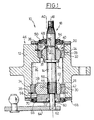
- the bearing 10 includes a bearing body 12 substantially tubular, of axis A0, which is arranged substantially perpendicular to the internal face of a body panel (not shown) which is usually located at the lower edge of the glass.
- a drive shaft 14, of axis A1 is axially rotatably mounted in the internal bore 16 of the bearing body 12 and has one end upper 18, which protrudes through an orifice the body panel on the outside of the vehicle, and on which a wiper is intended to be fixed.
- the shaft 14 is mounted in the bearing body 12 by two ball joints, respectively upper 20 and lower 22.
- Each ball joint 20, 22 comprises an outer ring 24, 26 for guiding and positioning which is fixed in the internal bore 16 of the bearing body 12.
- the outer ring 24, 26 is of general shape annular and has an external lateral surface 28, 30 cylindrical so as to be received in a corresponding cylindrical housing formed in the internal bore 16 of the bearing body 12.
- the outer ring 24, 26 of each of the ball joints 20, 22 is axially fixed in its housing correspondent, in a first direction in support against a radial shoulder face 32, 34 produced integral with the bearing body 12 and, in the opposite direction, by an elastic ring 36, 38.
- Each outer ring 24, 26 has a internal spherical surface 37, 39 in which is mounted an internal ball joint 40, 42 which is susceptible rotate around the center C1, C2 of the surface internal spherical 37, 39 of the outer ring 24, 26.
- the drive shaft 14 is mounted eccentrically in the internal ball joint 42 of the lower articulation 22 of so that its axis A1 does not pass through the center C2 of the joint 22.
- the drive shaft 14 is mounted in the internal ball joint 42 by a grooved portion 44 which prevents relative rotation of the shaft 14 by compared to the internal patella 42.
- the tree drive 14 protrudes at both ends axial 46, 68 of the bearing body 12, and it is provided for this purpose sealing means which transversely close the bearing 12.
- a flexible membrane annular seal has been arranged 48, an external periphery 50 of which is fixed to the upper axial end 46 of the bearing body 12 and of which an internal periphery 54 carries tightly on the drive shaft 14.
- the internal ball joint 42 of the joint lower 22 has an axial extension cylindrical 56, which extends downward beyond the lower end 68 of the bearing body 12, and which is provided with a cylindrical passage 58 through which protrudes a free end 60 of the shaft 14 which is intended to be connected, via from a drive square 62, to a crank 64 which extends perpendicular to the axis A1.
- Crank 64 is actuated by a gearmotor (not shown) with interposition a control linkage (not shown).
- a flexible membrane annular seal 66 which is fixed by an external periphery on the end lower 68 of the bearing body 12 and which carries, by an internal periphery, on the surface external cylindrical 70 of the extension 56 of the internal ball 42.
- a seal 72 is arranged between the free end 60 of the shaft 14 and the axial extension 56 of the internal ball joint 42.
- the internal ball 40 of the upper joint 20 is immobilized axially on the shaft 14 between a external radial collar 74 of the shaft 14 and a ring split elastic 76 which is mounted in a groove annular 78 of the shaft 14.
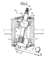
- Figure 3 is a view similar to that of Figure 1 in which the drive shaft has rotated 180 ° around its axis A1 under the effect of the crank 64, itself actuated by the linkage and gearmotor.
- the center C2 of the internal patella not being located on the axis A1 of the shaft 14, the internal ball joint 42 imposes on the shaft 14 a rotational movement around the center C2 which is fixed relative to the bearing body 12 and therefore fixed relative to the vehicle.
- the shaft 14 is animated by a movement of rotation around the center C1 of the internal patella 40 of the upper joint 20 but the center C1 coincides, in the embodiment, with the axis A1 of the tree 14.
- the shaft 14 is animated by a movement of rotation around the line connecting the centers C1, C2 of the joints 20, 22 so that the shaft 14 describes in space a conical movement which induces a variation of the orientation of the axis A1 of the shaft 14 relative to the axis A0 of the bearing housing 12 which is fixed relative to the vehicle.
- the inclination of axis A1 with respect to its initial position is maximum for a rotation of 180 ° from shaft 14, as illustrated in Figure 3, but, in the case of an implantation on a motor vehicle, the angle of rotation maximum may be lower.
- the membrane seals 48, 66 allow, by deforming, to maintain the sealing of the bearing 10 whatever the position of the shaft 14.
- a wiper attached to the upper end 18 of the shaft 14 is not only animated by a movement of scan around the axis A1 of the tree but it also pivots around the center C1 of the upper joint 20, which changes its orientation towards the general direction of the body panel and glass.
- the wiper tends to rotate around its longitudinal axis during its sweep stroke.
- the maximum value of the swivel angle varies depending on the relationship between the distance separating the two centers C1, C2 of the joints 20, 22 and the eccentricity of the shaft 14 in the internal ball joint 42 of the lower joint 22.
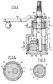
- Figures 4 to 6 show a second embodiment of the invention in which the crank 64 is arranged on the shaft 14, not at its lower end, but axially between the upper end 18 of the shaft 14 and the upper end 46 of the bearing body 12.
- the shaft 14 does not protrude at the two ends of the body bearing 12 so that the axial end lower 68 of the bearing 12 is then closed by a transverse flange 80.
- the end lower 82 of the shaft 14 is not grooved but is provided with an axial groove 84, which opens into the axial face 85 of the lower end of the shaft 14, and which cooperates with a radial pin 86 mounted in the internal ball joint 42 of the joint lower 22 to couple the shaft 14 in rotation and the internal patella 42.
- the internal ball joint 40 of the upper articulation 20 is fixed axially on the shaft 14 using two elastic rings 76.
- This mode of construction of a bearing 10 allows furthermore a simple assembly of the assembly.
- the lower articulation 22, provided of its radial pin 86, is introduced axially in the lower end 68 of the bearing body 12 which is then closed tightly thanks to the transverse flange 80.
- the upper articulation 20 is then fixed axially in the bearing body 12 thanks to the elastic ring 36, which has the effect of also axially lock the shaft 14.
- the ball joints 20, 22 used in this latter embodiment include clearances 90 arranged in spherical surfaces internal 37, 39 of their outer rings 24, 26. These clearances 90 allow better control of operating clearances and contact pressures between the outer rings 24, 26 and the ball joints internal 40, 42.
- the upper articulation 20 is centered on the axis A1 of the shaft 14, which allows limit the travel of the upper end 18 of the shaft 14 during its rotational movement.
- the value of the offset can be different from that of the lower joint 22 and the eccentricity of the two joints 20, 22 can also be offset angularly.
Landscapes
- Engineering & Computer Science (AREA)
- Mechanical Engineering (AREA)
- General Engineering & Computer Science (AREA)
- Pivots And Pivotal Connections (AREA)
- Power-Operated Mechanisms For Wings (AREA)
- Transmission Devices (AREA)
Description
- l'une des articulations à rotule est agencée de sorte que son centre de rotation coïncide avec l'axe de l'arbre d'entraínement, de manière à former le centre du mouvement d'inclinaison de l'arbre d'entraínement ;
- le palier est agencé contre une face interne d'un panneau de carrosserie du véhicule au travers duquel dépasse l'extrémité supérieure de l'arbre d'entraínement, et l'articulation à rotule dont le centre coïncide avec l'axe de l'arbre est agencée axialement sur l'arbre à proximité du panneau de carrosserie, à une extrémité supérieure du palier ;
- l'une au moins des extrémités axiales du palier est fermée transversalement de manière étanche par un joint annulaire à membrane souple dont la périphérie externe est fixée sur l'extrémité axiale du palier, et dont la périphérie interne coopère de manière étanche avec l'arbre d'entraínement ;
- le palier est sensiblement tubulaire, et les articulations à rotule comportent chacune une bague externe de guidage fixée sur une surface cylindrique interne du palier, et une rotule interne solidaire de l'arbre ;
- la rotule interne d'au moins une articulation comporte un prolongement axial dirigé en direction de l'extrémité axiale du palier la plus proche, et le joint à membrane porte de manière étanche sur le prolongement axial ;
- la manivelle d'entraínement en rotation de l'arbre est agencée sur l'arbre, axialement en dessous du palier ;
- le palier est fermé à ses deux extrémités axiales par un joint à membrane ;
- la manivelle d'entraínement en rotation de l'arbre est agencée sur l'arbre, axialement entre l'articulation à rotule supérieure et le panneau de carrosserie ;
- le palier est fermé à son extrémité axiale inférieure par une paroi transversale.
- les figures 1 et 2 sont deux vues en coupe axiale, selon deux directions perpendiculaires, d'un premier mode de réalisation d'un palier d'essuie-glace conforme aux enseignements de l'invention ;
- la figure 3 est une vue similaire à celle de la figure 1 dans laquelle l'axe de l'arbre d'entraínement a pivoté par rapport à sa position représentée à la figure 1 ;
- la figure 4 est une vue en coupe axiale d'une variante de réalisation d'un palier selon l'invention ;
- les figures 5 et 6 sont des vues en coupe transversale selon les lignes respectives 5-5 et 6-6 de la figure 4.
Claims (10)
- Dispositif d'essuyage pour une vitre de véhicule automobile, du type dans lequel un essuie-glace s'étend longitudinalement parallèlement au plan général de la vitre à essuyer, du type dans lequel l'essuie-glace est monté à l'extrémité supérieure (18) d'un arbre (14) d'entraínement en balayage rotatif alterné dont l'axe (A1) est sensiblement perpendiculaire au plan général de la vitre, du type dans lequel l'arbre d'entraínement (14) est monté à rotation dans un palier (10) fixe par rapport au véhicule, et du type dans lequel l'arbre d'entraínement (14) est entraíné en rotation par une manivelle (34) qui s'étend dans un plan sensiblement perpendiculaire à l'axe (A1) de l'arbre (10) et qui reliée par une tringlerie à un motoréducteur, l'arbre d'entraínement étant monté à rotation dans le palier par au moins une articulation à rotule avec l'inclinaison de son axe (A1) qui est destinée à varier par rapport au plan de la vitre lorsqu'il est entraíné en rotation autour de son axe (A1), caractérisé en ce que l'arbre d'entraínement (14) est monté à rotation dans le palier (10) par deux articulations à rotule (20, 22), en ce que l'une (22) au moins des articulations à rotule est agencée de sorte que son centre de rotation (C2) est excentré par rapport à l'axe (A1) de l'arbre d'entraínement (14), et en ce que l'arbre (14) est solidaire en rotation d'une rotule interne (42) de l'articulation excentrée (22).
- Dispositif selon la revendication 1, caractérisé en ce que l'une (22) des articulations à rotule est agencée de sorte que son centre de rotation (C1) coïncide avec l'axe (A1) de l'arbre d'entraínement (14), de manière à former le centre du mouvement d'inclinaison de l'arbre d'entraínement (14).
- Dispositif selon la revendication 2, caractérisé en ce que le palier (10) est agencé contre une face interne d'un panneau de carrosserie du véhicule au travers duquel dépasse l'extrémité supérieure (18) de l'arbre d'entraínement (14), et en ce que l'articulation à rotule (20) dont le centre (C1) coïncide avec l'axe (A1) de l'arbre (14) est agencée axialement sur l'arbre (14) à proximité du panneau de carrosserie, à une extrémité supérieure (46) du palier (10).
- Dispositif selon l'une quelconque des revendications précédentes, caractérisé en ce que l'une au moins des extrémités axiales (46, 68) du palier (10) est fermée transversalement de manière étanche par un joint annulaire à membrane souple (48, 66) dont la périphérie externe est fixée sur l'extrémité axiale (46, 68) du palier (10), et dont la périphérie interne coopère de manière étanche avec l'arbre d'entraínement (14).
- Dispositif selon l'une quelconque des revendications précédentes, caractérisé en ce que le palier (10) est sensiblement tubulaire, et en ce que les articulations à rotule (20, 22) comportent chacune une bague externe de guidage (24, 26) fixée sur une surface cylindrique interne (16) du palier (10), et une rotule interne (40, 42) solidaire de l'arbre (14).
- Dispositif selon les revendication 4 et 5 prises en combinaison, caractérisé en ce que la rotule interne (42) d'au moins une articulation (22) comporte un prolongement axial (56) dirigé en direction de l'extrémité axiale (68) du palier (10) la plus proche, et en ce que le joint à membrane (66) porte de manière étanche sur le prolongement axial (56).
- Dispositif selon l'une quelconque des revendications précédentes, caractérisé en ce que la manivelle (64) d'entraínement en rotation de l'arbre (14) est agencée sur l'arbre (14), axialement en dessous du palier (10).
- Dispositif selon la revendication 7 prise en combinaison avec la revendication 4, caractérisé en ce que le palier (10) est fermé à ses deux extrémités axiales (46, 68) par un joint à membrane (48, 66).
- Dispositif selon l'une quelconque des revendications 3 à 6, caractérisé en ce que la manivelle (64) d'entraínement en rotation de l'arbre (14) est agencée sur l'arbre (14), axialement entre l'articulation à rotule supérieure (22) et le panneau de carrosserie.
- Dispositif selon la revendication 9, caractérisé en ce que le palier est fermé à son extrémité axiale inférieure par une paroi transversale.
Applications Claiming Priority (3)
| Application Number | Priority Date | Filing Date | Title |
|---|---|---|---|
| FR9514671A FR2742114B1 (fr) | 1995-12-07 | 1995-12-07 | Dispositif d'essuyage pour une vitre de vehicule automobile |
| FR9514671 | 1995-12-07 | ||
| PCT/FR1996/001896 WO1997020717A1 (fr) | 1995-12-07 | 1996-11-29 | Dispositif d'essuyage pour une vitre de vehicule automobile |
Publications (2)
| Publication Number | Publication Date |
|---|---|
| EP0807035A1 EP0807035A1 (fr) | 1997-11-19 |
| EP0807035B1 true EP0807035B1 (fr) | 2000-07-12 |
Family
ID=9485384
Family Applications (1)
| Application Number | Title | Priority Date | Filing Date |
|---|---|---|---|
| EP96941080A Expired - Lifetime EP0807035B1 (fr) | 1995-12-07 | 1996-11-29 | Dispositif d'essuyage pour une vitre de vehicule automobile |
Country Status (6)
| Country | Link |
|---|---|
| US (1) | US5809610A (fr) |
| EP (1) | EP0807035B1 (fr) |
| JP (1) | JPH11500086A (fr) |
| DE (1) | DE69609308T2 (fr) |
| FR (1) | FR2742114B1 (fr) |
| WO (1) | WO1997020717A1 (fr) |
Families Citing this family (20)
| Publication number | Priority date | Publication date | Assignee | Title |
|---|---|---|---|---|
| FR2753942B1 (fr) * | 1996-09-30 | 1998-11-06 | Valeo Systemes Dessuyage | Dispositif d'essuyage d'une vitre de vehicule automobile comportant un dispositif perfectionne d'orientation d'un arbre d'entrainement |
| DE19804135B4 (de) * | 1998-02-03 | 2011-06-30 | Robert Bosch GmbH, 70469 | Wischerlager |
| FR2779107B1 (fr) * | 1998-05-28 | 2000-08-11 | Valeo Systemes Dessuyage | Systemes d'essuyage pour vehicule automobile comportant une glissiere perfectionnee |
| DE19962970A1 (de) * | 1999-12-24 | 2001-06-28 | Bosch Gmbh Robert | Wischerantriebsvorrichtung |
| CN1172096C (zh) * | 2002-08-30 | 2004-10-20 | 张金宝 | 轴承机构 |
| DE10313226A1 (de) * | 2003-03-25 | 2004-10-07 | Robert Bosch Gmbh | Elektrische Antriebseinheit |
| US7172352B2 (en) * | 2003-12-09 | 2007-02-06 | Hewlett-Packard Development Company, L.P. | Bearing |
| FR2863990B1 (fr) * | 2003-12-23 | 2006-02-24 | Valeo Systemes Dessuyage | Agencement pour la fixation d'un mecanisme d'essuyage permettant l'effacement de l'arbre d'entrainement en cas de choc |
| FR2868375B1 (fr) * | 2004-04-01 | 2006-06-02 | Valeo Systemes Dessuyage | Agencement pour la fixation d'un mecanisme d'essuyage |
| US7461977B2 (en) * | 2004-09-03 | 2008-12-09 | Exmark Manufacturing Company, Incorporated | Pivot assembly |
| FR2881092B1 (fr) * | 2004-11-05 | 2007-04-13 | Valeo Systemes Dessuyage | Essuie-glace de type pantographe |
| FI116948B (fi) * | 2004-12-22 | 2006-04-13 | Metso Paper Inc | Järjestely oskillointilaitteessa |
| FR2907733B1 (fr) * | 2006-10-30 | 2008-12-26 | Valeo Systemes Dessuyage | Systeme d'essuyage pour pare-brise de vehicule automobile |
| FR2907736B1 (fr) * | 2006-10-30 | 2009-07-03 | Valeo Systemes Dessuyage | Systeme d'essuyage pour vitre de vehicule automobile |
| DE102006059079B4 (de) * | 2006-12-14 | 2017-01-12 | Robert Bosch Gmbh | Wischerlager |
| DE102009046203A1 (de) * | 2009-10-30 | 2011-05-12 | Robert Bosch Gmbh | Antriebseinrichtung in einer Scheibenwischvorrichtung eines Fahrzeugs |
| DE102012013728A1 (de) * | 2012-07-11 | 2014-01-16 | GM Global Technology Operations LLC (n. d. Gesetzen des Staates Delaware) | Dichtbuchse für eine Scheibenwischeinrichtung |
| CN113825681B (zh) * | 2019-04-01 | 2024-12-03 | 特瑞克产品公司 | 具有铰接枢轴的刮水器系统 |
| US20240001890A1 (en) | 2020-11-09 | 2024-01-04 | Volvo Truck Corporation | Drive mechanism for moving a wiper arm |
| US11608855B2 (en) * | 2021-04-16 | 2023-03-21 | The Boeing Company | Tooling and methods for clocking dual eccentric bushings of a clevis |
Family Cites Families (9)
| Publication number | Priority date | Publication date | Assignee | Title |
|---|---|---|---|---|
| US2412319A (en) * | 1943-11-22 | 1946-12-10 | Marquette Metal Products Co | Arm driving mechanism |
| US2533963A (en) * | 1944-07-12 | 1950-12-12 | Marquette Metal Products Co | Drive arm mechanism |
| US2878506A (en) * | 1953-06-26 | 1959-03-24 | Anderson Co | Drive shaft mechanism for windshield wiper arms |
| US2827653A (en) * | 1953-08-31 | 1958-03-25 | Gen Motors Corp | Windshield wiper apparatus |
| DE3329146A1 (de) * | 1983-08-12 | 1985-02-21 | SWF Auto-Electric GmbH, 7120 Bietigheim-Bissingen | Wischarm fuer scheibenwischer in fahrzeugen, insbesondere kraftfahrzeugen |
| DE3900525A1 (de) * | 1988-01-12 | 1989-07-20 | Honda Motor Co Ltd | Wischeranordnung |
| JP2826180B2 (ja) * | 1990-07-31 | 1998-11-18 | アスモ株式会社 | 車両用ワイパ |
| DE4310041A1 (de) * | 1993-03-27 | 1994-09-29 | Teves Gmbh Alfred | Wischeranordnung mit zusätzlich zur pendelnden Schwenkbewegung drehbarem Wischerarm |
| DE4324783C2 (de) * | 1993-07-23 | 1996-11-07 | Bayerische Motoren Werke Ag | Wischarmbefestigung für Kraftfahrzeug-Scheibenwischer |
-
1995
- 1995-12-07 FR FR9514671A patent/FR2742114B1/fr not_active Expired - Fee Related
-
1996
- 1996-11-29 DE DE69609308T patent/DE69609308T2/de not_active Expired - Fee Related
- 1996-11-29 WO PCT/FR1996/001896 patent/WO1997020717A1/fr not_active Ceased
- 1996-11-29 EP EP96941080A patent/EP0807035B1/fr not_active Expired - Lifetime
- 1996-11-29 JP JP9521032A patent/JPH11500086A/ja not_active Ceased
- 1996-11-29 US US08/875,962 patent/US5809610A/en not_active Expired - Fee Related
Also Published As
| Publication number | Publication date |
|---|---|
| DE69609308D1 (de) | 2000-08-17 |
| JPH11500086A (ja) | 1999-01-06 |
| EP0807035A1 (fr) | 1997-11-19 |
| US5809610A (en) | 1998-09-22 |
| DE69609308T2 (de) | 2000-12-28 |
| WO1997020717A1 (fr) | 1997-06-12 |
| FR2742114A1 (fr) | 1997-06-13 |
| FR2742114B1 (fr) | 1998-01-09 |
Similar Documents
| Publication | Publication Date | Title |
|---|---|---|
| EP0807035B1 (fr) | Dispositif d'essuyage pour une vitre de vehicule automobile | |
| EP0832799B1 (fr) | Dispositif d'essuyage d'une vitre de véhicule automobile comportant un dispositif perfectionné d'orientation d'un arbre d'entraínement | |
| EP0021914B1 (fr) | Essuie-glace, notamment pour véhicules automobiles | |
| EP0692414A1 (fr) | Dispositif de lave-glace, notamment pour véhicule automobile | |
| EP0584018B1 (fr) | Dispositif d'essuie-glace à tête d'entraînement perfectionnée | |
| EP0788950B1 (fr) | Dispositif d'essuie-glace, notamment pour un véhicule automobile, muni de moyens d'indexation de l'essuie-glace par rapport à un arbre d'entraínement | |
| EP0438341B1 (fr) | Essuie-glace caréné, notamment pour véhicule automobile | |
| FR2594083A1 (fr) | Dispositif deflecteur d'air pour un balai d'essuie-glace de vehicule a moteur | |
| FR2727918A1 (fr) | Dispositif d'essuie-glace pour vehicule automobile muni d'un capot d'habillage | |
| EP3363695B1 (fr) | Dispositif d entraînement en rotation d'un bras d essuie-glace, notamment pour un pare-brise panoramique | |
| EP1663741B1 (fr) | Manivelle deformable de mecanisme d'essuie-glace comportant un trou oblong en forme de quadrilatere | |
| FR2757815A1 (fr) | Dispositif de reglage en continu de l'angle d'incidence d'une raclette d'un essuie-vitre d'un vehicule automobile | |
| EP0505255B1 (fr) | Dispositif de lave-glace, notamment pour surface vitrée de véhicule automobile | |
| FR2907733A1 (fr) | Systeme d'essuyage pour pare-brise de vehicule automobile | |
| FR2673152A1 (fr) | Articulation d'un etrier de balai d'essuie-glace a un bras d'essuie-glace d'un systeme essuie-glace. | |
| FR2746355A1 (fr) | Essuie-glace de vehicule automobile muni d'un dispositif d'orientation | |
| FR2717136A1 (fr) | Essuie-glace comportant des moyens pour faire varier la pression d'essuyage. | |
| FR2768978A1 (fr) | Dispositif d'entrainement pour un systeme d'essuie-glace de vehicule automobile comportant des moyens perfectionnes de fixation d'une rotule | |
| BE902964A (fr) | Dispositif d'essuie-glace a curseur | |
| FR2725414A1 (fr) | Essuie-glace de vehicule automobile entraine en rotation par un pantographe | |
| FR2569642A1 (fr) | Embout d'articulation destine a etre monte a l'extremite d'un bras d'essuie-glace, et bras d'essuie-glace equipe d'un tel embout | |
| FR2739075A1 (fr) | Essuie-glace comportant des moyens pour faire varier la valeur du couple d'essuyage | |
| EP1710141A1 (fr) | Axe d'articulation à géométrie variable | |
| FR2887831A1 (fr) | Mecanisme de conversion d'un mouvement de rotation permettant une reduction d'amplitude angulaire et dispositif d'essuyage incorporant un tel mecanisme | |
| FR2984825A1 (fr) | Dispositif d'actionnement d'essuie-glace en forme de quadrilatere articule |
Legal Events
| Date | Code | Title | Description |
|---|---|---|---|
| PUAI | Public reference made under article 153(3) epc to a published international application that has entered the european phase |
Free format text: ORIGINAL CODE: 0009012 |
|
| 17P | Request for examination filed |
Effective date: 19970901 |
|
| AK | Designated contracting states |
Kind code of ref document: A1 Designated state(s): DE ES GB IT |
|
| 17Q | First examination report despatched |
Effective date: 19990129 |
|
| GRAG | Despatch of communication of intention to grant |
Free format text: ORIGINAL CODE: EPIDOS AGRA |
|
| GRAG | Despatch of communication of intention to grant |
Free format text: ORIGINAL CODE: EPIDOS AGRA |
|
| GRAH | Despatch of communication of intention to grant a patent |
Free format text: ORIGINAL CODE: EPIDOS IGRA |
|
| GRAH | Despatch of communication of intention to grant a patent |
Free format text: ORIGINAL CODE: EPIDOS IGRA |
|
| GRAA | (expected) grant |
Free format text: ORIGINAL CODE: 0009210 |
|
| AK | Designated contracting states |
Kind code of ref document: B1 Designated state(s): DE ES GB IT |
|
| PG25 | Lapsed in a contracting state [announced via postgrant information from national office to epo] |
Ref country code: IT Free format text: LAPSE BECAUSE OF FAILURE TO SUBMIT A TRANSLATION OF THE DESCRIPTION OR TO PAY THE FEE WITHIN THE PRESCRIBED TIME-LIMIT;WARNING: LAPSES OF ITALIAN PATENTS WITH EFFECTIVE DATE BEFORE 2007 MAY HAVE OCCURRED AT ANY TIME BEFORE 2007. THE CORRECT EFFECTIVE DATE MAY BE DIFFERENT FROM THE ONE RECORDED. Effective date: 20000712 Ref country code: ES Free format text: THE PATENT HAS BEEN ANNULLED BY A DECISION OF A NATIONAL AUTHORITY Effective date: 20000712 |
|
| REF | Corresponds to: |
Ref document number: 69609308 Country of ref document: DE Date of ref document: 20000817 |
|
| GBT | Gb: translation of ep patent filed (gb section 77(6)(a)/1977) |
Effective date: 20000810 |
|
| PLBE | No opposition filed within time limit |
Free format text: ORIGINAL CODE: 0009261 |
|
| STAA | Information on the status of an ep patent application or granted ep patent |
Free format text: STATUS: NO OPPOSITION FILED WITHIN TIME LIMIT |
|
| 26N | No opposition filed | ||
| REG | Reference to a national code |
Ref country code: GB Ref legal event code: IF02 |
|
| PGFP | Annual fee paid to national office [announced via postgrant information from national office to epo] |
Ref country code: DE Payment date: 20031107 Year of fee payment: 8 |
|
| PGFP | Annual fee paid to national office [announced via postgrant information from national office to epo] |
Ref country code: GB Payment date: 20031121 Year of fee payment: 8 |
|
| PG25 | Lapsed in a contracting state [announced via postgrant information from national office to epo] |
Ref country code: GB Free format text: LAPSE BECAUSE OF NON-PAYMENT OF DUE FEES Effective date: 20041129 |
|
| PG25 | Lapsed in a contracting state [announced via postgrant information from national office to epo] |
Ref country code: DE Free format text: LAPSE BECAUSE OF NON-PAYMENT OF DUE FEES Effective date: 20050601 |
|
| GBPC | Gb: european patent ceased through non-payment of renewal fee |
Effective date: 20041129 |