EP0806922B1 - Ohrenkappen - Google Patents
Ohrenkappen Download PDFInfo
- Publication number
- EP0806922B1 EP0806922B1 EP96902042A EP96902042A EP0806922B1 EP 0806922 B1 EP0806922 B1 EP 0806922B1 EP 96902042 A EP96902042 A EP 96902042A EP 96902042 A EP96902042 A EP 96902042A EP 0806922 B1 EP0806922 B1 EP 0806922B1
- Authority
- EP
- European Patent Office
- Prior art keywords
- sealing ring
- earmuff
- ventilation
- ventilation apertures
- noise attenuation
- Prior art date
- Legal status (The legal status is an assumption and is not a legal conclusion. Google has not performed a legal analysis and makes no representation as to the accuracy of the status listed.)
- Expired - Lifetime
Links
Images

Classifications
-
- H—ELECTRICITY
- H04—ELECTRIC COMMUNICATION TECHNIQUE
- H04R—LOUDSPEAKERS, MICROPHONES, GRAMOPHONE PICK-UPS OR LIKE ACOUSTIC ELECTROMECHANICAL TRANSDUCERS; ELECTRIC HEARING AIDS; PUBLIC ADDRESS SYSTEMS
- H04R1/00—Details of transducers, loudspeakers or microphones
- H04R1/10—Earpieces; Attachments therefor ; Earphones; Monophonic headphones
- H04R1/1083—Reduction of ambient noise
-
- A—HUMAN NECESSITIES
- A61—MEDICAL OR VETERINARY SCIENCE; HYGIENE
- A61F—FILTERS IMPLANTABLE INTO BLOOD VESSELS; PROSTHESES; DEVICES PROVIDING PATENCY TO, OR PREVENTING COLLAPSING OF, TUBULAR STRUCTURES OF THE BODY, e.g. STENTS; ORTHOPAEDIC, NURSING OR CONTRACEPTIVE DEVICES; FOMENTATION; TREATMENT OR PROTECTION OF EYES OR EARS; BANDAGES, DRESSINGS OR ABSORBENT PADS; FIRST-AID KITS
- A61F11/00—Methods or devices for treatment of the ears or hearing sense; Non-electric hearing aids; Methods or devices for enabling ear patients to achieve auditory perception through physiological senses other than hearing sense; Protective devices for the ears, carried on the body or in the hand
- A61F11/06—Protective devices for the ears
- A61F11/14—Protective devices for the ears external, e.g. earcaps or earmuffs
-
- H—ELECTRICITY
- H04—ELECTRIC COMMUNICATION TECHNIQUE
- H04R—LOUDSPEAKERS, MICROPHONES, GRAMOPHONE PICK-UPS OR LIKE ACOUSTIC ELECTROMECHANICAL TRANSDUCERS; ELECTRIC HEARING AIDS; PUBLIC ADDRESS SYSTEMS
- H04R1/00—Details of transducers, loudspeakers or microphones
- H04R1/10—Earpieces; Attachments therefor ; Earphones; Monophonic headphones
Definitions
- the present invention relates generally to an earmuff of the type having a cup with an elastic sealing ring arranged along the opening circumference of the cup, said sealing ring comprising an annular covering and, arranged therein, elastic material, preferably foam material. More specifically, the invention relates to a method for changing the noise attenuation characteristic of such an earmuff, as well as an earmuff obtained in accordance therewith.
- the sealing ring of the earmuff can seal efficiently against the user's head.
- the covering of the sealing ring is, as a rule, provided with a small hole or some small holes, which permit pressure compensation as the sealing ring, while being compressed to some extent, is applied to the user's head around an ear. After that, no substantial penetration of noise into the sealing ring takes place.
- An earmuff according to the preamble of claim 12 is known from SE-B-450 546.
- the main object of the present invention is to indicate how to change the noise attenuation characteristic of an earmuff while using the sealing ring, especially how to increase its low frequency attenuation and/or to make its noise attenuation characteristic more even.
- a further object of the present invention is to indicate how such a change can occur selectively.
- the invention is thus based on the knowledge that the noise attenuation characteristic of the earmuff can be affected by manipulation of the effect of the inner air spring of the sealing ring. Such affecting can be achieved by providing the annular covering with ventilation apertures or passages, by means of which the interior of the sealing ring, after application of the earmuff, communicates with the environment without communicating with the interior of the cup. It is a matter of ventilation apertures of a substantially larger total area than the prior-art pressure compensation holes in the sealing ring covering, which are mentioned by way of introduction.
- the annular covering of the sealing ring is provided with ventilation apertures which are preferably uniformly distributed in the circumferential direction and which can suitably be ventilation holes, although it would be possible to have a different structure of the annular covering in order to provide the desired ventilation apertures.
- Ventilation apertures or holes each having an area of at least about 1 mm 2 , preferably at least about 2 mm 2 .
- a total aperture or hole area of at least about 20 mm 2 is preferred, more preferably at least about 30 mm 2 .
- an area of more than 100 mm 2 can be used, with excellent results.
- the ventilation apertures or holes should suitably have an area of at least about 1 mm 2 per centimetre of length, preferably at least about 5 mm 2 per centimetre of length.
- Ventilation apertures communicate with the environment through special ventilation ducts, which can advantageously be arranged in the cup and/or annular covering parts. These ducts yield a possibility of protection against penetration of dirt etc. into the sealing ring from the environment, as well as an additional possibility of selectively affecting the noise attenuation characteristic, as will be described in more detail below.
- the ventilation apertures are arranged in the annular covering of the sealing ring preferably in a lower or rear annular covering part, by means of which the sealing ring is attached to or abuts against the cup, ventilation ducts advantageously being arranged in the sealing ring connecting parts of the cup and/or in said lower or rear annular covering part, which can, in a manner known per se, be made stronger and stiffer than the remaining annular covering.
- the ventilation apertures and their communication with the environment are arranged such that, above all at low frequencies, the air can flow substantially unimpededly out of the interior of the sealing ring to the environment and vice versa, the air spring action of the sealing ring being reduced at least to a substantial extent, which results in a pronounced increase of the low frequency noise attenuation, while obtaining a certain reduction of the noise attenuation at higher frequencies.
- Ventilation apertures such that the attenuation in a frequency range from about 125 Hz to at least about 500 Hz, most advantageously at least to about 1000 Hz, is kept in an interval having a width of about 20 dB at most, especially about 15 dB at most.
- ventilation apertures and their communication with the environment are arranged such that a selective noise transmission is possible into the sealing ring for the purpose of affecting the noise attenuation characteristic of the earmuff.
- use can advantageously be made of special ventilation ducts of the above-mentioned type.
- ventilation ducts can be designed such that they affect the noise attenuation to a small extent, it is also easy to dimension all or selected ventilation ducts so as to produce a selectively increased noise transmission into the sealing ring in one or more frequency ranges, which results in the noise attenuation characteristic being affected.
- Frequency ranges which are of interest for such selective noise transmission are above all those in which the unaffected noise attenuation of the earmuff is high, thereby obtaining a more even noise attenuation characteristic.
- the latter aspect of the invention can be regarded as a possibility of providing selective "acoustic ducts" into the sealing ring from the environment.
- the noise transmission through each acoustic duct and, thus, the effect on the noise attenuation characteristic will be connected to the resonance frequency that applies to the duct at issue, said resonance frequency being determined by a spring-mass system, the spring being determined by an associated air spring inside the sealing ring and the mass being determined by the dimensions of the duct, above all its length and its area.
- a narrow and high resonance peak results in a narrower influence on the noise attenuation characteristic, while a wide and low resonance peak results in a wider influence on the noise attenuation characteristic.
- the appearance of the resonance peak can be affected by introducing a suitable acoustic resistance into the duct.
- an "acoustic duct" comprises one or more ventilation apertures in combination with a ventilation duct of the above-mentioned type
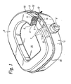
- Figs 1 and 2 illustrate a first embodiment of an earmuff according to the invention.
- the earmuff comprises in a known manner a cup 1 having a headband mounting 2 and a sealing ring 3 arranged around the rim area of the cup.
- the sealing ring 3 comprises an annular covering 5, 6 and, enclosed therein, foam material 4 of an open-cell structure.
- the foam is of a polyester type and typically has a density of about 25 kg/m 3 .
- the annular covering has a stiffer lower or rear part (bottom) 5 in the form of an annular plate and, connected therewith, outwardly directed elastic covering parts 6.
- the sealing ring 3 is arranged on a planar annular flange 7, which is attached to the cup shell 8 and extends inwardly from the circumference of the cup 1 and, thus, defines an opening 19 to the interior of the cup 1.
- the sealing ring 3 can be snapped on in the position shown, the outer annular edge of the annular plate 5 engaging with preferably slightly undercut projections 9 on the circumferential rim 10 of the cup, where the annular flange 7 passes into the rim 10.
- the projections 9 are distributed around the cup 1.
- a large number of holes 11 are uniformly distributed along the outer edge area of the bottom plate.
- Fig. 1 only a few holes 11 are illustrated for the purpose of elucidation.
- the holes 11 are here circular, but they could be designed in an optional manner.
- a number of ventilation ducts 12 are arranged in the portions of the cup 1 connecting with the annular covering 5, 6.
- the ducts 12 are uniformly distributed around the cup, and each duct 12 is, in the embodiment illustrated, adapted to provide air communication with two holes 11 in the bottom plate 5 of the sealing ring.
- the air flow which is thus made possible is illustrated by arrows 13 and 14 in Figs 1 and 2, respectively.
- Each duct 12 is formed of a rectangular recess 15 in the upwardly or forwardly facing surface of the annular flange 7 and the space 16 which is formed between the outer circumferential side portion 17 of the annular covering and the rim area 10 of the cup above the connection of the annular flange 7, between two successive projections 9.
- the ducts 12 open forwardly, laterally and externally of the sealing ring 3, thereby obtaining satisfactory protection against penetration of, for instance, impurities into the ducts 12.
- "forwards” here means inwardly in the direction of the user's head, when the earmuff is arranged over an ear.
- each duct 12 thus is of substantially rectangular cross-section having an essentially constant area.
- the curved configuration of the ducts 12 means that the length of the duct increases. It will be realised that it is possible to affect in a simple manner the length and the area of the duct by varying the duct configuration in the cup wall and/or the annular flange 7, thereby affecting the noise transmission from the environment into the sealing ring.
- a further possibility of easily changing the noise characteristic of an earmuff according to the invention is that the actual sealing ring can readily be exchanged for another sealing ring having a different configuration of the holes in the bottom plate 5.
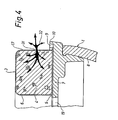
- Fig. 4 illustrates schematically a second embodiment of an earmuff according to the invention. This differs from the earmuff in Figs 1 and 2 merely by ventilation apertures 31 being arranged in the outer circumferential side portion 17 of the annular covering 5, 6. Thus, the bottom plate 5 has no ventilation apertures, and the annular flange 7 has no ventilation ducts.
- the ventilation apertures 31 consist of a large number of through holes in the side portion 17 of the annular covering.
- the holes which suitably are circular, are uniformly distributed along the sealing ring 3.
- the holes are here located on the same level in the side portion of the annular covering, more precisely at about half the height thereof.
- the holes could, however, be positioned on different levels on the ring in a certain pattern for the purpose of ensuring the desired ventilation of the interior of the sealing ring.
- the air flow into and out of the sealing ring 3 is illustrated by means of arrows 32.
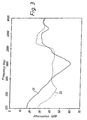
- Fig. 3 illustrates by means of a noise attenuation diagram an example of a change of the noise attenuation characteristic of an earmuff, while using the present invention.
- the diagram which shows "insertion attenuation" measured according to ISO 4869-3, indicates by a full line 21 the noise attenuation curve for an earmuff of the type illustrated in Figs 1 and 2, although without holes 11 and ducts 12. It is evident that the curve is very uneven, with a low low frequency attenuation and a pronounced attenuation peak at about 1000 Hz.
- the diagram also indicates by a dashed line 22 the noise attenuation curve for the earmuff after modification according to the invention.
- the sealing ring has 40 equally large circular holes which are uniformly distributed along the sealing ring, the total area of the holes being about 500 mm 2 .
- the number of ducts 12 is 20 and the duct length is about 5-10 mm, and the duct area is about 25 mm 2 .
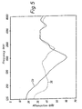
- Fig. 5 illustrates in the same manner as Fig. 3 the change of the noise attenuation characteristic obtained for an earmuff according to Fig. 4 while using the present invention.
- the noise attenuation curve for the earmuff before modification according to the invention is indicated by a full line 33.
- a dashed line 35 indicates the noise attenuation curve after modification, implying that the annular covering 6 of the sealing ring has been provided with 30 equally large and uniformly distributed holes having a total area of about 30 mm 2 .
- the thickness of the annular covering 6 ("acoustic duct length") was about 1 mm.
Landscapes
- Health & Medical Sciences (AREA)
- Life Sciences & Earth Sciences (AREA)
- Engineering & Computer Science (AREA)
- Acoustics & Sound (AREA)
- Physics & Mathematics (AREA)
- Public Health (AREA)
- Biophysics (AREA)
- Otolaryngology (AREA)
- Psychology (AREA)
- Biomedical Technology (AREA)
- Heart & Thoracic Surgery (AREA)
- Vascular Medicine (AREA)
- Animal Behavior & Ethology (AREA)
- General Health & Medical Sciences (AREA)
- Signal Processing (AREA)
- Veterinary Medicine (AREA)
- Soundproofing, Sound Blocking, And Sound Damping (AREA)
- Duct Arrangements (AREA)
- Headphones And Earphones (AREA)
- Pharmaceuticals Containing Other Organic And Inorganic Compounds (AREA)
- Helmets And Other Head Coverings (AREA)
- Adornments (AREA)
- Ventilation (AREA)
- Glass Compositions (AREA)
- Measuring Oxygen Concentration In Cells (AREA)
- Exhaust Silencers (AREA)
- Measuring Pulse, Heart Rate, Blood Pressure Or Blood Flow (AREA)
- Light Receiving Elements (AREA)
- Respiratory Apparatuses And Protective Means (AREA)
Claims (27)
- Verfahren zum Ändern der Schalldämpfung einer Ohrenkappe mit einer Schale (1) mit einem elastischen Dichtungsring (3), der entlang des Öffnungsumfangs der Schale angeordnet ist, wobei der Dichtungsring eine ringförmige Abdeckung (5,6) und darin angeordnet elastisches Material (4) aufweist,
dadurch gekennzeichnet, daß die ringförmige Abdeckung mit Belüftungsöffnungen oder -durchlässen (11) versehen wird, die in Umfangsrichtung entlang des Dichtungsrings (3) verteilt sind und mit der Umgebung in Verbindung stehen, jedoch keine Verbindung mit dem Inneren der Schale haben, wodurch sie die Luftfederwirkung des Dichtungsrings und damit die Schalldämpfungs-charakteristik der Ohrenkappe beeinflussen. - Verfahren nach Anspruch 1,
dadurch gekennzeichnet, daß die Belüftungsöffnungen (11) so verteilt werden und/oder daß die Belüftungsöffnungen (11) eine solche Öffnungsfläche oder verschiedene Öffnungsflächen und/oder eine solche akustische Kanallänge erhalten, daß die Schalldämpfungscharakteristik der Ohrenkappe wahlweise beeinflußt wird. - Verfahren nach Anspruch 1 oder 2,
dadurch gekennzeichnet, daß die ringförmige Abdeckung (5,6) mit Belüftungsöffnungen (11) versehen wird, die wenigstens weitgehend in der Umfangsrichtung gleichmäßig verteilt sind, wodurch die Luft bei niedrigen Frequenzen im wesentlichen ungehemmt aus dem Inneren des Dichtungsrings (3) in die Umgebung strömen kann und umgekehrt, wodurch die Luftfederwirkung des Dichtungsrings wenigstens in einem erheblichen Ausmaß reduziert und die Schalldämpfung bei niedrigen Frequenzen erhöht wird. - Verfahren nach jedem der vorhergehenden Ansprüche,
dadurch gekennzeichnet, daß Belüftungsöffnungen in der Form einer Anzahl von Belüftungslöchern (11) in der ringförmigen Abdeckung (5,6) ausgebildet werden, die entlang des Dichtungsrings (3) verteilt sind, wobei die Belüftungslöcher eine Gesamtfläche von wenigstens etwa 20 mm2, bevorzugt wenigstens etwa 30 mm2, insbesondere mehr als etwa 100 mm2 haben. - Verfahren nach jedem der vorhergehenden Ansprüche,
dadurch gekennzeichnet, daß Belüftungsöffnungen (11) so angeordnet werden, daß die Schalldämpfung innerhalb eines Frequenzbereichs von etwa 125 Hz bis etwa 500 Hz in einem Intervall mit einer Breite von höchstens etwa 20 dB gehalten wird. - Verfahren nach Anspruch 5,
dadurch gekennzeichnet, daß Belüftungsöffnungen (11) so angeordnet werden, daß die Schalldämpfung innerhalb des genannten Frequenzbereichs in einem Intervall mit einer Breite von höchstens etwa 15 dB gehalten wird. - Verfahren nach jedem der Ansprüche 1 bis 4,
dadurch gekennzeichnet, daß Belüftungsöffnungen (11) so angeordnet werden, daß die Schalldämpfung innerhalb eines Frequenzbereichs von etwa 125 Hz bis etwa 1.000 Hz in einem Intervall mit einer Breite von höchstens etwa 20 dB gehalten wird. - Verfahren nach Anspruch 7,
dadurch gekennzeichnet, daß die Belüftungsöffnungen (11) so angeordnet werden, daß die Schalldämpfung innerhalb des genannten Frequenzbereichs in einem Intervall mit einer Breite von höchstens etwa 15 dB gehalten wird. - Verfahren nach jedem der vorhergehenden Ansprüche,
dadurch gekennzeichnet, daß die Belüftungsöffnungen (11) mit der Umgebung durch Belüftungskanäle (12) in Verbindung gebracht werden, die so ausgebildet sind, daß sie eine selektive Schallübertragung in den Dichtungsring (3) hervorrufen, um die Schalldämpfungscharakteristik der Ohrenkappe zu beeinflussen. - Verfahren nach Anspruch 9,
dadurch gekennzeichnet, daß die Belüftungskanäle (12) so ausgebildet werden, daß sie eine erhöhte Schallübertragung in den Dichtungsring (3) hinein in einem oder mehreren Frequenzbereichen hervorrufen, in denen die unbeeinflußte Schall-dämpfung der Ohrenkappe hoch ist, wodurch eine gleichmäßigere Schalldämpfungscharakteristik erhalten wird. - Verfahren nach Anspruch 9 oder 10,
dadurch gekennzeichnet, daß die Belüftungskanäle (12) und die zugehörigen Belüftungsöffnungen so ausgebildet werden, daß eine Schallübertragungsresonanzspitze in einem ausgewählten Frequenzbereich hervorgerufen wird, die sich in Überein-stimmung mit einer Dämpfungsspitze in der Schalldämpfungscharakteristik der unbeeinflußten Ohrenkappe befindet. - Ohrenkappe mit einer Schale (1) mit einem elastischen Dichtungsring (3), der entlang des Öffnungsumfangs der Schale angeordnet ist und eine ringförmige Abdeckung (5,6) und ein darin angeordnetes elastisches Material (4) enthält,
dadurch gekennzeichnet, daß die ringförmige Abdeckung (5,6) mit Belüftungsöffnungen oder -durchlässen (11) in einem äußeren seitlichen Umfangsabschnitt (17) oder einem rückwärtigen Abschnitt (5) versehen ist, wodurch das Innere des Dichtungsrings (3) mit der Umgebung in Verbindung steht, jedoch keine Verbindung mit dem Inneren der Schale (1) hat, wobei die Belüftungsöffnungen (11) in Umfangsrichtung entlang des Dichtungsrings (5) verteilt sind und eine solche Fläche oder solche Flächen haben, daß die Luft aus dem Inneren des Dichtungsrings in die Umgebung strömen kann und umgekehrt, so daß die Luftfederwirkung des Dichtungsrings hierdurch in einem beträchtlichem Ausmaß beeinflußt ist. - Ohrenkappe nach Anspruch 12,
dadurch gekennzeichnet, daß der Dichtungsring (3) Belüftungsöffnungen (11) einer Fläche von wenigstens etwa 1 mm2 pro cm Länge aufweist. - Ohrenkappe nach Anspruch 13,
dadurch gekennzeichnet, daß der Dichtungsring (3) Belüftungsöffnungen (11) einer Fläche von wenigstens etwa 1 mm2, vorzugsweise wenigstens etwa 5 mm2 pro cm Länge aufweist. - Ohrenkappe nach Anspruch 13 oder 14,
dadurch gekennzeichnet, daß der Dichtungsring (3) Belüftungsöffnungen (11) mit einer Gesamtfläche von wenigstens etwa 20 mm2 aufweist. - Ohrenkappe nach Anspruch 15,
dadurch gekennzeichnet, daß der Dichtungsring (3) Belüftungsöffnungen (11) mit einer Gesamtfläche von wenigstens etwa 30 mm2 aufweist. - Ohrenkappe nach Anspruch 15,
dadurch gekennzeichnet, daß der Dichtungsring (3) Belüftungsöffnungen (11) mit einer Gesamtfläche von wenigstens etwa 100 mm2 aufweist. - Ohrenkappe nach jedem der Ansprüche 12 bis 17,
dadurch gekennzeichnet, daß die Belüftungsöffnungen wenigstens weitgehend gleichmäßig entlang des Dichtungsrings (3) verteilt sind und eine solche Öffnungsfläche haben, daß Luft bei niedrigen Frequenzen im wesentlichen ungehemmt aus dem Dichtungsring ausströmen und in diesen einströmen kann, wodurch die Schalldämpfung bei niedrigen Frequenzen erhöht ist. - Ohrenkappe nach jedem der Ansprüche 12 bis 18,
dadurch gekennzeichnet, daß die Belüftungsöffnungen (11) Belüftungslöcher sind, die gleichmäßig in der ringförmigen Abdeckung (5,6) des Dichtungsrings (3) in Umfangsrichtung entlang der ringförmigen Abdeckung verteilt sind, wobei jede Öffnung eine Fläche von wenigstens etwa 1 mm2, bevorzugt von wenigstens etwa 2 mm2 hat. - Ohrenkappe nach jedem der Ansprüche 12 bis 19,
dadurch gekennzeichnet, daß der ringförmige Abdeckungsteil des Dichtungsrings, der der Umgebung zugewandt ist, aus einem luftdurchlässigen Material besteht. - Ohrenkappe nach jedem der Ansprüche 12 bis 19,
dadurch gekennzeichnet, daß die Belüftungsöffnungen (11) in einem unteren oder rückwärtigen ringförmigen Abdeckteil (5) angeordnet sind, durch den der Dichtungsring (3) an der Schale (1) befestigt ist oder an dieser anliegt, wobei Belüftungskanäle (12) in den Schalenabschnitten (7), die mit dem Dichtungsring verbinden, und/oder in dem unteren oder rückwärtigen ringförmigen Abdeckteil ausgebildet sind, durch die die Belüftungsöffnungen (11) mit der Umgebung in Verbindung stehen. - Ohrenkappe nach Anspruch 21,
dadurch gekennzeichnet, daß mehrere Belüftungskanäle (12) um die Öffnung der Schale (1) verteilt zur Belüftung der zugehörigen Dichtungsringteile angeordnet sind. - Ohrenkappe nach Anspruch 21 oder 22,
dadurch gekennzeichnet, daß die Belüftungskanäle (12) in der Schale außerhalb und seitlich des Dichtungsrings (3) geöffnet sind, wobei die Öffnungen der Kanäle nach vorne, von der Schale wegweisen. - Ohrenkappe nach jedem der Ansprüche 21 bis 23,
dadurch gekennzeichnet, daß die Belüftungskanäle (12) so geformt sind, daß sie eine erhöhte Schallübertragung in wenigstens einem ausgewählten Frequenzbereich hervorrufen, in dem die unbeeinflußte Schalldämpfung der Ohrenkappe hoch ist, wodurch die Gesamtdämpfungscharakteristik der Ohrenkappe beeinflußt wird. - Ohrenkappe nach jedem der Ansprüche 21 bis 24,
dadurch gekennzeichnet, daß die Belüftungskanäle (12) einen gekrümmten Verlauf haben. - Ohrenkappe nach jedem der Ansprüche 12 bis 25,
dadurch gekennzeichnet, daß das elastische Material (4) ein Schaummaterial mit einer offen-zelligen Struktur ist. - Ohrenkappe nach Anspruch 26,
dadurch gekennzeichnet, daß das Schaummaterial eine Dichte in dem Bereich von etwa 10 bis 100 kg/m3 hat, bevorzugt von etwa 25 kg/m3.
Applications Claiming Priority (3)
| Application Number | Priority Date | Filing Date | Title |
|---|---|---|---|
| SE9500368 | 1995-02-01 | ||
| SE9500368A SE505203C2 (sv) | 1995-02-01 | 1995-02-01 | Förfarande för att förändra ljuddämpningen hos en öronkåpa samt öronkåpa enligt förfarandet |
| PCT/SE1996/000105 WO1996023462A1 (en) | 1995-02-01 | 1996-01-30 | Earmuff |
Publications (2)
| Publication Number | Publication Date |
|---|---|
| EP0806922A1 EP0806922A1 (de) | 1997-11-19 |
| EP0806922B1 true EP0806922B1 (de) | 2003-09-03 |
Family
ID=20397057
Family Applications (1)
| Application Number | Title | Priority Date | Filing Date |
|---|---|---|---|
| EP96902042A Expired - Lifetime EP0806922B1 (de) | 1995-02-01 | 1996-01-30 | Ohrenkappen |
Country Status (16)
| Country | Link |
|---|---|
| US (1) | US5970160A (de) |
| EP (1) | EP0806922B1 (de) |
| JP (1) | JP3655637B2 (de) |
| KR (1) | KR100294748B1 (de) |
| CN (1) | CN1146370C (de) |
| AT (1) | ATE248565T1 (de) |
| AU (1) | AU689370B2 (de) |
| CA (1) | CA2208531C (de) |
| DE (1) | DE69629798T2 (de) |
| DK (1) | DK0806922T3 (de) |
| ES (1) | ES2206556T3 (de) |
| PL (1) | PL182115B1 (de) |
| PT (1) | PT806922E (de) |
| SE (1) | SE505203C2 (de) |
| TW (1) | TW294880B (de) |
| WO (1) | WO1996023462A1 (de) |
Families Citing this family (40)
| Publication number | Priority date | Publication date | Assignee | Title |
|---|---|---|---|---|
| US6295366B1 (en) * | 1999-03-24 | 2001-09-25 | Flightcom Corporation | Aircraft headset |
| US6597792B1 (en) | 1999-07-15 | 2003-07-22 | Bose Corporation | Headset noise reducing |
| US6684976B1 (en) | 2002-04-12 | 2004-02-03 | David Clark Company Incorporated | Headset ear seal |
| SE528515C2 (sv) * | 2005-04-29 | 2006-12-05 | Peltor Ab | Hörselkåpa med mikrofonanordning |
| US20060269090A1 (en) * | 2005-05-27 | 2006-11-30 | Roman Sapiejewski | Supra-aural headphone noise reducing |
| US20070044206A1 (en) * | 2005-08-29 | 2007-03-01 | Sato Luciana M | Hearing protective earmuff device having frictionally engageable ear cups |
| US7444687B2 (en) * | 2005-08-29 | 2008-11-04 | 3M Innovative Properties Company | Hearing protective device that includes cellular earmuffs |
| US8571227B2 (en) | 2005-11-11 | 2013-10-29 | Phitek Systems Limited | Noise cancellation earphone |
| EP1891917A1 (de) * | 2006-08-24 | 2008-02-27 | Unique Safety Equipment Co., Ltd. | Gepolsteter Überzug für Ohrschutzkappen |
| WO2008070662A2 (en) * | 2006-12-04 | 2008-06-12 | Adaptive Technologies, Inc. | Sound-attenuating earmuff having isolated double-shell structure |
| US8666085B2 (en) * | 2007-10-02 | 2014-03-04 | Phitek Systems Limited | Component for noise reducing earphone |
| US7717226B2 (en) * | 2008-02-20 | 2010-05-18 | Kimberly-Clark Worldwide, Inc. | Hearing protection cap |
| US20090307730A1 (en) * | 2008-05-29 | 2009-12-10 | Mark Donaldson | Media enhancement module |
| US20110002474A1 (en) * | 2009-01-29 | 2011-01-06 | Graeme Colin Fuller | Active Noise Reduction System Control |
| EP2226902A3 (de) * | 2009-03-06 | 2013-03-13 | Phitek Systems Limited | Bordunterhaltungssystemverbinder |
| JP5340833B2 (ja) * | 2009-07-06 | 2013-11-13 | 株式会社オーディオテクニカ | イヤーマフ及びヘッドホン |
| US20110188668A1 (en) * | 2009-09-23 | 2011-08-04 | Mark Donaldson | Media delivery system |
| US9818394B2 (en) | 2009-11-30 | 2017-11-14 | Graeme Colin Fuller | Realisation of controller transfer function for active noise cancellation |
| USD650356S1 (en) * | 2010-01-06 | 2011-12-13 | Skullcandy, Inc. | Eyeglass shaped headphones |
| US20110225705A1 (en) * | 2010-03-16 | 2011-09-22 | 3M Innovative Properties Company | Hearing protective device with moisture resistant earmuff sound absorbers |
| WO2011146429A1 (en) | 2010-05-17 | 2011-11-24 | Thales Avionics, Inc. | Airline passenger seat modular user interface device |
| EP2471710A1 (de) | 2010-11-15 | 2012-07-04 | Nigel Greig | Medienverteilungssystem |
| US9154867B2 (en) | 2011-03-25 | 2015-10-06 | Honeywell Safety Products Usa, Inc. | Earmuff enclosure |
| US9654854B2 (en) | 2011-06-01 | 2017-05-16 | Paul Darlington | In-ear device incorporating active noise reduction |
| WO2013052881A2 (en) | 2011-10-07 | 2013-04-11 | Hearing Components, Inc. | Foam cushion for headphones |
| TWI457009B (zh) * | 2011-12-02 | 2014-10-11 | Giga Byte Tech Co Ltd | 耳機耳殼及耳機 |
| US8651229B2 (en) | 2012-06-05 | 2014-02-18 | Honeywell International Inc. | Hearing protection |
| USD709479S1 (en) * | 2013-01-04 | 2014-07-22 | Barak MELAMED | Headphones earpiece |
| TWD162726S (zh) * | 2013-08-14 | 2014-09-01 | 御穎有限公司 | 耳機飾蓋之部分 |
| USD736174S1 (en) | 2014-02-10 | 2015-08-11 | New Audio LLC | Headphone device |
| CN105516843B (zh) * | 2014-09-24 | 2019-02-15 | 美律电子(深圳)有限公司 | 具有复合包覆套的耳罩 |
| US9438980B2 (en) * | 2014-11-20 | 2016-09-06 | Merry Electronics (Shenzhen) Co., Ltd. | Headphone ear cup |
| AU2015401745B2 (en) * | 2015-07-06 | 2020-10-08 | Wikmanshyttan Safety Ab | A method for manufacturing a sealing ring, and a sealing ring |
| JP6549258B2 (ja) * | 2015-07-07 | 2019-07-24 | シェンゼン ロヨル テクノロジーズ シーオー.,エルティーディー | 耳当て |
| CN105213099A (zh) * | 2015-09-29 | 2016-01-06 | 苏州天裁纺织工艺品有限公司 | 一种双面可拆卸式长度可调耳罩 |
| USD868025S1 (en) * | 2018-03-22 | 2019-11-26 | Neal John Brace | Pair of ear pads |
| WO2019104172A1 (en) * | 2017-11-21 | 2019-05-31 | 3M Innovative Properties Company | A cushion for a hearing protector or audio headset |
| FI128530B (en) | 2017-11-29 | 2020-07-15 | Savox Communications Oy Ab Ltd | Ear cover for hearing protection |
| JP7358895B2 (ja) * | 2019-10-08 | 2023-10-11 | 株式会社Jvcケンウッド | イヤーマフ |
| FI130315B (en) | 2021-05-05 | 2023-06-14 | Fiskars Finland Oy Ab | Ear protection device |
Family Cites Families (6)
| Publication number | Priority date | Publication date | Assignee | Title |
|---|---|---|---|---|
| US2672864A (en) * | 1951-07-18 | 1954-03-23 | Makara Frank | Audio mask |
| FR2579455B3 (fr) * | 1985-03-27 | 1987-08-07 | Lemasson Yves | Dispositif pour proteger l'ouie contre les bruits de haut niveau |
| SE450546B (sv) * | 1985-04-12 | 1987-07-06 | Bilsom Ab | Horselskyddskapa med vermevexlarorgan |
| US4856118A (en) * | 1987-02-11 | 1989-08-15 | Bose Corporation | Headphone cushioning |
| US4993074A (en) * | 1988-04-13 | 1991-02-12 | Carroll Robert J | Earphone spacer |
| US5020163A (en) * | 1989-06-29 | 1991-06-04 | Gentex Corporation | Earseal for sound-attenuating earcup assembly |
-
1995
- 1995-02-01 SE SE9500368A patent/SE505203C2/sv not_active IP Right Cessation
-
1996
- 1996-01-30 WO PCT/SE1996/000105 patent/WO1996023462A1/en not_active Ceased
- 1996-01-30 US US08/860,712 patent/US5970160A/en not_active Expired - Lifetime
- 1996-01-30 CA CA002208531A patent/CA2208531C/en not_active Expired - Lifetime
- 1996-01-30 KR KR1019970705270A patent/KR100294748B1/ko not_active Expired - Fee Related
- 1996-01-30 DE DE69629798T patent/DE69629798T2/de not_active Expired - Lifetime
- 1996-01-30 JP JP52347296A patent/JP3655637B2/ja not_active Expired - Fee Related
- 1996-01-30 AU AU46380/96A patent/AU689370B2/en not_active Expired
- 1996-01-30 AT AT96902042T patent/ATE248565T1/de active
- 1996-01-30 CN CNB961917156A patent/CN1146370C/zh not_active Expired - Lifetime
- 1996-01-30 EP EP96902042A patent/EP0806922B1/de not_active Expired - Lifetime
- 1996-01-30 PT PT96902042T patent/PT806922E/pt unknown
- 1996-01-30 PL PL96321632A patent/PL182115B1/pl not_active IP Right Cessation
- 1996-01-30 ES ES96902042T patent/ES2206556T3/es not_active Expired - Lifetime
- 1996-01-30 DK DK96902042T patent/DK0806922T3/da active
- 1996-01-31 TW TW085101180A patent/TW294880B/zh not_active IP Right Cessation
Also Published As
| Publication number | Publication date |
|---|---|
| PT806922E (pt) | 2003-12-31 |
| JP3655637B2 (ja) | 2005-06-02 |
| EP0806922A1 (de) | 1997-11-19 |
| SE9500368L (sv) | 1996-08-02 |
| ATE248565T1 (de) | 2003-09-15 |
| DE69629798T2 (de) | 2004-07-01 |
| KR100294748B1 (ko) | 2002-06-20 |
| AU689370B2 (en) | 1998-03-26 |
| WO1996023462A1 (en) | 1996-08-08 |
| CA2208531A1 (en) | 1996-08-08 |
| TW294880B (de) | 1997-01-01 |
| US5970160A (en) | 1999-10-19 |
| KR19980701873A (ko) | 1998-06-25 |
| CN1172423A (zh) | 1998-02-04 |
| ES2206556T3 (es) | 2004-05-16 |
| CN1146370C (zh) | 2004-04-21 |
| SE9500368D0 (sv) | 1995-02-01 |
| PL182115B1 (pl) | 2001-11-30 |
| DK0806922T3 (da) | 2003-10-27 |
| DE69629798D1 (de) | 2003-10-09 |
| SE505203C2 (sv) | 1997-07-14 |
| JPH10513068A (ja) | 1998-12-15 |
| AU4638096A (en) | 1996-08-21 |
| CA2208531C (en) | 2006-04-04 |
| PL321632A1 (en) | 1997-12-08 |
Similar Documents
| Publication | Publication Date | Title |
|---|---|---|
| EP0806922B1 (de) | Ohrenkappen | |
| US6683965B1 (en) | In-the-ear noise reduction headphones | |
| EP0688143B1 (de) | Supra-Ohr-Kopfhörer zur aktiven Rauschverminderung | |
| US6219850B1 (en) | Helmet | |
| US10171905B2 (en) | Headphones with frequency-targeted resonance chambers | |
| US8582796B2 (en) | Earmuff and headphone | |
| US6105713A (en) | Cover movable by rotation forming a cerumen barrier in a hearing aid | |
| EP0199689A2 (de) | Ohrabdeckung | |
| KR101644738B1 (ko) | 케이블 스토퍼부재가 구비된 이어폰 | |
| US5815842A (en) | Ear protection cap with improved sound absorption | |
| US12464279B2 (en) | Ear pad or earmold for an earphone, and earphone with an ear pad or earmold | |
| GB2258619A (en) | Ear plug | |
| CN217643647U (zh) | 一种耳塞及耳机 | |
| US11089399B1 (en) | Ear tip with wedge-shaped apertures and earpiece with the same | |
| EP1629806B1 (de) | Gehörschutzstöpsel und Verfahren zu dessen Herstellung | |
| US7542581B2 (en) | Ear insert for a hearing aid | |
| EP3720400B1 (de) | Gehörschutz mit unidirektionalem schalleinlass | |
| CN223540665U (zh) | 一种用于降噪的音乐耳塞 | |
| US20250220337A1 (en) | Open-back headphone | |
| JP2001189997A (ja) | 耳掛け式補聴器 | |
| GB2528119A (en) | Improvements in and relating to loudspeakers |
Legal Events
| Date | Code | Title | Description |
|---|---|---|---|
| PUAI | Public reference made under article 153(3) epc to a published international application that has entered the european phase |
Free format text: ORIGINAL CODE: 0009012 |
|
| 17P | Request for examination filed |
Effective date: 19970725 |
|
| AK | Designated contracting states |
Kind code of ref document: A1 Designated state(s): AT BE CH DE DK ES FR GB GR IE IT LI LU MC NL PT SE |
|
| 17Q | First examination report despatched |
Effective date: 20020125 |
|
| GRAH | Despatch of communication of intention to grant a patent |
Free format text: ORIGINAL CODE: EPIDOS IGRA |
|
| GRAS | Grant fee paid |
Free format text: ORIGINAL CODE: EPIDOSNIGR3 |
|
| RAP1 | Party data changed (applicant data changed or rights of an application transferred) |
Owner name: BACOU-DALLOZ AB |
|
| GRAA | (expected) grant |
Free format text: ORIGINAL CODE: 0009210 |
|
| AK | Designated contracting states |
Kind code of ref document: B1 Designated state(s): AT BE CH DE DK ES FR GB GR IE IT LI LU MC NL PT SE |
|
| REG | Reference to a national code |
Ref country code: GB Ref legal event code: FG4D |
|
| REG | Reference to a national code |
Ref country code: CH Ref legal event code: EP |
|
| REG | Reference to a national code |
Ref country code: CH Ref legal event code: NV Representative=s name: BRAUN & PARTNER PATENT-, MARKEN-, RECHTSANWAELTE |
|
| REF | Corresponds to: |
Ref document number: 69629798 Country of ref document: DE Date of ref document: 20031009 Kind code of ref document: P |
|
| REG | Reference to a national code |
Ref country code: IE Ref legal event code: FG4D |
|
| PG25 | Lapsed in a contracting state [announced via postgrant information from national office to epo] |
Ref country code: GR Free format text: LAPSE BECAUSE OF FAILURE TO SUBMIT A TRANSLATION OF THE DESCRIPTION OR TO PAY THE FEE WITHIN THE PRESCRIBED TIME-LIMIT Effective date: 20031203 |
|
| REG | Reference to a national code |
Ref country code: SE Ref legal event code: TRGR |
|
| PG25 | Lapsed in a contracting state [announced via postgrant information from national office to epo] |
Ref country code: LU Free format text: LAPSE BECAUSE OF NON-PAYMENT OF DUE FEES Effective date: 20040130 Ref country code: IE Free format text: LAPSE BECAUSE OF NON-PAYMENT OF DUE FEES Effective date: 20040130 |
|
| PG25 | Lapsed in a contracting state [announced via postgrant information from national office to epo] |
Ref country code: MC Free format text: LAPSE BECAUSE OF NON-PAYMENT OF DUE FEES Effective date: 20040131 |
|
| ET | Fr: translation filed | ||
| REG | Reference to a national code |
Ref country code: ES Ref legal event code: FG2A Ref document number: 2206556 Country of ref document: ES Kind code of ref document: T3 |
|
| PLBE | No opposition filed within time limit |
Free format text: ORIGINAL CODE: 0009261 |
|
| STAA | Information on the status of an ep patent application or granted ep patent |
Free format text: STATUS: NO OPPOSITION FILED WITHIN TIME LIMIT |
|
| 26N | No opposition filed |
Effective date: 20040604 |
|
| REG | Reference to a national code |
Ref country code: IE Ref legal event code: MM4A |
|
| PGFP | Annual fee paid to national office [announced via postgrant information from national office to epo] |
Ref country code: PT Payment date: 20111229 Year of fee payment: 17 |
|
| PGFP | Annual fee paid to national office [announced via postgrant information from national office to epo] |
Ref country code: CH Payment date: 20120126 Year of fee payment: 17 |
|
| PGFP | Annual fee paid to national office [announced via postgrant information from national office to epo] |
Ref country code: BE Payment date: 20120222 Year of fee payment: 17 Ref country code: IT Payment date: 20120123 Year of fee payment: 17 |
|
| REG | Reference to a national code |
Ref country code: DE Ref legal event code: R082 Ref document number: 69629798 Country of ref document: DE Ref country code: DE Ref legal event code: R082 Ref document number: 69629798 Country of ref document: DE Representative=s name: PATENTANWAELTE QUERMANN, STURM, WEILNAU, DE |
|
| PGFP | Annual fee paid to national office [announced via postgrant information from national office to epo] |
Ref country code: AT Payment date: 20111230 Year of fee payment: 17 |
|
| REG | Reference to a national code |
Ref country code: DE Ref legal event code: R082 Ref document number: 69629798 Country of ref document: DE Representative=s name: PATENTANWAELTE QUERMANN, STURM, WEILNAU, DE |
|
| REG | Reference to a national code |
Ref country code: DE Ref legal event code: R082 Ref document number: 69629798 Country of ref document: DE Representative=s name: PATENTANWAELTE QUERMANN, STURM, WEILNAU, DE |
|
| PGFP | Annual fee paid to national office [announced via postgrant information from national office to epo] |
Ref country code: ES Payment date: 20120124 Year of fee payment: 17 |
|
| BERE | Be: lapsed |
Owner name: *BACOU-DALLOZ A.B. Effective date: 20130131 |
|
| REG | Reference to a national code |
Ref country code: PT Ref legal event code: MM4A Free format text: LAPSE DUE TO NON-PAYMENT OF FEES Effective date: 20130730 |
|
| REG | Reference to a national code |
Ref country code: DE Ref legal event code: R082 Ref document number: 69629798 Country of ref document: DE Representative=s name: QUERMANN STURM WEILNAU PATENTANWAELTE PARTNERS, DE Effective date: 20130625 Ref country code: DE Ref legal event code: R082 Ref document number: 69629798 Country of ref document: DE Representative=s name: QUERMANN STURM WEILNAU PATENTANWAELTE PARTNERS, DE Effective date: 20121030 Ref country code: DE Ref legal event code: R082 Ref document number: 69629798 Country of ref document: DE Representative=s name: QUERMANN STURM WEILNAU PATENTANWAELTE PARTNERS, DE Effective date: 20130422 Ref country code: DE Ref legal event code: R082 Ref document number: 69629798 Country of ref document: DE Representative=s name: PATENTANWAELTE QUERMANN, STURM, WEILNAU, DE Effective date: 20130625 Ref country code: DE Ref legal event code: R082 Ref document number: 69629798 Country of ref document: DE Representative=s name: PATENTANWAELTE QUERMANN, STURM, WEILNAU, DE Effective date: 20121030 Ref country code: DE Ref legal event code: R082 Ref document number: 69629798 Country of ref document: DE Representative=s name: PATENTANWAELTE QUERMANN, STURM, WEILNAU, DE Effective date: 20130422 Ref country code: DE Ref legal event code: R081 Ref document number: 69629798 Country of ref document: DE Owner name: HONEYWELL SAFETY PRODUCTS SWEDEN AB, SE Free format text: FORMER OWNER: BACOU-DALLOZ AB, BILLESHOLM, SE Effective date: 20130625 |
|
| REG | Reference to a national code |
Ref country code: FR Ref legal event code: CD Owner name: HONEYWELL SAFETY PRODUCTS SWEDEN AB, SE Effective date: 20130719 Ref country code: FR Ref legal event code: CA Effective date: 20130719 |
|
| REG | Reference to a national code |
Ref country code: CH Ref legal event code: PL |
|
| REG | Reference to a national code |
Ref country code: AT Ref legal event code: MM01 Ref document number: 248565 Country of ref document: AT Kind code of ref document: T Effective date: 20130131 |
|
| REG | Reference to a national code |
Ref country code: NL Ref legal event code: TD Effective date: 20131009 |
|
| PG25 | Lapsed in a contracting state [announced via postgrant information from national office to epo] |
Ref country code: LI Free format text: LAPSE BECAUSE OF NON-PAYMENT OF DUE FEES Effective date: 20130131 Ref country code: AT Free format text: LAPSE BECAUSE OF NON-PAYMENT OF DUE FEES Effective date: 20130131 Ref country code: PT Free format text: LAPSE BECAUSE OF NON-PAYMENT OF DUE FEES Effective date: 20130730 Ref country code: CH Free format text: LAPSE BECAUSE OF NON-PAYMENT OF DUE FEES Effective date: 20130131 Ref country code: BE Free format text: LAPSE BECAUSE OF NON-PAYMENT OF DUE FEES Effective date: 20130131 |
|
| REG | Reference to a national code |
Ref country code: GB Ref legal event code: 732E Free format text: REGISTERED BETWEEN 20131017 AND 20131023 |
|
| PG25 | Lapsed in a contracting state [announced via postgrant information from national office to epo] |
Ref country code: IT Free format text: LAPSE BECAUSE OF NON-PAYMENT OF DUE FEES Effective date: 20130130 |
|
| REG | Reference to a national code |
Ref country code: ES Ref legal event code: FD2A Effective date: 20140321 |
|
| PG25 | Lapsed in a contracting state [announced via postgrant information from national office to epo] |
Ref country code: ES Free format text: LAPSE BECAUSE OF NON-PAYMENT OF DUE FEES Effective date: 20130131 |
|
| PGFP | Annual fee paid to national office [announced via postgrant information from national office to epo] |
Ref country code: DK Payment date: 20141230 Year of fee payment: 20 Ref country code: GB Payment date: 20141230 Year of fee payment: 20 |
|
| PGFP | Annual fee paid to national office [announced via postgrant information from national office to epo] |
Ref country code: FR Payment date: 20141226 Year of fee payment: 20 |
|
| PGFP | Annual fee paid to national office [announced via postgrant information from national office to epo] |
Ref country code: NL Payment date: 20150115 Year of fee payment: 20 |
|
| PGFP | Annual fee paid to national office [announced via postgrant information from national office to epo] |
Ref country code: DE Payment date: 20150126 Year of fee payment: 20 |
|
| PGFP | Annual fee paid to national office [announced via postgrant information from national office to epo] |
Ref country code: SE Payment date: 20150108 Year of fee payment: 20 |
|
| REG | Reference to a national code |
Ref country code: DE Ref legal event code: R071 Ref document number: 69629798 Country of ref document: DE |
|
| REG | Reference to a national code |
Ref country code: DK Ref legal event code: EUP Effective date: 20160130 |
|
| REG | Reference to a national code |
Ref country code: NL Ref legal event code: MK Effective date: 20160129 |
|
| REG | Reference to a national code |
Ref country code: GB Ref legal event code: PE20 Expiry date: 20160129 |
|
| REG | Reference to a national code |
Ref country code: SE Ref legal event code: EUG |
|
| PG25 | Lapsed in a contracting state [announced via postgrant information from national office to epo] |
Ref country code: GB Free format text: LAPSE BECAUSE OF EXPIRATION OF PROTECTION Effective date: 20160129 |