EP0806922B1 - Earmuff - Google Patents
Earmuff Download PDFInfo
- Publication number
- EP0806922B1 EP0806922B1 EP96902042A EP96902042A EP0806922B1 EP 0806922 B1 EP0806922 B1 EP 0806922B1 EP 96902042 A EP96902042 A EP 96902042A EP 96902042 A EP96902042 A EP 96902042A EP 0806922 B1 EP0806922 B1 EP 0806922B1
- Authority
- EP
- European Patent Office
- Prior art keywords
- sealing ring
- earmuff
- ventilation
- ventilation apertures
- noise attenuation
- Prior art date
- Legal status (The legal status is an assumption and is not a legal conclusion. Google has not performed a legal analysis and makes no representation as to the accuracy of the status listed.)
- Expired - Lifetime
Links
Images

Classifications
-
- H—ELECTRICITY
- H04—ELECTRIC COMMUNICATION TECHNIQUE
- H04R—LOUDSPEAKERS, MICROPHONES, GRAMOPHONE PICK-UPS OR LIKE ACOUSTIC ELECTROMECHANICAL TRANSDUCERS; DEAF-AID SETS; PUBLIC ADDRESS SYSTEMS
- H04R1/00—Details of transducers, loudspeakers or microphones
- H04R1/10—Earpieces; Attachments therefor ; Earphones; Monophonic headphones
- H04R1/1083—Reduction of ambient noise
-
- A—HUMAN NECESSITIES
- A61—MEDICAL OR VETERINARY SCIENCE; HYGIENE
- A61F—FILTERS IMPLANTABLE INTO BLOOD VESSELS; PROSTHESES; DEVICES PROVIDING PATENCY TO, OR PREVENTING COLLAPSING OF, TUBULAR STRUCTURES OF THE BODY, e.g. STENTS; ORTHOPAEDIC, NURSING OR CONTRACEPTIVE DEVICES; FOMENTATION; TREATMENT OR PROTECTION OF EYES OR EARS; BANDAGES, DRESSINGS OR ABSORBENT PADS; FIRST-AID KITS
- A61F11/00—Methods or devices for treatment of the ears or hearing sense; Non-electric hearing aids; Methods or devices for enabling ear patients to achieve auditory perception through physiological senses other than hearing sense; Protective devices for the ears, carried on the body or in the hand
- A61F11/06—Protective devices for the ears
- A61F11/14—Protective devices for the ears external, e.g. earcaps or earmuffs
-
- H—ELECTRICITY
- H04—ELECTRIC COMMUNICATION TECHNIQUE
- H04R—LOUDSPEAKERS, MICROPHONES, GRAMOPHONE PICK-UPS OR LIKE ACOUSTIC ELECTROMECHANICAL TRANSDUCERS; DEAF-AID SETS; PUBLIC ADDRESS SYSTEMS
- H04R1/00—Details of transducers, loudspeakers or microphones
- H04R1/10—Earpieces; Attachments therefor ; Earphones; Monophonic headphones
Definitions
- the present invention relates generally to an earmuff of the type having a cup with an elastic sealing ring arranged along the opening circumference of the cup, said sealing ring comprising an annular covering and, arranged therein, elastic material, preferably foam material. More specifically, the invention relates to a method for changing the noise attenuation characteristic of such an earmuff, as well as an earmuff obtained in accordance therewith.
- the sealing ring of the earmuff can seal efficiently against the user's head.
- the covering of the sealing ring is, as a rule, provided with a small hole or some small holes, which permit pressure compensation as the sealing ring, while being compressed to some extent, is applied to the user's head around an ear. After that, no substantial penetration of noise into the sealing ring takes place.
- An earmuff according to the preamble of claim 12 is known from SE-B-450 546.
- the main object of the present invention is to indicate how to change the noise attenuation characteristic of an earmuff while using the sealing ring, especially how to increase its low frequency attenuation and/or to make its noise attenuation characteristic more even.
- a further object of the present invention is to indicate how such a change can occur selectively.
- the invention is thus based on the knowledge that the noise attenuation characteristic of the earmuff can be affected by manipulation of the effect of the inner air spring of the sealing ring. Such affecting can be achieved by providing the annular covering with ventilation apertures or passages, by means of which the interior of the sealing ring, after application of the earmuff, communicates with the environment without communicating with the interior of the cup. It is a matter of ventilation apertures of a substantially larger total area than the prior-art pressure compensation holes in the sealing ring covering, which are mentioned by way of introduction.
- the annular covering of the sealing ring is provided with ventilation apertures which are preferably uniformly distributed in the circumferential direction and which can suitably be ventilation holes, although it would be possible to have a different structure of the annular covering in order to provide the desired ventilation apertures.
- Ventilation apertures or holes each having an area of at least about 1 mm 2 , preferably at least about 2 mm 2 .
- a total aperture or hole area of at least about 20 mm 2 is preferred, more preferably at least about 30 mm 2 .
- an area of more than 100 mm 2 can be used, with excellent results.
- the ventilation apertures or holes should suitably have an area of at least about 1 mm 2 per centimetre of length, preferably at least about 5 mm 2 per centimetre of length.
- Ventilation apertures communicate with the environment through special ventilation ducts, which can advantageously be arranged in the cup and/or annular covering parts. These ducts yield a possibility of protection against penetration of dirt etc. into the sealing ring from the environment, as well as an additional possibility of selectively affecting the noise attenuation characteristic, as will be described in more detail below.
- the ventilation apertures are arranged in the annular covering of the sealing ring preferably in a lower or rear annular covering part, by means of which the sealing ring is attached to or abuts against the cup, ventilation ducts advantageously being arranged in the sealing ring connecting parts of the cup and/or in said lower or rear annular covering part, which can, in a manner known per se, be made stronger and stiffer than the remaining annular covering.
- the ventilation apertures and their communication with the environment are arranged such that, above all at low frequencies, the air can flow substantially unimpededly out of the interior of the sealing ring to the environment and vice versa, the air spring action of the sealing ring being reduced at least to a substantial extent, which results in a pronounced increase of the low frequency noise attenuation, while obtaining a certain reduction of the noise attenuation at higher frequencies.
- Ventilation apertures such that the attenuation in a frequency range from about 125 Hz to at least about 500 Hz, most advantageously at least to about 1000 Hz, is kept in an interval having a width of about 20 dB at most, especially about 15 dB at most.
- ventilation apertures and their communication with the environment are arranged such that a selective noise transmission is possible into the sealing ring for the purpose of affecting the noise attenuation characteristic of the earmuff.
- use can advantageously be made of special ventilation ducts of the above-mentioned type.
- ventilation ducts can be designed such that they affect the noise attenuation to a small extent, it is also easy to dimension all or selected ventilation ducts so as to produce a selectively increased noise transmission into the sealing ring in one or more frequency ranges, which results in the noise attenuation characteristic being affected.
- Frequency ranges which are of interest for such selective noise transmission are above all those in which the unaffected noise attenuation of the earmuff is high, thereby obtaining a more even noise attenuation characteristic.
- the latter aspect of the invention can be regarded as a possibility of providing selective "acoustic ducts" into the sealing ring from the environment.
- the noise transmission through each acoustic duct and, thus, the effect on the noise attenuation characteristic will be connected to the resonance frequency that applies to the duct at issue, said resonance frequency being determined by a spring-mass system, the spring being determined by an associated air spring inside the sealing ring and the mass being determined by the dimensions of the duct, above all its length and its area.
- a narrow and high resonance peak results in a narrower influence on the noise attenuation characteristic, while a wide and low resonance peak results in a wider influence on the noise attenuation characteristic.
- the appearance of the resonance peak can be affected by introducing a suitable acoustic resistance into the duct.
- an "acoustic duct" comprises one or more ventilation apertures in combination with a ventilation duct of the above-mentioned type
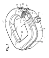
- Figs 1 and 2 illustrate a first embodiment of an earmuff according to the invention.
- the earmuff comprises in a known manner a cup 1 having a headband mounting 2 and a sealing ring 3 arranged around the rim area of the cup.
- the sealing ring 3 comprises an annular covering 5, 6 and, enclosed therein, foam material 4 of an open-cell structure.
- the foam is of a polyester type and typically has a density of about 25 kg/m 3 .
- the annular covering has a stiffer lower or rear part (bottom) 5 in the form of an annular plate and, connected therewith, outwardly directed elastic covering parts 6.
- the sealing ring 3 is arranged on a planar annular flange 7, which is attached to the cup shell 8 and extends inwardly from the circumference of the cup 1 and, thus, defines an opening 19 to the interior of the cup 1.
- the sealing ring 3 can be snapped on in the position shown, the outer annular edge of the annular plate 5 engaging with preferably slightly undercut projections 9 on the circumferential rim 10 of the cup, where the annular flange 7 passes into the rim 10.
- the projections 9 are distributed around the cup 1.
- a large number of holes 11 are uniformly distributed along the outer edge area of the bottom plate.
- Fig. 1 only a few holes 11 are illustrated for the purpose of elucidation.
- the holes 11 are here circular, but they could be designed in an optional manner.
- a number of ventilation ducts 12 are arranged in the portions of the cup 1 connecting with the annular covering 5, 6.
- the ducts 12 are uniformly distributed around the cup, and each duct 12 is, in the embodiment illustrated, adapted to provide air communication with two holes 11 in the bottom plate 5 of the sealing ring.
- the air flow which is thus made possible is illustrated by arrows 13 and 14 in Figs 1 and 2, respectively.
- Each duct 12 is formed of a rectangular recess 15 in the upwardly or forwardly facing surface of the annular flange 7 and the space 16 which is formed between the outer circumferential side portion 17 of the annular covering and the rim area 10 of the cup above the connection of the annular flange 7, between two successive projections 9.
- the ducts 12 open forwardly, laterally and externally of the sealing ring 3, thereby obtaining satisfactory protection against penetration of, for instance, impurities into the ducts 12.
- "forwards” here means inwardly in the direction of the user's head, when the earmuff is arranged over an ear.
- each duct 12 thus is of substantially rectangular cross-section having an essentially constant area.
- the curved configuration of the ducts 12 means that the length of the duct increases. It will be realised that it is possible to affect in a simple manner the length and the area of the duct by varying the duct configuration in the cup wall and/or the annular flange 7, thereby affecting the noise transmission from the environment into the sealing ring.
- a further possibility of easily changing the noise characteristic of an earmuff according to the invention is that the actual sealing ring can readily be exchanged for another sealing ring having a different configuration of the holes in the bottom plate 5.
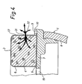
- Fig. 4 illustrates schematically a second embodiment of an earmuff according to the invention. This differs from the earmuff in Figs 1 and 2 merely by ventilation apertures 31 being arranged in the outer circumferential side portion 17 of the annular covering 5, 6. Thus, the bottom plate 5 has no ventilation apertures, and the annular flange 7 has no ventilation ducts.
- the ventilation apertures 31 consist of a large number of through holes in the side portion 17 of the annular covering.
- the holes which suitably are circular, are uniformly distributed along the sealing ring 3.
- the holes are here located on the same level in the side portion of the annular covering, more precisely at about half the height thereof.
- the holes could, however, be positioned on different levels on the ring in a certain pattern for the purpose of ensuring the desired ventilation of the interior of the sealing ring.
- the air flow into and out of the sealing ring 3 is illustrated by means of arrows 32.
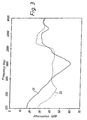
- Fig. 3 illustrates by means of a noise attenuation diagram an example of a change of the noise attenuation characteristic of an earmuff, while using the present invention.
- the diagram which shows "insertion attenuation" measured according to ISO 4869-3, indicates by a full line 21 the noise attenuation curve for an earmuff of the type illustrated in Figs 1 and 2, although without holes 11 and ducts 12. It is evident that the curve is very uneven, with a low low frequency attenuation and a pronounced attenuation peak at about 1000 Hz.
- the diagram also indicates by a dashed line 22 the noise attenuation curve for the earmuff after modification according to the invention.
- the sealing ring has 40 equally large circular holes which are uniformly distributed along the sealing ring, the total area of the holes being about 500 mm 2 .
- the number of ducts 12 is 20 and the duct length is about 5-10 mm, and the duct area is about 25 mm 2 .
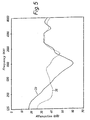
- Fig. 5 illustrates in the same manner as Fig. 3 the change of the noise attenuation characteristic obtained for an earmuff according to Fig. 4 while using the present invention.
- the noise attenuation curve for the earmuff before modification according to the invention is indicated by a full line 33.
- a dashed line 35 indicates the noise attenuation curve after modification, implying that the annular covering 6 of the sealing ring has been provided with 30 equally large and uniformly distributed holes having a total area of about 30 mm 2 .
- the thickness of the annular covering 6 ("acoustic duct length") was about 1 mm.
Abstract
Description
Claims (27)
- A method for changing the noise attenuation of an earmuff having a cup (1) with an elastic sealing ring (3) arranged along the opening circumference of the cup, said sealing ring comprising an annular covering (5,6) and, arranged therein, elastic material (4), characterised by providing the annular covering with ventilation apertures or passages (11) which are distributed circumferentially along the sealing ring (3) and which communicate with the environment, but have no communication with the interior of the cup, thereby affecting the air spring action of the sealing ring and, thus, the noise attenuation characteristic of the earmuff.
- The method as claimed in claim 1, characterised by distributing the ventilation apertures (11) and/or giving the ventilation apertures (11) such an opening area or different opening areas and/or such an acoustic duct length that the noise attenuation characteristic of the earmuff is affected selectively.
- The method as claimed in claim 1 or 2, characterised by providing the annular covering (5,6) with ventilation apertures (11) distributed at least substantially uniformly in the circumferential direction, whereby the air, at low frequencies, can flow substantially unimpededly out of the interior of the sealing ring (3) to the environment and vice versa, thereby reducing the air spring action of the sealing ring at least to a substantial extent and increasing the noise attenuation at low frequencies.
- The method as claimed in any one of the preceding claims, characterised by arranging ventilation apertures in the form of a number of ventilation holes (11) in the annular covering (5,6), which are distributed along the sealing ring (3), the ventilation holes having a total area of at least about 20 mm2, preferably at least about 30 mm2, especially more than about 100 mm2.
- The method as claimed in any one of the preceding claims, characterised by arranging ventilation apertures (11) such that the noise attenuation within a frequency range from about 125 Hz to about 500 Hz is kept in an interval having a width of about 20 dB at most.
- The method as claimed in claim 5, characterised by arranging ventilation apertures such that the noise attenuation within said frequency range is kept in an interval having a width of about 15 dB at most.
- The method as claimed in any one of claims 1-4,
characterised by arranging ventilation apertures (11) such that the noise attenuation within a frequency range from about 125 Hz to about 1000 Hz is kept in an interval having a width of about 20 dB at most. - The method as claimed in claim 7, characterised by arranging ventilation apertures such that the noise attenuation within said frequency range is kept in an interval having a width of about 15 dB at most.
- The method as claimed in any one of the preceding claims, characterised by causing ventilation apertures (11) to communicate with the environment through ventilation ducts (12), which are designed to produce a selective noise transmission into the sealing ring (3) for the purpose of affecting the noise attenuation characteristic of the earmuff.
- The method as claimed in claim 9, characterised by designing ventilation ducts (12) so as to produce an increased noise transmission into the sealing ring (3) in one or more frequency ranges, in which the unaffected noise attenuation of the earmuff is high, thereby obtaining a more even noise attenuation characteristic.
- The method as claimed in claim 9 or 10, characterised by designing ventilation ducts (12) and corresponding ventilation apertures (11) so as to produce a noise transmission resonance peak in a selected frequency range conforming to an attenuation peak in the noise attenuation characteristic of the unaffected earmuff.
- An earmuff having a cup (1) with an elastic sealing ring (3) arranged along the opening circumference of the cup, said sealing ring comprising an annular covering (5,6) and, arranged therein, elastic material (4), characterised in that the annular covering (5,6) is provided with ventilation apertures or passages (11) in an outer circumferential side portion (17) or rear portion (5) thereof, whereby the interior of the sealing ring (3) communicates with the environment, but has no communication with the interior of the cup (1), the ventilation apertures (11) being distributed circumferentially along the sealing ring (3) and having such an area or such areas that air can flow out of the interior of the sealing ring to the environment and vice versa, such that the air spring action of the sealing ring is affected thereby to a substantial extent.
- The earmuff as claimed in claim 12, characterised in that the sealing ring (3) has ventilation aperture (11) of an area of at least about 1 mm2 per centimetre of length.
- The earmuff as claimed in claim 13, characterised in that the sealing ring (3) has ventilation apertures (11) of an area of at least about 1 mm2, preferably at least about 5 mm2 per centimetre of length.
- The earmuff as claimed in claim 13 or 14, characterised in that the sealing ring (3) has ventilation apertures (11) having a total area of at least about 20 mm2.
- The earmuff as claimed in claim 15, characterised in that the sealing ring (3) has ventilation apertures (11) having a total area of at least about 30 mm2.
- The earmuff as claimed in claim 15, characterised in that the sealing ring (3) has ventilation apertures (11) having a total area of at least about 100 mm2.
- The earmuff as claimed in any one of claims 12-17, characterised in that the ventilation apertures (11) are at least substantially uniformly distributed along the sealing ring (3) and have such an opening area that air, at low frequencies, can flow substantially unimpededly out of and into the sealing ring, thereby increasing the noise attenuation at low frequencies.
- The earmuff as claimed in any one of claims 12-18, characterised in that the ventilation apertures (11) are ventilation holes uniformly distributed in the annular covering (5,6) of the sealing ring (3), circumferentially along said annular covering, each aperture having an area of at least about 1 mm2, at least about 2 mm2.
- The earmuff as claimed in any one of claims 12-19, characterised in that the annular covering part of the sealing ring facing the environment is made of an air-permeable material.
- The earmuff as claimed in any one of claims 12-19, characterised in that the ventilation apertures (11) are arranged in a lower or rear annular covering part (5), by means of which the sealing ring (3) is attached to or abuts against the cup (1), ventilation ducts (12) being arranged in the cup portions (7) connecting with the sealing ring and/or in said lower or rear annular covering part, through which ventilation ducts (12) the ventilation apertures (11) communicate with the environment.
- The earmuff as claimed in claim 21, characterised in that a number of ventilation ducts (12) are distributed around the opening of the cup (1) for ventilation of corresponding sealing ring members.
- The earmuff as claimed in claim 21 or 22, characterised in that the ventilation ducts (12) open externally and laterally of the sealing ring (3) in the cup, the duct openings facing forwards, away from the cup.
- The earmuff as claimed in any one of claims 21-23, characterised in that ventilation ducts (12) are formed to produce an increased noise transmission in at least one selected frequency range, in which the unaffected noise attenuation of the earmuff is high, thereby affecting the total attenuation characteristic of the earmuff.
- The earmuff as claimed in any one of claims 21-24, characterised in that the ventilation ducts (12) extend in a curved manner.
- The earmuff as claimed in any one of claims 12-25, characterised in that the elastic material (4) is a foam material having an open-cell structure.
- The earmuff as claimed in claim 26 characterised in that the foam material has a density in the range from about 10 to about 100 kg/m3, preferably about 25 Kg/m3.
Applications Claiming Priority (3)
| Application Number | Priority Date | Filing Date | Title |
|---|---|---|---|
| SE9500368A SE505203C2 (en) | 1995-02-01 | 1995-02-01 | A method for changing the sound attenuation of an earmuff as well as the earmuff according to the method |
| SE9500368 | 1995-02-01 | ||
| PCT/SE1996/000105 WO1996023462A1 (en) | 1995-02-01 | 1996-01-30 | Earmuff |
Publications (2)
| Publication Number | Publication Date |
|---|---|
| EP0806922A1 EP0806922A1 (en) | 1997-11-19 |
| EP0806922B1 true EP0806922B1 (en) | 2003-09-03 |
Family
ID=20397057
Family Applications (1)
| Application Number | Title | Priority Date | Filing Date |
|---|---|---|---|
| EP96902042A Expired - Lifetime EP0806922B1 (en) | 1995-02-01 | 1996-01-30 | Earmuff |
Country Status (16)
| Country | Link |
|---|---|
| US (1) | US5970160A (en) |
| EP (1) | EP0806922B1 (en) |
| JP (1) | JP3655637B2 (en) |
| KR (1) | KR100294748B1 (en) |
| CN (1) | CN1146370C (en) |
| AT (1) | ATE248565T1 (en) |
| AU (1) | AU689370B2 (en) |
| CA (1) | CA2208531C (en) |
| DE (1) | DE69629798T2 (en) |
| DK (1) | DK0806922T3 (en) |
| ES (1) | ES2206556T3 (en) |
| PL (1) | PL182115B1 (en) |
| PT (1) | PT806922E (en) |
| SE (1) | SE505203C2 (en) |
| TW (1) | TW294880B (en) |
| WO (1) | WO1996023462A1 (en) |
Families Citing this family (35)
| Publication number | Priority date | Publication date | Assignee | Title |
|---|---|---|---|---|
| US6295366B1 (en) * | 1999-03-24 | 2001-09-25 | Flightcom Corporation | Aircraft headset |
| US6597792B1 (en) | 1999-07-15 | 2003-07-22 | Bose Corporation | Headset noise reducing |
| US6684976B1 (en) | 2002-04-12 | 2004-02-03 | David Clark Company Incorporated | Headset ear seal |
| SE528515C2 (en) * | 2005-04-29 | 2006-12-05 | Peltor Ab | Earphone with microphone device |
| US20060269090A1 (en) * | 2005-05-27 | 2006-11-30 | Roman Sapiejewski | Supra-aural headphone noise reducing |
| US20070044206A1 (en) * | 2005-08-29 | 2007-03-01 | Sato Luciana M | Hearing protective earmuff device having frictionally engageable ear cups |
| US7444687B2 (en) * | 2005-08-29 | 2008-11-04 | 3M Innovative Properties Company | Hearing protective device that includes cellular earmuffs |
| US8571227B2 (en) | 2005-11-11 | 2013-10-29 | Phitek Systems Limited | Noise cancellation earphone |
| EP1891917A1 (en) * | 2006-08-24 | 2008-02-27 | Unique Safety Equipment Co., Ltd. | Cushion cover for earmuffs |
| US7703572B2 (en) * | 2006-12-04 | 2010-04-27 | Adaptive Technologies, Inc. | Sound-attenuating earmuff having isolated double-shell structure |
| US8666085B2 (en) * | 2007-10-02 | 2014-03-04 | Phitek Systems Limited | Component for noise reducing earphone |
| US7717226B2 (en) * | 2008-02-20 | 2010-05-18 | Kimberly-Clark Worldwide, Inc. | Hearing protection cap |
| EP2129114A3 (en) * | 2008-05-29 | 2011-11-02 | Phitek Systems Limited | Media enhancement module |
| US20110002474A1 (en) * | 2009-01-29 | 2011-01-06 | Graeme Colin Fuller | Active Noise Reduction System Control |
| US20110003505A1 (en) * | 2009-03-06 | 2011-01-06 | Nigel Greig | In-flight entertainment system connector |
| JP5340833B2 (en) * | 2009-07-06 | 2013-11-13 | 株式会社オーディオテクニカ | Ear muffs and headphones |
| US20110188668A1 (en) * | 2009-09-23 | 2011-08-04 | Mark Donaldson | Media delivery system |
| US9818394B2 (en) * | 2009-11-30 | 2017-11-14 | Graeme Colin Fuller | Realisation of controller transfer function for active noise cancellation |
| US20110225705A1 (en) * | 2010-03-16 | 2011-09-22 | 3M Innovative Properties Company | Hearing protective device with moisture resistant earmuff sound absorbers |
| BR112012028245B1 (en) | 2010-05-17 | 2021-04-20 | Phitek Systems, Ltd. | module support unit and video display unit |
| US9487295B2 (en) | 2010-11-15 | 2016-11-08 | William James Sim | Vehicle media distribution system using optical transmitters |
| US9154867B2 (en) | 2011-03-25 | 2015-10-06 | Honeywell Safety Products Usa, Inc. | Earmuff enclosure |
| CN103748903B (en) | 2011-06-01 | 2017-02-22 | 菲泰克系统有限公司 | In-ear device incorporating active noise reduction |
| WO2013052881A2 (en) | 2011-10-07 | 2013-04-11 | Hearing Components, Inc. | Foam cushion for headphones |
| TWI457009B (en) * | 2011-12-02 | 2014-10-11 | Giga Byte Tech Co Ltd | Earmuff and earphone |
| US8651229B2 (en) | 2012-06-05 | 2014-02-18 | Honeywell International Inc. | Hearing protection |
| USD736174S1 (en) | 2014-02-10 | 2015-08-11 | New Audio LLC | Headphone device |
| CN105516843B (en) * | 2014-09-24 | 2019-02-15 | 美律电子(深圳)有限公司 | Earmuff with compound coating set |
| US9438980B2 (en) * | 2014-11-20 | 2016-09-06 | Merry Electronics (Shenzhen) Co., Ltd. | Headphone ear cup |
| CA2991477C (en) * | 2015-07-06 | 2022-11-01 | Wikmanshyttan Safety Ab | A method for manufacturing a sealing ring, and a sealing ring. |
| WO2017004784A1 (en) * | 2015-07-07 | 2017-01-12 | 深圳市柔宇科技有限公司 | Ear muff |
| CN105213099A (en) * | 2015-09-29 | 2016-01-06 | 苏州天裁纺织工艺品有限公司 | A kind of dismountable on both sides adjustable length earmuff |
| USD868025S1 (en) * | 2018-03-22 | 2019-11-26 | Neal John Brace | Pair of ear pads |
| EP3713531A4 (en) * | 2017-11-21 | 2021-10-06 | 3M Innovative Properties Company | A cushion for a hearing protector or audio headset |
| FI128530B (en) * | 2017-11-29 | 2020-07-15 | Savox Communications Oy Ab Ltd | An ear cup assembly for a hearing protector |
Family Cites Families (6)
| Publication number | Priority date | Publication date | Assignee | Title |
|---|---|---|---|---|
| US2672864A (en) * | 1951-07-18 | 1954-03-23 | Makara Frank | Audio mask |
| FR2579455B3 (en) * | 1985-03-27 | 1987-08-07 | Lemasson Yves | DEVICE FOR PROTECTING THE HEAR FROM HIGH-LEVEL NOISE |
| SE450546B (en) * | 1985-04-12 | 1987-07-06 | Bilsom Ab | Ear protector |
| US4856118A (en) * | 1987-02-11 | 1989-08-15 | Bose Corporation | Headphone cushioning |
| US4993074A (en) * | 1988-04-13 | 1991-02-12 | Carroll Robert J | Earphone spacer |
| US5020163A (en) * | 1989-06-29 | 1991-06-04 | Gentex Corporation | Earseal for sound-attenuating earcup assembly |
-
1995
- 1995-02-01 SE SE9500368A patent/SE505203C2/en not_active IP Right Cessation
-
1996
- 1996-01-30 ES ES96902042T patent/ES2206556T3/en not_active Expired - Lifetime
- 1996-01-30 JP JP52347296A patent/JP3655637B2/en not_active Expired - Fee Related
- 1996-01-30 AT AT96902042T patent/ATE248565T1/en active
- 1996-01-30 DK DK96902042T patent/DK0806922T3/en active
- 1996-01-30 PL PL96321632A patent/PL182115B1/en not_active IP Right Cessation
- 1996-01-30 US US08/860,712 patent/US5970160A/en not_active Expired - Lifetime
- 1996-01-30 CA CA002208531A patent/CA2208531C/en not_active Expired - Lifetime
- 1996-01-30 KR KR1019970705270A patent/KR100294748B1/en not_active IP Right Cessation
- 1996-01-30 AU AU46380/96A patent/AU689370B2/en not_active Expired
- 1996-01-30 WO PCT/SE1996/000105 patent/WO1996023462A1/en active IP Right Grant
- 1996-01-30 PT PT96902042T patent/PT806922E/en unknown
- 1996-01-30 EP EP96902042A patent/EP0806922B1/en not_active Expired - Lifetime
- 1996-01-30 CN CNB961917156A patent/CN1146370C/en not_active Expired - Lifetime
- 1996-01-30 DE DE69629798T patent/DE69629798T2/en not_active Expired - Lifetime
- 1996-01-31 TW TW085101180A patent/TW294880B/zh not_active IP Right Cessation
Also Published As
| Publication number | Publication date |
|---|---|
| PL321632A1 (en) | 1997-12-08 |
| CA2208531A1 (en) | 1996-08-08 |
| KR100294748B1 (en) | 2002-06-20 |
| CA2208531C (en) | 2006-04-04 |
| TW294880B (en) | 1997-01-01 |
| DK0806922T3 (en) | 2003-10-27 |
| CN1172423A (en) | 1998-02-04 |
| JP3655637B2 (en) | 2005-06-02 |
| CN1146370C (en) | 2004-04-21 |
| KR19980701873A (en) | 1998-06-25 |
| DE69629798D1 (en) | 2003-10-09 |
| SE505203C2 (en) | 1997-07-14 |
| JPH10513068A (en) | 1998-12-15 |
| SE9500368L (en) | 1996-08-02 |
| PT806922E (en) | 2003-12-31 |
| DE69629798T2 (en) | 2004-07-01 |
| US5970160A (en) | 1999-10-19 |
| PL182115B1 (en) | 2001-11-30 |
| AU689370B2 (en) | 1998-03-26 |
| EP0806922A1 (en) | 1997-11-19 |
| AU4638096A (en) | 1996-08-21 |
| ES2206556T3 (en) | 2004-05-16 |
| ATE248565T1 (en) | 2003-09-15 |
| WO1996023462A1 (en) | 1996-08-08 |
| SE9500368D0 (en) | 1995-02-01 |
Similar Documents
| Publication | Publication Date | Title |
|---|---|---|
| EP0806922B1 (en) | Earmuff | |
| EP0688143B1 (en) | Supra aural active noise reduction headphones | |
| US6219850B1 (en) | Helmet | |
| US4027112A (en) | Head-rest and loudspeaker combination | |
| US8582796B2 (en) | Earmuff and headphone | |
| CN108605180A (en) | Ear pad for head phone | |
| EP0199689A2 (en) | Earmuff | |
| US20080095393A1 (en) | In-Ear Headphone | |
| GB2235852A (en) | Transducer having two or more ducts | |
| AU675297B2 (en) | Ear protection cap with improved sound absorption | |
| KR101644738B1 (en) | Ear-phone | |
| US8027501B2 (en) | Headphone | |
| GB2258619A (en) | Ear plug | |
| US7542581B2 (en) | Ear insert for a hearing aid | |
| US11089399B1 (en) | Ear tip with wedge-shaped apertures and earpiece with the same | |
| EP4319190A1 (en) | Ear pad or earmold for an earphone, and earphone with an ear pad or earmold | |
| CN217643647U (en) | Earplug and earphone | |
| JP2001189997A (en) | Ear-worn type hearing aid | |
| GB2528119A (en) | Improvements in and relating to loudspeakers |
Legal Events
| Date | Code | Title | Description |
|---|---|---|---|
| PUAI | Public reference made under article 153(3) epc to a published international application that has entered the european phase |
Free format text: ORIGINAL CODE: 0009012 |
|
| 17P | Request for examination filed |
Effective date: 19970725 |
|
| AK | Designated contracting states |
Kind code of ref document: A1 Designated state(s): AT BE CH DE DK ES FR GB GR IE IT LI LU MC NL PT SE |
|
| 17Q | First examination report despatched |
Effective date: 20020125 |
|
| GRAH | Despatch of communication of intention to grant a patent |
Free format text: ORIGINAL CODE: EPIDOS IGRA |
|
| GRAS | Grant fee paid |
Free format text: ORIGINAL CODE: EPIDOSNIGR3 |
|
| RAP1 | Party data changed (applicant data changed or rights of an application transferred) |
Owner name: BACOU-DALLOZ AB |
|
| GRAA | (expected) grant |
Free format text: ORIGINAL CODE: 0009210 |
|
| AK | Designated contracting states |
Kind code of ref document: B1 Designated state(s): AT BE CH DE DK ES FR GB GR IE IT LI LU MC NL PT SE |
|
| REG | Reference to a national code |
Ref country code: GB Ref legal event code: FG4D |
|
| REG | Reference to a national code |
Ref country code: CH Ref legal event code: EP |
|
| REG | Reference to a national code |
Ref country code: CH Ref legal event code: NV Representative=s name: BRAUN & PARTNER PATENT-, MARKEN-, RECHTSANWAELTE |
|
| REF | Corresponds to: |
Ref document number: 69629798 Country of ref document: DE Date of ref document: 20031009 Kind code of ref document: P |
|
| REG | Reference to a national code |
Ref country code: IE Ref legal event code: FG4D |
|
| PG25 | Lapsed in a contracting state [announced via postgrant information from national office to epo] |
Ref country code: GR Free format text: LAPSE BECAUSE OF FAILURE TO SUBMIT A TRANSLATION OF THE DESCRIPTION OR TO PAY THE FEE WITHIN THE PRESCRIBED TIME-LIMIT Effective date: 20031203 |
|
| REG | Reference to a national code |
Ref country code: SE Ref legal event code: TRGR |
|
| PG25 | Lapsed in a contracting state [announced via postgrant information from national office to epo] |
Ref country code: LU Free format text: LAPSE BECAUSE OF NON-PAYMENT OF DUE FEES Effective date: 20040130 Ref country code: IE Free format text: LAPSE BECAUSE OF NON-PAYMENT OF DUE FEES Effective date: 20040130 |
|
| PG25 | Lapsed in a contracting state [announced via postgrant information from national office to epo] |
Ref country code: MC Free format text: LAPSE BECAUSE OF NON-PAYMENT OF DUE FEES Effective date: 20040131 |
|
| ET | Fr: translation filed | ||
| REG | Reference to a national code |
Ref country code: ES Ref legal event code: FG2A Ref document number: 2206556 Country of ref document: ES Kind code of ref document: T3 |
|
| PLBE | No opposition filed within time limit |
Free format text: ORIGINAL CODE: 0009261 |
|
| STAA | Information on the status of an ep patent application or granted ep patent |
Free format text: STATUS: NO OPPOSITION FILED WITHIN TIME LIMIT |
|
| 26N | No opposition filed |
Effective date: 20040604 |
|
| REG | Reference to a national code |
Ref country code: IE Ref legal event code: MM4A |
|
| PGFP | Annual fee paid to national office [announced via postgrant information from national office to epo] |
Ref country code: PT Payment date: 20111229 Year of fee payment: 17 |
|
| PGFP | Annual fee paid to national office [announced via postgrant information from national office to epo] |
Ref country code: CH Payment date: 20120126 Year of fee payment: 17 |
|
| PGFP | Annual fee paid to national office [announced via postgrant information from national office to epo] |
Ref country code: BE Payment date: 20120222 Year of fee payment: 17 Ref country code: IT Payment date: 20120123 Year of fee payment: 17 |
|
| REG | Reference to a national code |
Ref country code: DE Ref legal event code: R082 Ref document number: 69629798 Country of ref document: DE Ref country code: DE Ref legal event code: R082 Ref document number: 69629798 Country of ref document: DE Representative=s name: PATENTANWAELTE QUERMANN, STURM, WEILNAU, DE |
|
| PGFP | Annual fee paid to national office [announced via postgrant information from national office to epo] |
Ref country code: AT Payment date: 20111230 Year of fee payment: 17 |
|
| REG | Reference to a national code |
Ref country code: DE Ref legal event code: R082 Ref document number: 69629798 Country of ref document: DE Representative=s name: PATENTANWAELTE QUERMANN, STURM, WEILNAU, DE |
|
| REG | Reference to a national code |
Ref country code: DE Ref legal event code: R082 Ref document number: 69629798 Country of ref document: DE Representative=s name: PATENTANWAELTE QUERMANN, STURM, WEILNAU, DE |
|
| PGFP | Annual fee paid to national office [announced via postgrant information from national office to epo] |
Ref country code: ES Payment date: 20120124 Year of fee payment: 17 |
|
| BERE | Be: lapsed |
Owner name: *BACOU-DALLOZ A.B. Effective date: 20130131 |
|
| REG | Reference to a national code |
Ref country code: PT Ref legal event code: MM4A Free format text: LAPSE DUE TO NON-PAYMENT OF FEES Effective date: 20130730 |
|
| REG | Reference to a national code |
Ref country code: DE Ref legal event code: R082 Ref document number: 69629798 Country of ref document: DE Representative=s name: QUERMANN STURM WEILNAU PATENTANWAELTE PARTNERS, DE Effective date: 20130625 Ref country code: DE Ref legal event code: R082 Ref document number: 69629798 Country of ref document: DE Representative=s name: QUERMANN STURM WEILNAU PATENTANWAELTE PARTNERS, DE Effective date: 20121030 Ref country code: DE Ref legal event code: R082 Ref document number: 69629798 Country of ref document: DE Representative=s name: QUERMANN STURM WEILNAU PATENTANWAELTE PARTNERS, DE Effective date: 20130422 Ref country code: DE Ref legal event code: R082 Ref document number: 69629798 Country of ref document: DE Representative=s name: PATENTANWAELTE QUERMANN, STURM, WEILNAU, DE Effective date: 20130625 Ref country code: DE Ref legal event code: R082 Ref document number: 69629798 Country of ref document: DE Representative=s name: PATENTANWAELTE QUERMANN, STURM, WEILNAU, DE Effective date: 20121030 Ref country code: DE Ref legal event code: R082 Ref document number: 69629798 Country of ref document: DE Representative=s name: PATENTANWAELTE QUERMANN, STURM, WEILNAU, DE Effective date: 20130422 Ref country code: DE Ref legal event code: R081 Ref document number: 69629798 Country of ref document: DE Owner name: HONEYWELL SAFETY PRODUCTS SWEDEN AB, SE Free format text: FORMER OWNER: BACOU-DALLOZ AB, BILLESHOLM, SE Effective date: 20130625 |
|
| REG | Reference to a national code |
Ref country code: FR Ref legal event code: CD Owner name: HONEYWELL SAFETY PRODUCTS SWEDEN AB, SE Effective date: 20130719 Ref country code: FR Ref legal event code: CA Effective date: 20130719 |
|
| REG | Reference to a national code |
Ref country code: CH Ref legal event code: PL |
|
| REG | Reference to a national code |
Ref country code: AT Ref legal event code: MM01 Ref document number: 248565 Country of ref document: AT Kind code of ref document: T Effective date: 20130131 |
|
| REG | Reference to a national code |
Ref country code: NL Ref legal event code: TD Effective date: 20131009 |
|
| PG25 | Lapsed in a contracting state [announced via postgrant information from national office to epo] |
Ref country code: LI Free format text: LAPSE BECAUSE OF NON-PAYMENT OF DUE FEES Effective date: 20130131 Ref country code: AT Free format text: LAPSE BECAUSE OF NON-PAYMENT OF DUE FEES Effective date: 20130131 Ref country code: PT Free format text: LAPSE BECAUSE OF NON-PAYMENT OF DUE FEES Effective date: 20130730 Ref country code: CH Free format text: LAPSE BECAUSE OF NON-PAYMENT OF DUE FEES Effective date: 20130131 Ref country code: BE Free format text: LAPSE BECAUSE OF NON-PAYMENT OF DUE FEES Effective date: 20130131 |
|
| REG | Reference to a national code |
Ref country code: GB Ref legal event code: 732E Free format text: REGISTERED BETWEEN 20131017 AND 20131023 |
|
| PG25 | Lapsed in a contracting state [announced via postgrant information from national office to epo] |
Ref country code: IT Free format text: LAPSE BECAUSE OF NON-PAYMENT OF DUE FEES Effective date: 20130130 |
|
| REG | Reference to a national code |
Ref country code: ES Ref legal event code: FD2A Effective date: 20140321 |
|
| PG25 | Lapsed in a contracting state [announced via postgrant information from national office to epo] |
Ref country code: ES Free format text: LAPSE BECAUSE OF NON-PAYMENT OF DUE FEES Effective date: 20130131 |
|
| PGFP | Annual fee paid to national office [announced via postgrant information from national office to epo] |
Ref country code: DK Payment date: 20141230 Year of fee payment: 20 Ref country code: GB Payment date: 20141230 Year of fee payment: 20 |
|
| PGFP | Annual fee paid to national office [announced via postgrant information from national office to epo] |
Ref country code: FR Payment date: 20141226 Year of fee payment: 20 |
|
| PGFP | Annual fee paid to national office [announced via postgrant information from national office to epo] |
Ref country code: NL Payment date: 20150115 Year of fee payment: 20 |
|
| PGFP | Annual fee paid to national office [announced via postgrant information from national office to epo] |
Ref country code: DE Payment date: 20150126 Year of fee payment: 20 |
|
| PGFP | Annual fee paid to national office [announced via postgrant information from national office to epo] |
Ref country code: SE Payment date: 20150108 Year of fee payment: 20 |
|
| REG | Reference to a national code |
Ref country code: DE Ref legal event code: R071 Ref document number: 69629798 Country of ref document: DE |
|
| REG | Reference to a national code |
Ref country code: DK Ref legal event code: EUP Effective date: 20160130 |
|
| REG | Reference to a national code |
Ref country code: NL Ref legal event code: MK Effective date: 20160129 |
|
| REG | Reference to a national code |
Ref country code: GB Ref legal event code: PE20 Expiry date: 20160129 |
|
| REG | Reference to a national code |
Ref country code: SE Ref legal event code: EUG |
|
| PG25 | Lapsed in a contracting state [announced via postgrant information from national office to epo] |
Ref country code: GB Free format text: LAPSE BECAUSE OF EXPIRATION OF PROTECTION Effective date: 20160129 |