EP0806674A2 - Capteur de courant à compensation du courant - Google Patents
Capteur de courant à compensation du courant Download PDFInfo
- Publication number
- EP0806674A2 EP0806674A2 EP97106546A EP97106546A EP0806674A2 EP 0806674 A2 EP0806674 A2 EP 0806674A2 EP 97106546 A EP97106546 A EP 97106546A EP 97106546 A EP97106546 A EP 97106546A EP 0806674 A2 EP0806674 A2 EP 0806674A2
- Authority
- EP
- European Patent Office
- Prior art keywords
- current
- secondary winding
- magnetic core
- winding
- primary
- Prior art date
- Legal status (The legal status is an assumption and is not a legal conclusion. Google has not performed a legal analysis and makes no representation as to the accuracy of the status listed.)
- Granted
Links
Images

Classifications
-
- H—ELECTRICITY
- H01—ELECTRIC ELEMENTS
- H01F—MAGNETS; INDUCTANCES; TRANSFORMERS; SELECTION OF MATERIALS FOR THEIR MAGNETIC PROPERTIES
- H01F27/00—Details of transformers or inductances, in general
- H01F27/42—Circuits specially adapted for the purpose of modifying, or compensating for, electric characteristics of transformers, reactors, or choke coils
- H01F27/422—Circuits specially adapted for the purpose of modifying, or compensating for, electric characteristics of transformers, reactors, or choke coils for instrument transformers
- H01F27/427—Circuits specially adapted for the purpose of modifying, or compensating for, electric characteristics of transformers, reactors, or choke coils for instrument transformers for current transformers
-
- G—PHYSICS
- G01—MEASURING; TESTING
- G01R—MEASURING ELECTRIC VARIABLES; MEASURING MAGNETIC VARIABLES
- G01R15/00—Details of measuring arrangements of the types provided for in groups G01R17/00 - G01R29/00, G01R33/00 - G01R33/26 or G01R35/00
- G01R15/14—Adaptations providing voltage or current isolation, e.g. for high-voltage or high-current networks
- G01R15/18—Adaptations providing voltage or current isolation, e.g. for high-voltage or high-current networks using inductive devices, e.g. transformers
- G01R15/183—Adaptations providing voltage or current isolation, e.g. for high-voltage or high-current networks using inductive devices, e.g. transformers using transformers with a magnetic core
- G01R15/185—Adaptations providing voltage or current isolation, e.g. for high-voltage or high-current networks using inductive devices, e.g. transformers using transformers with a magnetic core with compensation or feedback windings or interacting coils, e.g. 0-flux sensors
Definitions
- the invention relates to a current sensor with a soft magnetic magnetic core, on which, in addition to a primary winding in which the current to be measured flows, at least one secondary winding is wound, into which an alternating current is fed, which alternately saturates the magnetic core in at least one direction, and with one Evaluation circuit that determines the flux generated by the primary winding in the magnetic core.
- DE 42 29 948 A1 describes a current sensor in which a soft magnetic magnetic core with a primary and a secondary winding is provided.
- An additional current source is connected in series with the secondary winding and sends a magnetizing current through the secondary winding, which alternately controls the soft magnetic magnetic core into positive or negative saturation.
- the soft magnetic magnetic core has an essentially rectangular magnetization characteristic, so that a constant current flows between two saturation states during the remagnetization, since due to the almost perpendicular course of the magnetization characteristic, the inductive resistance approaches infinity.
- This current differs in the positive or negative half-wave from an average value in each case by a value which is given by the hysteresis of the magnetization characteristic.
- the influence of the hysteresis in the magnetization loop can be compensated for by averaging the constant current flowing during the remagnetization with two successive half-waves with different polarity, so that the measurement of the current flowing in the secondary winding during the remagnetization time of the magnetic core results in a current which is directly proportional to the current to be measured in the primary winding.
- the object of the present invention is to provide a particularly sensitive current sensor which is insensitive to hysteresis and temperature influences, based on the compensation principle.
- the magnetic core consists of a material with a flat magnetization curve, that the alternating current flowing through the secondary winding is generated by an essentially sawtooth-shaped alternating voltage, that in an evaluation circuit the positive and negative current peaks through the secondary winding are compared with one another and one Amplifiers are supplied, the output of which can flow a compensation current via a winding which is located on the same magnetic core as the secondary winding.
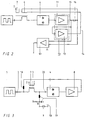
- a square wave voltage generator 1 which has a series capacitor 2 and the secondary winding 3 is connected to an evaluation circuit 4.
- the secondary winding 3 is wound on a soft magnetic magnetic core 5, on which there is also a compensation winding 6 and a primary winding 7.
- the evaluation circuit 4 is constructed such that it detects the positive or negative current peaks flowing through the secondary winding 3 and supplies the input of the downstream amplifier 8 with a voltage which corresponds to the mean value of the positive and negative current peaks.
- the soft magnetic magnetic core 5 has a flat magnetization characteristic, ie. H. a magnetization characteristic in which the induction increases almost linearly with the field strength over a wide range.
- a magnetization characteristic can be generated in the case of soft magnetic materials, in particular by tempering in the transverse field.
- the square-wave voltage generator 1 now supplies, via the series capacitor 2, a sawtooth-shaped voltage on the secondary winding 3, which generates an alternating current of a relatively high frequency in the secondary winding.
- the circuit is selected so that this current in the secondary winding is sufficient to alternately drive the soft magnetic magnetic core into positive or negative saturation.
- both the positive and the negative current peaks through the secondary winding 3 are of the same size.
- An evaluation circuit 4 now detects with the indicated anti-parallel diodes both the value for the positive and negative peak current and forms an average value therefrom.
- This mean value is essentially proportional to the premagnetization of the magnetic core 5 and thus proportional to the current to be measured in the primary winding 7.
- the output of the evaluation circuit 4 is connected to an amplifier 8, the output of which in turn drives a current through the compensation winding 6, which also occurs the soft magnetic magnetic core 5 is located.
- a resistor 9 is also connected in series with the compensation winding 6 and is connected to ground 10 with its second connection. A voltage drop now occurs across this resistor, which is proportional to the current in the compensation winding 6 and thus also the current in the primary winding 7 of the soft magnetic magnetic core 5. This proportionality arises because the evaluation circuit 4 with the downstream amplifier 8 controls the compensation current in such a way that the mean value of the positive and negative current peaks is equal to zero, so that there is no bias in the magnetic core 5.
- This current sensor has the advantage that even larger currents can be measured without any problems since the magnetic core 5 is not saturated by the primary current. In addition, relatively rapid changes in current can also be detected, since the magnetic core has a flat magnetization characteristic has and so in the event of sudden changes in the primary current - if the compensation current has not yet been adjusted - does not immediately saturate. The thus increasing mean value voltage enables the evaluation circuit 4 to track the compensation current quickly.
- a voltage proportional to the primary current to be measured in the primary winding 7 thus occurs at the resistor 9, but the polarity with respect to ground 10 depends on the direction of the current in the primary winding 7. If you now want to have a reference voltage that is particularly suitable for evaluation in digital display or control devices, it is desirable to have a voltage that has only one polarity (plus or minus) with respect to ground.
- a bridge amplifier arrangement 13 formed of two amplifiers 11 and 12 instead of the amplifier 8, the outputs 14 and 15 of which are connected to the connections of the compensation winding 6 (see FIG. 2). This creates a voltage across the resistor 16, which can be amplified via an additional amplifier 17 and, regardless of the direction of the current to be measured in the primary winding 7, has only a positive or a negative value with respect to ground 10.
- FIG. 3 shows an arrangement in which one does not need the compensation winding 6.
- the arrangement is essentially similar to that of FIG. 1 with the difference that the output of the amplifier 8 via a low pass, z. B. acting as a low-pass inductor 18 is connected to the leading to the square wave generator terminal of the secondary winding 3.
- the compensation current then also flows through the secondary winding 3 and from there via a low pass, for. B. a low-pass filter consisting of inductance and capacitance, and via resistor 9 to ground 10.
- Around the low-frequency compensation current Keep away from the evaluation circuit 4 is a high pass, z. B. between this and the low-pass filter 19, a further capacitor 20, turned on.
Landscapes
- Engineering & Computer Science (AREA)
- Power Engineering (AREA)
- Physics & Mathematics (AREA)
- General Physics & Mathematics (AREA)
- Measuring Instrument Details And Bridges, And Automatic Balancing Devices (AREA)
- Transformers For Measuring Instruments (AREA)
- Measurement Of Current Or Voltage (AREA)
Applications Claiming Priority (2)
| Application Number | Priority Date | Filing Date | Title |
|---|---|---|---|
| DE19618114 | 1996-05-06 | ||
| DE19618114A DE19618114A1 (de) | 1996-05-06 | 1996-05-06 | Stromkompensierter Stromsensor |
Publications (3)
| Publication Number | Publication Date |
|---|---|
| EP0806674A2 true EP0806674A2 (fr) | 1997-11-12 |
| EP0806674A3 EP0806674A3 (fr) | 1997-11-19 |
| EP0806674B1 EP0806674B1 (fr) | 2000-11-08 |
Family
ID=7793457
Family Applications (1)
| Application Number | Title | Priority Date | Filing Date |
|---|---|---|---|
| EP97106546A Expired - Lifetime EP0806674B1 (fr) | 1996-05-06 | 1997-04-21 | Capteur de courant à compensation du courant |
Country Status (4)
| Country | Link |
|---|---|
| US (1) | US6078172A (fr) |
| EP (1) | EP0806674B1 (fr) |
| JP (1) | JPH1054848A (fr) |
| DE (2) | DE19618114A1 (fr) |
Cited By (1)
| Publication number | Priority date | Publication date | Assignee | Title |
|---|---|---|---|---|
| CN101923134A (zh) * | 2010-03-22 | 2010-12-22 | 许继集团有限公司 | 数字式漏电流检测电路及其检测方法 |
Families Citing this family (8)
| Publication number | Priority date | Publication date | Assignee | Title |
|---|---|---|---|---|
| DE19844726B4 (de) * | 1998-09-29 | 2010-06-17 | Vacuumschmelze Gmbh | Stromsensor nach dem Kompensationsprinzip |
| DE19919602A1 (de) | 1999-04-29 | 2000-11-30 | Vacuumschmelze Gmbh | Stromsensor nach dem Kompensationsprinzip |
| SE525698C2 (sv) * | 2003-06-27 | 2005-04-05 | Forskarpatent I Syd Ab | Transformator med skydd mot likströmsmagnetisering förorsakad av nollföljdsström |
| JP4716030B2 (ja) * | 2006-10-23 | 2011-07-06 | Tdk株式会社 | 電流センサ |
| DE102008051561B4 (de) * | 2008-10-14 | 2013-06-20 | Vacuumschmelze Gmbh & Co. Kg | Verfahren zum Herstellen einer Stromerfassungseinrichtung |
| US9121885B2 (en) * | 2010-08-16 | 2015-09-01 | Infineon Technologies Ag | Sensor package and method of manufacturing thereof |
| FR2982674B1 (fr) * | 2011-11-10 | 2015-01-16 | Renault Sas | Procede et systeme de mesure de courant electrique |
| WO2015070345A1 (fr) * | 2013-11-12 | 2015-05-21 | The University Of Manitoba | Technique de mesure simultanée pour courant de phase, courant induit géomagnétiquement (gic) et courants transitoires dans des réseaux électriques |
Family Cites Families (14)
| Publication number | Priority date | Publication date | Assignee | Title |
|---|---|---|---|---|
| NL7108311A (fr) * | 1971-06-17 | 1972-12-19 | ||
| US4314200A (en) * | 1977-09-01 | 1982-02-02 | Bbc Brown, Boveri & Company Limited | Method and apparatus for detection of magnetization |
| JPS5591810A (en) * | 1978-12-29 | 1980-07-11 | Mitsubishi Electric Corp | Zero phase current transformer |
| US4482862A (en) * | 1982-06-10 | 1984-11-13 | The Charles Stark Draper Laboratory, Inc. | Current sensor |
| DE3443460A1 (de) * | 1984-11-29 | 1986-06-05 | ANT Nachrichtentechnik GmbH, 7150 Backnang | Strommesseinrichtung |
| NL8702471A (nl) * | 1987-10-15 | 1989-05-01 | Holec Syst & Componenten | Schakeling voor het detecteren van een asymmetrie in de magnetiseringsstroom van een magnetische modulator. |
| DE4019810C2 (de) * | 1989-06-23 | 1994-04-21 | Fuji Electric Co Ltd | Verfahren zum Nachweisen eines in einem Leiter fließenden Gleichstroms oder Wechselstroms |
| JPH03218475A (ja) * | 1989-11-06 | 1991-09-26 | Nkk Corp | 電流計測方法及びその装置 |
| DE4130999A1 (de) * | 1991-09-18 | 1993-03-25 | Vacuumschmelze Gmbh | Stromsensor nach dem kompensationsprinzip |
| FI90142C (fi) * | 1992-04-02 | 1993-12-27 | Abb Stroemberg Drives Oy | Enligt kompensationsprincip fungerande maetomvandlare foer stroem |
| DE4229948A1 (de) * | 1992-09-08 | 1994-03-10 | Vacuumschmelze Gmbh | Hysteresefreier Stromsensor |
| US5508606A (en) * | 1994-04-25 | 1996-04-16 | Eaton Corporation | Direct current sensor |
| US5811965A (en) * | 1994-12-28 | 1998-09-22 | Philips Electronics North America Corporation | DC and AC current sensor having a minor-loop operated current transformer |
| DE29507675U1 (de) * | 1995-05-09 | 1995-06-29 | Siemens AG, 80333 München | Kompensationsstromwandlung |
-
1996
- 1996-05-06 DE DE19618114A patent/DE19618114A1/de not_active Withdrawn
-
1997
- 1997-04-21 DE DE59702588T patent/DE59702588D1/de not_active Expired - Lifetime
- 1997-04-21 EP EP97106546A patent/EP0806674B1/fr not_active Expired - Lifetime
- 1997-04-28 JP JP9122871A patent/JPH1054848A/ja active Pending
- 1997-05-06 US US08/851,648 patent/US6078172A/en not_active Expired - Fee Related
Cited By (2)
| Publication number | Priority date | Publication date | Assignee | Title |
|---|---|---|---|---|
| CN101923134A (zh) * | 2010-03-22 | 2010-12-22 | 许继集团有限公司 | 数字式漏电流检测电路及其检测方法 |
| CN101923134B (zh) * | 2010-03-22 | 2013-01-09 | 许继集团有限公司 | 数字式漏电流检测电路及其检测方法 |
Also Published As
| Publication number | Publication date |
|---|---|
| DE59702588D1 (de) | 2000-12-14 |
| JPH1054848A (ja) | 1998-02-24 |
| DE19618114A1 (de) | 1997-11-13 |
| EP0806674B1 (fr) | 2000-11-08 |
| EP0806674A3 (fr) | 1997-11-19 |
| US6078172A (en) | 2000-06-20 |
Similar Documents
| Publication | Publication Date | Title |
|---|---|---|
| DE68924112T2 (de) | Stromsensor. | |
| DE69207223T2 (de) | Vorrichtung zum Messen von Strömen | |
| EP0691544B1 (fr) | Capteur de courant utilisant le principe de compensation | |
| DE3884554T2 (de) | Schaltung zum Nachweis der Magnetisierungsstromasymmetrie eines magnetischen Modulators. | |
| EP0132745B1 (fr) | Dispositif de mesure de courants continus | |
| EP0510376B1 (fr) | Circuit magnétique pour sonde de courant selon principe de compensation | |
| DE3040316C2 (de) | Verfahren und Vorrichtung zur kontaktlosen Messung von Gleich- und Wechselströmen, insbesondere von Strom-Augenblickswerten | |
| EP0806674A2 (fr) | Capteur de courant à compensation du courant | |
| EP0960342B1 (fr) | Detecteur de courant avec circuit generateur auto-oscillant | |
| DE3715789C2 (fr) | ||
| DE29714612U1 (de) | Strom-Meßeinrichtung | |
| DE102021104752A1 (de) | Stromsensor für die berührungslose strommessung | |
| EP0348747A2 (fr) | Arrangement de circuit pour capteur capacitif différentiel | |
| DE3424041C2 (fr) | ||
| EP0538578B1 (fr) | Capteur de courant selon le principe de la compensation | |
| DE3732064C2 (fr) | ||
| DE2834499C2 (de) | Schaltungsanordnung zum potentialfreien Messen von Strömen oder Spannungen | |
| DE102004056384A1 (de) | Verfahren zur Offseteliminierung aus Signalen magnetoresistiver Sensoren | |
| DE2944502C2 (fr) | ||
| EP0897542B1 (fr) | Detecteur de courant, notamment pour courants de faible intensite | |
| EP3252480B1 (fr) | Dispositif de mesure et procédé de mesure de courant | |
| DE102023116475A1 (de) | Stromsensor mit frequenzregelung | |
| DE19844729A1 (de) | Stromsensor | |
| DD222133A1 (de) | Gleichstrommesseinrichtung | |
| DE3313777A1 (de) | Magnetdetektorschaltung |
Legal Events
| Date | Code | Title | Description |
|---|---|---|---|
| PUAI | Public reference made under article 153(3) epc to a published international application that has entered the european phase |
Free format text: ORIGINAL CODE: 0009012 |
|
| PUAL | Search report despatched |
Free format text: ORIGINAL CODE: 0009013 |
|
| AK | Designated contracting states |
Kind code of ref document: A2 Designated state(s): CH DE DK FI FR GB IT LI SE |
|
| AK | Designated contracting states |
Kind code of ref document: A3 Designated state(s): CH DE DK FI FR GB IT LI SE |
|
| 17P | Request for examination filed |
Effective date: 19971218 |
|
| 17Q | First examination report despatched |
Effective date: 19980511 |
|
| GRAG | Despatch of communication of intention to grant |
Free format text: ORIGINAL CODE: EPIDOS AGRA |
|
| GRAG | Despatch of communication of intention to grant |
Free format text: ORIGINAL CODE: EPIDOS AGRA |
|
| GRAH | Despatch of communication of intention to grant a patent |
Free format text: ORIGINAL CODE: EPIDOS IGRA |
|
| GRAH | Despatch of communication of intention to grant a patent |
Free format text: ORIGINAL CODE: EPIDOS IGRA |
|
| GRAA | (expected) grant |
Free format text: ORIGINAL CODE: 0009210 |
|
| AK | Designated contracting states |
Kind code of ref document: B1 Designated state(s): CH DE DK FI FR GB IT LI SE |
|
| PG25 | Lapsed in a contracting state [announced via postgrant information from national office to epo] |
Ref country code: IT Free format text: LAPSE BECAUSE OF FAILURE TO SUBMIT A TRANSLATION OF THE DESCRIPTION OR TO PAY THE FEE WITHIN THE PRESCRIBED TIME-LIMIT;WARNING: LAPSES OF ITALIAN PATENTS WITH EFFECTIVE DATE BEFORE 2007 MAY HAVE OCCURRED AT ANY TIME BEFORE 2007. THE CORRECT EFFECTIVE DATE MAY BE DIFFERENT FROM THE ONE RECORDED. Effective date: 20001108 Ref country code: GB Free format text: LAPSE BECAUSE OF FAILURE TO SUBMIT A TRANSLATION OF THE DESCRIPTION OR TO PAY THE FEE WITHIN THE PRESCRIBED TIME-LIMIT Effective date: 20001108 Ref country code: FR Free format text: LAPSE BECAUSE OF FAILURE TO SUBMIT A TRANSLATION OF THE DESCRIPTION OR TO PAY THE FEE WITHIN THE PRESCRIBED TIME-LIMIT Effective date: 20001108 Ref country code: FI Free format text: LAPSE BECAUSE OF FAILURE TO SUBMIT A TRANSLATION OF THE DESCRIPTION OR TO PAY THE FEE WITHIN THE PRESCRIBED TIME-LIMIT Effective date: 20001108 |
|
| REG | Reference to a national code |
Ref country code: CH Ref legal event code: EP |
|
| REF | Corresponds to: |
Ref document number: 59702588 Country of ref document: DE Date of ref document: 20001214 |
|
| PG25 | Lapsed in a contracting state [announced via postgrant information from national office to epo] |
Ref country code: SE Free format text: LAPSE BECAUSE OF FAILURE TO SUBMIT A TRANSLATION OF THE DESCRIPTION OR TO PAY THE FEE WITHIN THE PRESCRIBED TIME-LIMIT Effective date: 20010208 Ref country code: DK Free format text: LAPSE BECAUSE OF FAILURE TO SUBMIT A TRANSLATION OF THE DESCRIPTION OR TO PAY THE FEE WITHIN THE PRESCRIBED TIME-LIMIT Effective date: 20010208 |
|
| EN | Fr: translation not filed | ||
| GBV | Gb: ep patent (uk) treated as always having been void in accordance with gb section 77(7)/1977 [no translation filed] |
Effective date: 20001108 |
|
| PG25 | Lapsed in a contracting state [announced via postgrant information from national office to epo] |
Ref country code: LI Free format text: LAPSE BECAUSE OF NON-PAYMENT OF DUE FEES Effective date: 20010520 Ref country code: CH Free format text: LAPSE BECAUSE OF NON-PAYMENT OF DUE FEES Effective date: 20010520 |
|
| PLBE | No opposition filed within time limit |
Free format text: ORIGINAL CODE: 0009261 |
|
| STAA | Information on the status of an ep patent application or granted ep patent |
Free format text: STATUS: NO OPPOSITION FILED WITHIN TIME LIMIT |
|
| 26N | No opposition filed | ||
| REG | Reference to a national code |
Ref country code: CH Ref legal event code: PL |
|
| PGFP | Annual fee paid to national office [announced via postgrant information from national office to epo] |
Ref country code: DE Payment date: 20120524 Year of fee payment: 16 |
|
| PG25 | Lapsed in a contracting state [announced via postgrant information from national office to epo] |
Ref country code: DE Free format text: LAPSE BECAUSE OF NON-PAYMENT OF DUE FEES Effective date: 20131101 |
|
| REG | Reference to a national code |
Ref country code: DE Ref legal event code: R119 Ref document number: 59702588 Country of ref document: DE Effective date: 20131101 |