EP0806672A2 - Procédé et appareil pour la manipulation d'un échantillon - Google Patents
Procédé et appareil pour la manipulation d'un échantillon Download PDFInfo
- Publication number
- EP0806672A2 EP0806672A2 EP97303093A EP97303093A EP0806672A2 EP 0806672 A2 EP0806672 A2 EP 0806672A2 EP 97303093 A EP97303093 A EP 97303093A EP 97303093 A EP97303093 A EP 97303093A EP 0806672 A2 EP0806672 A2 EP 0806672A2
- Authority
- EP
- European Patent Office
- Prior art keywords
- container
- sample
- cuvette
- needle
- cuvettes
- Prior art date
- Legal status (The legal status is an assumption and is not a legal conclusion. Google has not performed a legal analysis and makes no representation as to the accuracy of the status listed.)
- Withdrawn
Links
- 238000000034 method Methods 0.000 title claims abstract description 9
- 238000006243 chemical reaction Methods 0.000 claims abstract description 9
- 206010053567 Coagulopathies Diseases 0.000 claims abstract description 5
- 230000035602 clotting Effects 0.000 claims abstract description 5
- 239000008280 blood Substances 0.000 claims abstract description 3
- 210000004369 blood Anatomy 0.000 claims abstract description 3
- 239000012530 fluid Substances 0.000 claims description 28
- 238000005086 pumping Methods 0.000 claims description 3
- 239000000126 substance Substances 0.000 claims 6
- 230000008878 coupling Effects 0.000 claims 1
- 238000010168 coupling process Methods 0.000 claims 1
- 238000005859 coupling reaction Methods 0.000 claims 1
- 238000011156 evaluation Methods 0.000 claims 1
- 238000003780 insertion Methods 0.000 claims 1
- 230000037431 insertion Effects 0.000 claims 1
- 238000012360 testing method Methods 0.000 abstract description 44
- 239000003153 chemical reaction reagent Substances 0.000 abstract description 37
- 230000023597 hemostasis Effects 0.000 abstract description 3
- 239000000872 buffer Substances 0.000 description 9
- 239000007788 liquid Substances 0.000 description 9
- 238000001514 detection method Methods 0.000 description 8
- 230000006870 function Effects 0.000 description 5
- 230000006835 compression Effects 0.000 description 4
- 238000007906 compression Methods 0.000 description 4
- 238000012545 processing Methods 0.000 description 4
- 238000012795 verification Methods 0.000 description 4
- 238000010586 diagram Methods 0.000 description 3
- 239000000243 solution Substances 0.000 description 3
- 238000012546 transfer Methods 0.000 description 3
- 239000002699 waste material Substances 0.000 description 3
- 108010049003 Fibrinogen Proteins 0.000 description 2
- 102000008946 Fibrinogen Human genes 0.000 description 2
- 108090000190 Thrombin Proteins 0.000 description 2
- 238000003556 assay Methods 0.000 description 2
- 238000004891 communication Methods 0.000 description 2
- 238000001816 cooling Methods 0.000 description 2
- 239000012895 dilution Substances 0.000 description 2
- 238000010790 dilution Methods 0.000 description 2
- 229940012952 fibrinogen Drugs 0.000 description 2
- 230000005484 gravity Effects 0.000 description 2
- 238000010438 heat treatment Methods 0.000 description 2
- 230000033001 locomotion Effects 0.000 description 2
- 239000000203 mixture Substances 0.000 description 2
- 230000003287 optical effect Effects 0.000 description 2
- 230000002572 peristaltic effect Effects 0.000 description 2
- 239000004033 plastic Substances 0.000 description 2
- 230000037452 priming Effects 0.000 description 2
- 238000003756 stirring Methods 0.000 description 2
- 229960004072 thrombin Drugs 0.000 description 2
- PGOHTUIFYSHAQG-LJSDBVFPSA-N (2S)-6-amino-2-[[(2S)-5-amino-2-[[(2S)-2-[[(2S)-2-[[(2S)-2-[[(2S)-4-amino-2-[[(2S)-2-[[(2S)-2-[[(2S)-2-[[(2S)-2-[[(2S)-5-amino-2-[[(2S)-5-amino-2-[[(2S)-2-[[(2S)-2-[[(2S)-2-[[(2S,3R)-2-[[(2S)-5-amino-2-[[(2S)-2-[[(2S)-2-[[(2S,3R)-2-[[(2S)-2-[[(2S)-2-[[(2S)-2-[[(2S)-2-[[(2S)-5-amino-2-[[(2S)-1-[(2S,3R)-2-[[(2S)-2-[[(2S)-2-[[(2R)-2-[[(2S)-2-[[(2S)-2-[[2-[[(2S)-2-[[(2S)-2-[[(2S)-2-[[(2S)-1-[(2S)-2-[[(2S)-2-[[(2S)-2-[[(2S)-2-amino-4-methylsulfanylbutanoyl]amino]-3-(1H-indol-3-yl)propanoyl]amino]-5-carbamimidamidopentanoyl]amino]propanoyl]pyrrolidine-2-carbonyl]amino]-3-methylbutanoyl]amino]-4-methylpentanoyl]amino]-4-methylpentanoyl]amino]acetyl]amino]-3-hydroxypropanoyl]amino]-4-methylpentanoyl]amino]-3-sulfanylpropanoyl]amino]-4-methylsulfanylbutanoyl]amino]-5-carbamimidamidopentanoyl]amino]-3-hydroxybutanoyl]pyrrolidine-2-carbonyl]amino]-5-oxopentanoyl]amino]-3-hydroxypropanoyl]amino]-3-hydroxypropanoyl]amino]-3-(1H-imidazol-5-yl)propanoyl]amino]-4-methylpentanoyl]amino]-3-hydroxybutanoyl]amino]-3-(1H-indol-3-yl)propanoyl]amino]-5-carbamimidamidopentanoyl]amino]-5-oxopentanoyl]amino]-3-hydroxybutanoyl]amino]-3-hydroxypropanoyl]amino]-3-carboxypropanoyl]amino]-3-hydroxypropanoyl]amino]-5-oxopentanoyl]amino]-5-oxopentanoyl]amino]-3-phenylpropanoyl]amino]-5-carbamimidamidopentanoyl]amino]-3-methylbutanoyl]amino]-4-methylpentanoyl]amino]-4-oxobutanoyl]amino]-5-carbamimidamidopentanoyl]amino]-3-(1H-indol-3-yl)propanoyl]amino]-4-carboxybutanoyl]amino]-5-oxopentanoyl]amino]hexanoic acid Chemical compound CSCC[C@H](N)C(=O)N[C@@H](Cc1c[nH]c2ccccc12)C(=O)N[C@@H](CCCNC(N)=N)C(=O)N[C@@H](C)C(=O)N1CCC[C@H]1C(=O)N[C@@H](C(C)C)C(=O)N[C@@H](CC(C)C)C(=O)N[C@@H](CC(C)C)C(=O)NCC(=O)N[C@@H](CO)C(=O)N[C@@H](CC(C)C)C(=O)N[C@@H](CS)C(=O)N[C@@H](CCSC)C(=O)N[C@@H](CCCNC(N)=N)C(=O)N[C@@H]([C@@H](C)O)C(=O)N1CCC[C@H]1C(=O)N[C@@H](CCC(N)=O)C(=O)N[C@@H](CO)C(=O)N[C@@H](CO)C(=O)N[C@@H](Cc1cnc[nH]1)C(=O)N[C@@H](CC(C)C)C(=O)N[C@@H]([C@@H](C)O)C(=O)N[C@@H](Cc1c[nH]c2ccccc12)C(=O)N[C@@H](CCCNC(N)=N)C(=O)N[C@@H](CCC(N)=O)C(=O)N[C@@H]([C@@H](C)O)C(=O)N[C@@H](CO)C(=O)N[C@@H](CC(O)=O)C(=O)N[C@@H](CO)C(=O)N[C@@H](CCC(N)=O)C(=O)N[C@@H](CCC(N)=O)C(=O)N[C@@H](Cc1ccccc1)C(=O)N[C@@H](CCCNC(N)=N)C(=O)N[C@@H](C(C)C)C(=O)N[C@@H](CC(C)C)C(=O)N[C@@H](CC(N)=O)C(=O)N[C@@H](CCCNC(N)=N)C(=O)N[C@@H](Cc1c[nH]c2ccccc12)C(=O)N[C@@H](CCC(O)=O)C(=O)N[C@@H](CCC(N)=O)C(=O)N[C@@H](CCCCN)C(O)=O PGOHTUIFYSHAQG-LJSDBVFPSA-N 0.000 description 1
- 239000004793 Polystyrene Substances 0.000 description 1
- 108010094028 Prothrombin Proteins 0.000 description 1
- 102100027378 Prothrombin Human genes 0.000 description 1
- 108010000499 Thromboplastin Proteins 0.000 description 1
- 102000002262 Thromboplastin Human genes 0.000 description 1
- 238000004458 analytical method Methods 0.000 description 1
- 230000033228 biological regulation Effects 0.000 description 1
- 230000015572 biosynthetic process Effects 0.000 description 1
- 239000007853 buffer solution Substances 0.000 description 1
- 238000004140 cleaning Methods 0.000 description 1
- 230000015271 coagulation Effects 0.000 description 1
- 238000005345 coagulation Methods 0.000 description 1
- 238000012790 confirmation Methods 0.000 description 1
- 230000001276 controlling effect Effects 0.000 description 1
- 238000013500 data storage Methods 0.000 description 1
- 238000011010 flushing procedure Methods 0.000 description 1
- 238000000338 in vitro Methods 0.000 description 1
- 239000002184 metal Substances 0.000 description 1
- 238000000424 optical density measurement Methods 0.000 description 1
- 230000000737 periodic effect Effects 0.000 description 1
- 229920002223 polystyrene Polymers 0.000 description 1
- 229940039716 prothrombin Drugs 0.000 description 1
- 238000010926 purge Methods 0.000 description 1
- 230000001105 regulatory effect Effects 0.000 description 1
- 238000005070 sampling Methods 0.000 description 1
- 230000035945 sensitivity Effects 0.000 description 1
- XLYOFNOQVPJJNP-UHFFFAOYSA-N water Substances O XLYOFNOQVPJJNP-UHFFFAOYSA-N 0.000 description 1
Images


Classifications
-
- G—PHYSICS
- G01—MEASURING; TESTING
- G01N—INVESTIGATING OR ANALYSING MATERIALS BY DETERMINING THEIR CHEMICAL OR PHYSICAL PROPERTIES
- G01N35/00—Automatic analysis not limited to methods or materials provided for in any single one of groups G01N1/00 - G01N33/00; Handling materials therefor
- G01N35/02—Automatic analysis not limited to methods or materials provided for in any single one of groups G01N1/00 - G01N33/00; Handling materials therefor using a plurality of sample containers moved by a conveyor system past one or more treatment or analysis stations
-
- G—PHYSICS
- G01—MEASURING; TESTING
- G01N—INVESTIGATING OR ANALYSING MATERIALS BY DETERMINING THEIR CHEMICAL OR PHYSICAL PROPERTIES
- G01N33/00—Investigating or analysing materials by specific methods not covered by groups G01N1/00 - G01N31/00
- G01N33/48—Biological material, e.g. blood, urine; Haemocytometers
- G01N33/483—Physical analysis of biological material
- G01N33/487—Physical analysis of biological material of liquid biological material
- G01N33/49—Blood
- G01N33/4905—Determining clotting time of blood
-
- G—PHYSICS
- G01—MEASURING; TESTING
- G01N—INVESTIGATING OR ANALYSING MATERIALS BY DETERMINING THEIR CHEMICAL OR PHYSICAL PROPERTIES
- G01N35/00—Automatic analysis not limited to methods or materials provided for in any single one of groups G01N1/00 - G01N33/00; Handling materials therefor
- G01N35/00584—Control arrangements for automatic analysers
- G01N35/00594—Quality control, including calibration or testing of components of the analyser
- G01N35/00613—Quality control
- G01N35/00663—Quality control of consumables
- G01N2035/00673—Quality control of consumables of reagents
Definitions
- the present invention relates to a method and apparatus for use in handling a sample.
- the present invention relates to a hemostasis analyzer system useful for measuring clotting times on samples of human plasma.
- Analyses for Prothrombin Time (PT), Activated Partial Thromboplastin Time (aPTT), Thrombin Clotting Time (TCT), Fibrinogen and Factor Assays may be performed using this invention. Additional tests may be performed if data is provided as an input to the system. The system is intended for in-vitro diagnostic use.
- the system automatically transfers samples from test tubes to cuvettes, automatically prepares dilutions and mixtures of samples and reagents, incubates the mixtures and provides optical density measurements of the reaction between the sample and the reagent.
- Multiple reagent pumps deliver chilled reagents such as for PT, aPTT, TCT (Thrombin Clotting Time), Fibrinogen, and Factor Assays (Factors II, V, VII, VIII, IX, X, XI and XII).
- the invention has three primary parts which are a computer, a sample handler and an optics handler.
- the computer generally identified as the CPU controls the operation of the entire system.
- the sample handler performs the automated functions necessary to prepare the raw samples for testing.
- the optics handler controls the processing of the samples with reagents and optically obtains the results.
- test tubes each with a stopper at the top and bar codes on the side, are loaded into test tube racks.
- the system reads the bar codes from the test tubes although the system permits manual data input.
- the system determines whether or not a test tube is present in the test tube rack, ensures that the reagent vials contain proper reagents for the desired test, and automatically primes the pump assembly.
- a liquid detection system obtains samples from the test tubes, with the samples being withdrawn via a needle.
- a cuvette carousel will release one cuvette and confirm that the cuvette is properly oriented and positioned to receive the sample from the needle.
- the cuvette is automatically transported to the optics handler which confirms the presence of a cuvette.
- reagents are placed in the cuvette and the optics detects when reactions (coagulation) occur in the cuvettes. These reactions are timed.
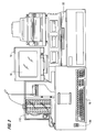
- the system 10 in basic form includes a computer (sometimes identified as a CPU) 12 including a monitor 14, a primary display device 16, a keyboard 19, a sample handler 100 and an optics handler 200.
- the physical arrangement of the system 10 is illustrated in greater detail in Figure 2, including the touch screen display 16, a printer 17, a disk drive, system power switch 20, secondary display 22, and a carousel 110.
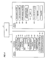
- Various functional units of the analyzer are shown in block diagrammatic form in Figure 3 including an 8-channel optical controller 24, a 4-channel temperature controller 26, a sample handler (controlling sample delivery and transport), three independent motor control modules 28, and the computer 12 for user interface and data storage.
- the temperature controller 26 includes a display 22, an incubator heater 32, an optics heater 34, a factor cooler 36 and a reagent cooler 38.
- "Y" and "Z" position encoders 40, 42 and a fluid sensor 44 are used by the sample handler to withdraw exact sample amounts from test tubes, and deposit samples into a cuvette using a needle 118.
- a diluter 46 performs the dilutions required by each type of test.
- Manual user input is through the touch screen 16 and keyboard 19 of Figure 2 including selection of the specific test, starting or stopping automatic sequence of operations, priming or purging pumps, etc. Data such as identification of the hospital patient may be entered, for example through a keyboard 19, bar code reader 50, or a network.
- the processor or computer 12 which operates the system is preferably comprised of cards located within the card cage 52.
- the preferred cards within the card cage include a touch screen interface, b) embedded PC, c) motor controller (1-8), d) motor controller (9-16), e) motor controller (17-24), f) sample handler, g) temperature controller, and h) optics controller as shown in Figure 3.
- the card cage contains the other circuits for operating the apparatus of the present invention.
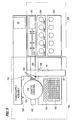
- the sample handler system 100 contains racks 102, 104, the bar code reader 50 referred to previously, a test tube detector 108, a cuvette carousel 110 with vertical racks of cuvettes, an arm 114 with a related fluid sensor 44 and a needle 118, a waste container sensor system 120, syringe motor 122, peristaltic pumps 124, cuvette delivery system 126 and a cuvette orientation verification system 128.
- the sample handler controls motion in the Y and Z coordinate planes moving the test tube racks 102 and the factor racks 104 in the X direction to position test tubes beneath the arm assembly 114 and in particular, the needle 118 of the arm assembly.
- the arm assembly moves the needle in the Y and Z planes.
- the sample handler includes peristaltic pumps 124 and the syringe 121 with the accompanying syringe motor 122.
- peristaltic pumps 124 Preferably there are two pumps, one for flushing the inside of the needle through the syringe system and the second for pumping water to a wash basin 130 that is used to clean the outside of the needle.
- the wash basin In the wash basin, the needle is cleaned with a continuous flow of cleaning solution.
- the cuvette carousel 110 holds ten stacks of ten cuvettes each.
- the cuvette delivery assembly 126 includes those parts which allow the cuvette to be fed ultimately from the carousel to the chute and to the optics handler.
- the cuvette verification/orientation system 128 sense that the cuvette is in the proper position and orientation before the cuvette is permitted to receive samples and reagents.
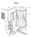
- the carousel 110 includes the series of vertical racks or channels 140 and two partially-full racks, with cuvettes 112, are illustrated.
- the factor/buffer rack 104 holds the factors (chemical reagents) and buffers that are necessary in performing the various tests.
- the factors/buffers are maintained in bottles 105 in a position such that the needle, controlled by the arm assembly, may obtain the necessary quantities of factors or buffers.
- the test tube rack 102 holds the blood samples in test tubes 103.
- the bar code reader 50 which is interfaced to the sample handler will input data from bar coded labels on the test tubes 103 and confirms the presence or absence of light from the bar code to determine whether a test tube 103 is present.
- the fluid sensor 44 together with the arm assembly and needle, sense fluid and assist in obtaining or withdrawing the proper amount of fluid from a test tube 103 in the tube rack 104, or from a factor bottle or buffer bottle in the factor/buffer rack 104.
- a syringe 121 and a syringe motor 122 are shown for handling the exact quantities of fluid that the needle will withdraw from the test tubes or factor or buffer solutions in the factor/buffer racks.
- the syringe and syringe motor system is extremely precise and is connected to the needle through plastic piping.
- the cuvette carousel 110 which is covered by a cuvette carousel lid 134, holds vertical racks of cuvettes.
- the cuvette carousel is circular and is loaded with empty cuvettes from one side and the cuvettes are discharged from the opposite side for use by the system.
- the pumps 124 have fittings and delivery tubes 136, one of which is connected to supply the wash basin 130 which washes the outside of the needle. Waste tubes 138 transfer fluid away from the sample handler.
- the wash basin forces a solution up against gravity and the needle is lowered into the running solution.
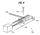
- the test tube detector system 108 for determining the presence or absence of a test tube 103 uses bar code reader 50 which reads bar codes on the factors/buffers bottles 105 and on patient test tubes 103.
- the light from the bar code reader is used to determine the presence or absence of a test tube and the test tube detection system 108 includes a photodetector 144. If there are no obstructions between the light source and a photodetector, the light beam 148 from the bar code reader is received and a voltage threshold is set in the photodetector. This is referred to as initializing the bar code reader.
- a test tube rack moves in position, if a bar code cannot be read and the photodetector receives the same amount of light as when initialized, then a tube is "not" present. However, if, the photodetector receives a lesser amount of light, then a test tube is present.
- the fluid sensor or level detector system 44 operates in conjunction with the arm 114 and needle 118.
- the fluid level detector operates in the RF range and only the needle makes contact with the fluid.
- the needle 118 pierces the rubber stopper on the tube and then functions as the sensor.
- the preferred fluid detector is based on a radio frequency CMOS oscillator 150 having an output frequency optimally at 4 mhz. This frequency is sensitive to fluid and lacks sensitivity to surrounding metal used to build the instrument in which the fluid level detector is utilized. Variations from this frequency are possible.
- the oscillator output is coupled to the sample needle via a 50 ohm shielded cable.
- the shield extends to the sample needle thus reducing radiated RF energy to a few microwatts because of the needle length which is extremely short.
- the oscillator output is capacitively coupled 152 to a rectifier, filtered, and then fed into a comparator 154.
- the sine wave oscillator voltage output drops.
- the comparator 154 is sampling, causing it to compare.
- the comparator reference voltage 156 is set via a resistor divider and the comparator compare point is set according to the depth desired in the sample tube.
- a buffered analog output voltage 158 is derived from the rectified oscillator voltage which is fed into an analog to digital converter. This allows the raw data from the level sensor to be interpreted by software to greatly increase the dynamic range of the sensor.
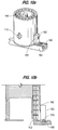
- the delivery system 126 ejects or releases a cuvette 112 from the carousel or turret 110.
- a plunger 160 and compression spring 162 are positioned in a spring block housing 163 which is mounted to the outside of the carousel 110. The plunger moves laterally from a first position under a rack 140 in the carousel ( Figure 10b) to a second position inwardly of the rack ( Figure 10c). It is necessary to eliminate the weight of multiple, vertically oriented cuvettes from the bottom cuvette.
- the plunger 160 initially prevents the release of the cuvettes.
- the plunger includes a roller bearing 170 which contacts an actuator rod 166 in the spring block housing 163. In this position, the compression spring 162 in the housing is moved out of contact with the vertical column of cuvettes.
- the roller bearing 170 moves clear of the actuator rod 166.
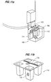
- the compression spring 162 biases the actuator rod into the downward position ( Figure 10c) and moves toward the vertical rack of cuvettes to contact the second cuvette from the bottom and urges the second cuvette against the carousel rack. This holds the second cuvette, and all the cuvettes above the second cuvette, in the rack while relieving the pressure on the bottom cuvette. Then only the bottom cuvette is released into a cuvette chute 164.
- positive cuvette orientation system 128 includes two photodetectors 172, 174 positioned at right angles to each other with one photodetector 172 positioned above the chute 164 and the other photodetector 174 positioned adjacent the chute.
- the individual cuvette 112 includes a first portion 176 on the flat top of the cuvette and a second portion 178 on a side wall of the cuvette. As the cuvette is discharged from the carousel and moves into the chute 164, the cuvette moves beneath a first photodetector 172 which reflects a beam of light off the flat top portion 176 of the cuvette top surface.
- a transverse beam (across the direction of travel within the chute) is generated from the second photodetector which is reflected back from the side wall 178 only if the cuvette is properly aligned. If both photodetectors receive positive signals, this is a confirmation that a cuvette is properly oriented. Any other condition generates an error signal to prevent any attempt at placing samples into the cuvette.
- the optics handler 200 includes a variety of subsystems which perform various functions including reading sample optics 202 and calculating tests 204.
- the optics handler controls the pump assembly motors 206 for pumping reagents, the stir motors 208 for stirring the reagents, the transport belt 210, the vial level detectors 212, heaters and coolers 216.
- the optics handler 200 performs the clot analyzing functions of the invention.
- a delivery or transport belt 210 receives cuvettes from the chute 164 and moves the cuvettes.
- the delivery belt uses photodetectors to verify the proper positioning of the cuvettes along the belt as is conventional.
- the cuvettes While the cuvettes are moved along this belt, the cuvettes are being heated and it is preferred that the cuvettes and reagents reach a stable and optimum temperature of 37°C before the tests are actually performed.
- the belt is moved along at the speed necessary for the desired test and thus the speed is controlled by the laboratory technician selecting the specific test. It is within the skill of the art to program the transport speed based upon the test selected, such information being easily stored in a look up table. Thus the belt speed changes depending on the test which has been selected, and the time that the cuvette travels along the belt will change depending upon the test and user inputs.
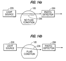
- a non-invasive level detector for determining the levels of reagent bottles uses the properties of light and occlusion and works with both opaque and clear liquids.
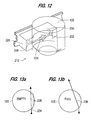
- an optic block 226 is positioned adjacent a bottle or vat 105 of reagent.
- a LED transmitter 228 and photodetector 230 are used in conjunction with a collimator hole 232 formed in the optic block.
- the narrow light beam 234, such as from an LED or HeNE laser is directed through a chord of a clear polystyrene container or bottle 105.
- the beam of light cannot travel through the diameter of the vat but must be off-center, e.g., as a chord 235 of a circle in Figure 13a.
- the beam deflects as at 236 due to the optical density of the liquid.
- the deflection (or diffraction) diverts the beam away from the photodetector 230 at the opposite side of the vat and the photodetector will not receive the beam.
- the photodetector receives the beam of light, i.e., the light beam is not deflected. Therefore, the preferred detection system indicates the absence of a vat and the presence or absence of fluid if the vat is present.
- Figure 12 illustrates the physical arrangement of the liquid level detection system
- Figures 13a and 14a indicate the presence of a container 105 which is empty (or the absence of a container)
- Figures 13b and 14b indicate the presence of liquid at the vertical level (height) of the detector.
- the height of the detector may be selected to insure sufficient fluid for the quantity of tests which can be performed without further intervention by the laboratory technician.
- the pump assembly system 206 transfers fluids from the reagent vials or bottles 105 to the cuvettes.
- the volume of reagent transferred to the cuvettes is preferably an exact amount of reagent which is accomplished by using exact volume tubing, that is, plastic pipes which have been tested so that a certain length of the pipe holds exactly the volume of reagent that is needed for a particular test.
- Autopriming fills the delivery tubes with reagent.
- a standard cuvette 112 with four wells is discharged from the carousel and transported by the belt 210 until two of the wells are positioned under two delivery tubes of the specified reagent. At this area is a standard photodetection system used for timing the formation of a clot.
- the system initializes or "nulls" the light change caused by the empty cuvette in the optics path.
- a predetermined threshold is set by the software for detecting converted analog readings from the optics detector. This is referred to as a z-axis threshold value for the photodetection system, the z-axis referring to the vertical axis when the system is viewed from the front as is conventional.
- the associated pump 218 turns for a predetermined number of cycles, moving fluid into the first delivery tube. After a few revolutions any fluid (reagent) is now ejected into the cuvette.
- the photodetection system checks for the presence of fluid in the first cuvette well by measuring the change of light intensity at the threshold z-axis value.
- first reagent pump has been primed so that the desired amount of reagent (using the exact volume delivery tube) will be pumped into a subsequent cuvette when an actual sample is being tested. Then the autopriming is repeated for each reagent. The reagents used for priming are then discarded into the waste area 120.
- Thermal control in this invention is achieved using an embedded algorithm with a microprocessor based control unit to monitor and adjust the temperature of the various liquids used by this invention.
- the embedded algorithm requires:
- the "current temperature” variable is moved to the "previous temperature” variable and the “current temperature” is updated from the averaged value sent from the interrupt event.
- the “current direction” is computed by subtracting the "previous temperature” from the "current temperature”.
- the need to regulate is determined by comparing "current temperature" to the safety limits. Outside of the safety limits the algorithm removes all drive from the physical device and does no further function to determine regulation. If the temperature is within safety limits the algorithm determines whether to cool (drive to a lesser temperature) or heat (drive to a greater temperature) based on information provided by the external memory interface.
- error accumulator is added to insure that the maximum rate added (or subtracted) to the "pulse width value" provides smooth power addition (or subtraction) to the device under control
- the thermal control algorithm has the benefit that it can be configured to drive either heating or cooling devices, it has built in safety devices in the event of loss of sensor input, and it uses a simplified integrator/differentiator to allow for a variety of thermal masses to be regulated.
Landscapes
- Health & Medical Sciences (AREA)
- Life Sciences & Earth Sciences (AREA)
- Engineering & Computer Science (AREA)
- Chemical & Material Sciences (AREA)
- Physics & Mathematics (AREA)
- General Health & Medical Sciences (AREA)
- General Physics & Mathematics (AREA)
- Immunology (AREA)
- Pathology (AREA)
- Biochemistry (AREA)
- Biomedical Technology (AREA)
- Analytical Chemistry (AREA)
- Hematology (AREA)
- Ecology (AREA)
- Quality & Reliability (AREA)
- Biophysics (AREA)
- Molecular Biology (AREA)
- Urology & Nephrology (AREA)
- Food Science & Technology (AREA)
- Medicinal Chemistry (AREA)
- Automatic Analysis And Handling Materials Therefor (AREA)
- Investigating Or Analysing Biological Materials (AREA)
- Investigating Or Analysing Materials By Optical Means (AREA)
- Length Measuring Devices By Optical Means (AREA)
Applications Claiming Priority (2)
| Application Number | Priority Date | Filing Date | Title |
|---|---|---|---|
| US1695296P | 1996-05-06 | 1996-05-06 | |
| US16952P | 1996-05-06 |
Publications (2)
| Publication Number | Publication Date |
|---|---|
| EP0806672A2 true EP0806672A2 (fr) | 1997-11-12 |
| EP0806672A3 EP0806672A3 (fr) | 2000-04-26 |
Family
ID=21779908
Family Applications (1)
| Application Number | Title | Priority Date | Filing Date |
|---|---|---|---|
| EP97303093A Withdrawn EP0806672A3 (fr) | 1996-05-06 | 1997-05-06 | Procédé et appareil pour la manipulation d'un échantillon |
Country Status (3)
| Country | Link |
|---|---|
| US (1) | US5879628A (fr) |
| EP (1) | EP0806672A3 (fr) |
| JP (1) | JPH10206431A (fr) |
Cited By (6)
| Publication number | Priority date | Publication date | Assignee | Title |
|---|---|---|---|---|
| WO2001036981A1 (fr) * | 1999-11-12 | 2001-05-25 | F. Hoffmann-La Roche Ag | Appareil d'analyse avec support rotatif de plateaux porte-echantillons |
| US7222526B2 (en) | 2004-06-17 | 2007-05-29 | Ortho-Clinical Diagnostics, Inc | Liquid measurements using capacitive monitoring |
| CN101776583A (zh) * | 2009-01-09 | 2010-07-14 | 三星电子株式会社 | 防止平台复制的方法和系统 |
| GB2513587A (en) * | 2013-04-30 | 2014-11-05 | Stratec Biomedical Ag | Cuvette handling device |
| CN115372345A (zh) * | 2021-05-21 | 2022-11-22 | 韩国巴迪泰生物科技有限公司 | 自动体外诊断检查装置 |
| LU103248B1 (en) | 2024-02-19 | 2025-08-19 | Stratec Se | Container handling device |
Families Citing this family (76)
| Publication number | Priority date | Publication date | Assignee | Title |
|---|---|---|---|---|
| IT1286630B1 (it) * | 1996-05-16 | 1998-07-15 | Diesse Diagnostica | Una provetta per esami biologici di liquidi organici con apparecchi elettro-ottici |
| US6929953B1 (en) | 1998-03-07 | 2005-08-16 | Robert A. Levine | Apparatus for analyzing biologic fluids |
| US6723290B1 (en) * | 1998-03-07 | 2004-04-20 | Levine Robert A | Container for holding biologic fluid for analysis |
| US6495106B1 (en) * | 1998-03-24 | 2002-12-17 | Biogenex Laboratories | Automated staining apparatus |
| US6592822B1 (en) * | 1998-05-14 | 2003-07-15 | Luminex Corporation | Multi-analyte diagnostic system and computer implemented process for same |
| JP2000225334A (ja) * | 1999-02-04 | 2000-08-15 | Shimadzu Corp | 自動合成装置 |
| US6787363B2 (en) * | 1999-02-22 | 2004-09-07 | Haemoscope Corporation | Method and apparatus for hemostasis and blood management |
| US7288195B2 (en) * | 1999-05-28 | 2007-10-30 | Bio/Data Corporation | Method and apparatus for directly sampling a fluid for microfiltration |
| EP1230028B1 (fr) * | 1999-05-28 | 2008-07-16 | Bio/Data Corporation | Procede et dispositif d'echantillonnage direct d'un fluide, aux fins de microfiltration |
| US6979425B1 (en) * | 1999-10-04 | 2005-12-27 | Robodesign International, Inc. | High capacity microarray dispensing |
| US6558623B1 (en) * | 2000-07-06 | 2003-05-06 | Robodesign International, Inc. | Microarray dispensing with real-time verification and inspection |
| JP4606543B2 (ja) * | 2000-04-13 | 2011-01-05 | パナソニック株式会社 | 光学特性計測装置における被検溶液量確認方法および計測系制御方法 |
| US6442440B1 (en) * | 2000-06-24 | 2002-08-27 | Dade Behring Inc. | Computer interface module having a flat menu |
| US7025933B2 (en) * | 2000-07-06 | 2006-04-11 | Robodesign International, Inc. | Microarray dispensing with real-time verification and inspection |
| EP1337337A2 (fr) * | 2000-10-30 | 2003-08-27 | Robodesign International, Inc. | Distribution de microreseaux a haute capacite |
| US20050011582A1 (en) * | 2003-06-06 | 2005-01-20 | Haug Jeffrey S. | Fluid delivery system for a flow cytometer |
| US7163031B2 (en) * | 2004-06-15 | 2007-01-16 | Mallinckrodt Inc. | Automated dispensing system and associated method of use |
| US20060213994A1 (en) * | 2005-03-22 | 2006-09-28 | Faiz Tariq N | Barcode reading apparatus and method therefor |
| JP5119377B2 (ja) | 2005-09-26 | 2013-01-16 | キアゲン ゲゼルシャフト ミット ベシュレンクテル ハフツング | 生物試料を処理するための装置 |
| EP1767274B1 (fr) * | 2005-09-26 | 2015-09-09 | QIAGEN GmbH | Procédé pour le traitement d'un fluide |
| JP4243324B2 (ja) * | 2007-05-15 | 2009-03-25 | パナソニック株式会社 | 攪拌状態検出方法 |
| EP2020263B1 (fr) * | 2007-07-27 | 2014-05-07 | F.Hoffmann-La Roche Ag | Étiquette d'identification de l'orientation, structure porteuse de récipients de réactif et dispositif d'analyse |
| CA3170924A1 (fr) | 2007-10-02 | 2009-04-09 | Labrador Diagnostics Llc | Dispositifs modulaires a utiliser sur place et leurs utilisations |
| CN102762289B (zh) | 2009-12-18 | 2016-08-03 | 艾博特健康公司 | 生物流体分析卡盒 |
| US9199233B2 (en) | 2010-03-31 | 2015-12-01 | Abbott Point Of Care, Inc. | Biologic fluid analysis cartridge with deflecting top panel |
| WO2012092593A1 (fr) | 2010-12-30 | 2012-07-05 | Abbott Point Of Care, Inc. | Cartouche d'analyse de liquide biologique équipée d'une partie manipulation d'échantillon et d'une partie chambre d'analyse |
| CN106323875B (zh) | 2011-01-21 | 2019-07-09 | 西拉诺斯知识产权有限责任公司 | 样品使用最大化的系统和方法 |
| US9039992B2 (en) | 2011-06-06 | 2015-05-26 | Abbott Laboratories | Apparatus for closed tube sampling and open tube sampling for automated clinical analyzers |
| US8797527B2 (en) | 2011-08-24 | 2014-08-05 | Abbott Point Of Care, Inc. | Biologic fluid sample analysis cartridge |
| US8475739B2 (en) | 2011-09-25 | 2013-07-02 | Theranos, Inc. | Systems and methods for fluid handling |
| US9632102B2 (en) | 2011-09-25 | 2017-04-25 | Theranos, Inc. | Systems and methods for multi-purpose analysis |
| US20140170735A1 (en) | 2011-09-25 | 2014-06-19 | Elizabeth A. Holmes | Systems and methods for multi-analysis |
| US9664702B2 (en) | 2011-09-25 | 2017-05-30 | Theranos, Inc. | Fluid handling apparatus and configurations |
| US10012664B2 (en) | 2011-09-25 | 2018-07-03 | Theranos Ip Company, Llc | Systems and methods for fluid and component handling |
| US9810704B2 (en) | 2013-02-18 | 2017-11-07 | Theranos, Inc. | Systems and methods for multi-analysis |
| EP2809429A4 (fr) * | 2012-02-03 | 2015-10-28 | Microsonic Systems Inc | Appareil pour l'automatisation de traitement d'échantillon liquide mettant en uvre des ondes d'ultrasons |
| EP2906957A2 (fr) * | 2012-10-12 | 2015-08-19 | Koninklijke Philips N.V. | Détection optique du remplissage |
| US11545241B1 (en) | 2013-09-07 | 2023-01-03 | Labrador Diagnostics Llc | Systems and methods for analyte testing and data management |
| JP6701338B2 (ja) | 2015-08-10 | 2020-05-27 | エッセンリックス コーポレーション | ステップが簡略化され、試料が少なく、スピードアップし、使いやすい、生化学的/化学的なアッセイ装置及び方法 |
| AU2016323062A1 (en) | 2015-09-14 | 2018-04-12 | Essenlix Corp. | Device and system for analyzing a sample, particularly blood, as well as methods of using the same |
| US10132794B2 (en) | 2015-09-14 | 2018-11-20 | Essenlix Corporation | Device and system for collecting and analyzing vapor condensate, particularly exhaled breath condensate, as well as method of using the same |
| US10311569B1 (en) | 2015-12-31 | 2019-06-04 | Cerner Innovation, Inc. | Identifying liquid blood components from sensed data to monitor specimen integrity |
| US10267813B1 (en) | 2015-12-31 | 2019-04-23 | Cerner Innovation, Inc. | Monitoring specimen integrity in automated blood sample processing system |
| US10209267B1 (en) | 2015-12-31 | 2019-02-19 | Cerner Innovation, Inc. | Sample extraction and rotation device for automated blood sample processing systems |
| US10527635B1 (en) | 2015-12-31 | 2020-01-07 | Cerner Innovation, Inc. | Specimen integrity monitoring device for automated blood sample processing systems |
| CN115078351A (zh) | 2016-08-31 | 2022-09-20 | 雅培制药有限公司 | 用于评估生物样品完整性的系统、设备和相关方法 |
| JP6667052B1 (ja) | 2016-12-21 | 2020-03-18 | エッセンリックス コーポレーション | 試料を認証するためのデバイスおよび方法ならびにその使用 |
| WO2018148342A1 (fr) | 2017-02-07 | 2018-08-16 | Essenlix Corporation | Dosage et utilisation d'écoulement ouvert comprimé |
| CA3053005A1 (fr) | 2017-02-08 | 2018-08-16 | Essenlix Corporation | Collecte et manipulation d'echantillons pour analyse retardee |
| WO2018148764A1 (fr) | 2017-02-08 | 2018-08-16 | Essenlix Corporation | Manipulation moléculaire et dosage à température contrôlée |
| US12066434B2 (en) | 2017-02-08 | 2024-08-20 | Essenlix Corporation | QMAX assays and applications |
| US11927560B2 (en) | 2017-02-08 | 2024-03-12 | Essenlix Corporation | Bio/chemical material extraction and assay |
| CA3052962A1 (fr) | 2017-02-08 | 2018-08-16 | Essenlix Corp. | Dosage numerique |
| WO2018148461A1 (fr) | 2017-02-09 | 2018-08-16 | Essenlix Corp. | Dosage avec amplification |
| JP2020507770A (ja) | 2017-02-09 | 2020-03-12 | エッセンリックス コーポレーション | 比色アッセイ法 |
| EP3580565B1 (fr) | 2017-02-09 | 2024-05-29 | Essenlix Corporation | Dosage utilisant différentes hauteurs d'espacement |
| US12350680B2 (en) | 2017-02-15 | 2025-07-08 | Essenlix Corporation | Assay with rapid temperature change |
| CN120195095A (zh) | 2017-02-16 | 2025-06-24 | 上海宜晟生物科技有限公司 | 采用纹理化表面的测定方法及装置 |
| EP3638421A4 (fr) | 2017-06-12 | 2021-04-07 | Essenlix Corporation | Dosage homogène |
| CN120668916A (zh) | 2017-08-01 | 2025-09-19 | 上海宜晟生物科技有限公司 | 检查药物对微生物影响的装置和方法 |
| US11280706B2 (en) | 2017-08-01 | 2022-03-22 | Essenlix Corporation | Dilution calibration |
| WO2019028123A1 (fr) | 2017-08-01 | 2019-02-07 | Essenlix Corporation | Prélèvement, maintien et dosage d'échantillons |
| CN110869745B (zh) | 2017-08-17 | 2023-08-11 | 雅培医护站股份有限公司 | 用于执行光学测定的设备、系统和方法 |
| CN110869746B (zh) | 2017-08-17 | 2023-08-11 | 雅培医护站股份有限公司 | 利用通用电路系统执行光学和电化学测定的技术 |
| CN110892247B (zh) | 2017-08-17 | 2023-08-25 | 雅培医护站股份有限公司 | 用于执行光学和电化学测定的设备、系统和方法 |
| US12403465B2 (en) | 2017-10-11 | 2025-09-02 | Essenlix Corporation | Containing a liquid sample |
| US11393561B2 (en) | 2017-10-13 | 2022-07-19 | Essenlix Corporation | Devices and methods for authenticating a medical test and use of the same |
| US10807095B2 (en) | 2017-10-26 | 2020-10-20 | Essenlix Corporation | Making and tracking assay card |
| US11237113B2 (en) | 2017-10-26 | 2022-02-01 | Essenlix Corporation | Rapid pH measurement |
| US11609224B2 (en) | 2017-10-26 | 2023-03-21 | Essenlix Corporation | Devices and methods for white blood cell analyses |
| US11648551B2 (en) | 2017-12-12 | 2023-05-16 | Essenlix Corporation | Sample manipulation and assay with rapid temperature change |
| US11510608B2 (en) | 2017-12-14 | 2022-11-29 | Essenlix Corporation | Devices, systems, and methods for monitoring hair |
| WO2019140334A1 (fr) | 2018-01-11 | 2019-07-18 | Essenlix Corporation | Dosage homogène (ii) |
| US11885952B2 (en) | 2018-07-30 | 2024-01-30 | Essenlix Corporation | Optics, device, and system for assaying and imaging |
| JP2020051915A (ja) * | 2018-09-27 | 2020-04-02 | ウシオ電機株式会社 | 光学測定装置および光学測定方法 |
| CN115166267B (zh) * | 2022-06-21 | 2023-05-09 | 上海太阳生物技术有限公司 | 一种全自动凝血分析仪及其样本进样系统 |
Family Cites Families (17)
| Publication number | Priority date | Publication date | Assignee | Title |
|---|---|---|---|---|
| US3656473A (en) * | 1969-08-28 | 1972-04-18 | American Science & Eng Inc | Medical data processing |
| US4369361A (en) * | 1980-03-25 | 1983-01-18 | Symbol Technologies, Inc. | Portable, stand-alone, desk-top laser scanning workstation for intelligent data acquisition terminal and method of scanning |
| EP0096065B1 (fr) * | 1981-12-15 | 1986-09-03 | Beckman Instruments, Inc. | Appareil de transport de porte-echantillons |
| US4736638A (en) * | 1985-12-20 | 1988-04-12 | Beckman Instruments, Inc. | Liquid level sensor |
| US4935875A (en) * | 1987-12-02 | 1990-06-19 | Data Chem, Inc. | Chemical analyzer |
| US5098661A (en) * | 1988-11-16 | 1992-03-24 | Medical Laboratory Automation, Inc. | Coded cuvette for use in testing apparatus |
| US5045208A (en) * | 1989-10-27 | 1991-09-03 | Helena Laboratories Corporation | Column analyzer system |
| IE78906B1 (en) * | 1989-12-01 | 1998-03-11 | Akzo Nv | Sample handling system for an optical monitoring system |
| JPH0736284Y2 (ja) * | 1990-10-05 | 1995-08-16 | 東亜医用電子株式会社 | 検体容器の検体識別コード読取装置 |
| DE4203638A1 (de) * | 1992-02-08 | 1993-08-12 | Boehringer Mannheim Gmbh | Fluessigkeitstransfereinrichtung fuer ein analysegeraet |
| US5376313A (en) * | 1992-03-27 | 1994-12-27 | Abbott Laboratories | Injection molding a plastic assay cuvette having low birefringence |
| US5578269A (en) * | 1993-06-11 | 1996-11-26 | Ortho Diagnostic Systems Inc. | Automated blood analysis system with an integral centrifuge |
| US5493922A (en) * | 1993-07-09 | 1996-02-27 | Akzo N.V. | Liquid level sensing probe and control circuit |
| DE69434128T2 (de) * | 1993-08-16 | 2005-11-10 | Biomerieux, Inc. | Methode und gerät zur automatischen durchführung von analysen bezüglich thrombose und blutgerinnung |
| KR960704634A (ko) * | 1993-10-14 | 1996-10-09 | 미리암 디. 메코너헤이 | 샘플 용기 자동 처리식 원심 분리기 및 원심 분리기용 회전자(Automatic Sample Container Handling Centrifuge and a Rotor for Use Therein) |
| US5411065A (en) * | 1994-01-10 | 1995-05-02 | Kvm Technologies, Inc. | Liquid specimen transfer apparatus and method |
| US5637854A (en) * | 1995-09-22 | 1997-06-10 | Microscan Systems Incorporated | Optical bar code scanner having object detection |
-
1997
- 1997-05-01 US US08/847,225 patent/US5879628A/en not_active Expired - Fee Related
- 1997-05-06 JP JP9115779A patent/JPH10206431A/ja active Pending
- 1997-05-06 EP EP97303093A patent/EP0806672A3/fr not_active Withdrawn
Cited By (10)
| Publication number | Priority date | Publication date | Assignee | Title |
|---|---|---|---|---|
| WO2001036981A1 (fr) * | 1999-11-12 | 2001-05-25 | F. Hoffmann-La Roche Ag | Appareil d'analyse avec support rotatif de plateaux porte-echantillons |
| US7407627B1 (en) | 1999-11-12 | 2008-08-05 | Roche Diagnostics Corporation | Analyzer having a rotatable sample rack carrier |
| US7222526B2 (en) | 2004-06-17 | 2007-05-29 | Ortho-Clinical Diagnostics, Inc | Liquid measurements using capacitive monitoring |
| CN101776583A (zh) * | 2009-01-09 | 2010-07-14 | 三星电子株式会社 | 防止平台复制的方法和系统 |
| CN101776583B (zh) * | 2009-01-09 | 2014-10-15 | 三星电子株式会社 | 防止平台复制的方法和系统 |
| GB2513587A (en) * | 2013-04-30 | 2014-11-05 | Stratec Biomedical Ag | Cuvette handling device |
| US9250256B2 (en) | 2013-04-30 | 2016-02-02 | Stratec Biomedical Ag | Cuvette handling device |
| CN115372345A (zh) * | 2021-05-21 | 2022-11-22 | 韩国巴迪泰生物科技有限公司 | 自动体外诊断检查装置 |
| LU103248B1 (en) | 2024-02-19 | 2025-08-19 | Stratec Se | Container handling device |
| EP4603845A1 (fr) | 2024-02-19 | 2025-08-20 | Stratec SE | Dispositif de manipulation de récipients |
Also Published As
| Publication number | Publication date |
|---|---|
| US5879628A (en) | 1999-03-09 |
| EP0806672A3 (fr) | 2000-04-26 |
| JPH10206431A (ja) | 1998-08-07 |
Similar Documents
| Publication | Publication Date | Title |
|---|---|---|
| EP0806672A2 (fr) | Procédé et appareil pour la manipulation d'un échantillon | |
| US5270211A (en) | Sample tube entry port for a chemical analyzer | |
| EP0753745B1 (fr) | Méthode et dispositif de gestion de réactifs | |
| US5646046A (en) | Method and instrument for automatically performing analysis relating to thrombosis and hemostasis | |
| EP2293083B1 (fr) | Analyseur automatique | |
| EP2891888B1 (fr) | Dispositif d'analyse automatisé | |
| EP0714506B1 (fr) | Procede et instrument destines a effectuer automatiquement une analyse des proprietes de thrombose et d'hemostase | |
| US20100001876A1 (en) | Analyzer and analysis method | |
| CN108027380B (zh) | 自动分析装置 | |
| EP3508858A1 (fr) | Procédé de mesure d'échantillons et dispositif de mesure d'échantillons | |
| US20090292494A1 (en) | Analyzer | |
| WO2007129741A1 (fr) | Analyseur automatique | |
| US20190265264A1 (en) | Sample measuring apparatus and sample measuring method | |
| EP2019321A1 (fr) | Équipement de nettoyage et analyseur automatique | |
| EP3686605B1 (fr) | Appareil d'analyse automatique | |
| JP2011128075A (ja) | 自動分析装置、自動分析装置の検体攪拌方法および検体分注方法 | |
| JP2011163909A (ja) | 自動分析装置および分注手段の洗浄方法 | |
| EP2075587B1 (fr) | Analyseur automatique et son procédé de distribution | |
| JP7494375B2 (ja) | 自動分析装置、および自動分析装置における検体の吸引方法 | |
| JPH10115620A (ja) | 臨床用自動分析装置 | |
| JPH10232234A (ja) | 自動分析装置 | |
| EP3754327A1 (fr) | Procédé et appareil de mesure d'échantillon | |
| JP5374092B2 (ja) | 自動分析装置および血液サンプル分析方法 | |
| CN114137235A (zh) | 自动分析装置 | |
| JP2015215367A (ja) | 自動分析装置 |
Legal Events
| Date | Code | Title | Description |
|---|---|---|---|
| PUAI | Public reference made under article 153(3) epc to a published international application that has entered the european phase |
Free format text: ORIGINAL CODE: 0009012 |
|
| AK | Designated contracting states |
Kind code of ref document: A2 Designated state(s): DE FR GB IT |
|
| PUAL | Search report despatched |
Free format text: ORIGINAL CODE: 0009013 |
|
| AK | Designated contracting states |
Kind code of ref document: A3 Designated state(s): DE FR GB IT |
|
| RIC1 | Information provided on ipc code assigned before grant |
Free format text: 7G 01N 35/02 A, 7G 01N 33/483 B, 7B 01L 3/00 B, 7G 01N 35/10 B, 7G 01N 33/49 B |
|
| 17P | Request for examination filed |
Effective date: 20000621 |
|
| STAA | Information on the status of an ep patent application or granted ep patent |
Free format text: STATUS: THE APPLICATION IS DEEMED TO BE WITHDRAWN |
|
| 18D | Application deemed to be withdrawn |
Effective date: 20011201 |