EP0806527B1 - Un dispositif d'évacuation actionné par air comprimé pour appareil sanitaire - Google Patents
Un dispositif d'évacuation actionné par air comprimé pour appareil sanitaire Download PDFInfo
- Publication number
- EP0806527B1 EP0806527B1 EP97106779A EP97106779A EP0806527B1 EP 0806527 B1 EP0806527 B1 EP 0806527B1 EP 97106779 A EP97106779 A EP 97106779A EP 97106779 A EP97106779 A EP 97106779A EP 0806527 B1 EP0806527 B1 EP 0806527B1
- Authority
- EP
- European Patent Office
- Prior art keywords
- duct
- chamber
- piston
- cup
- opening
- Prior art date
- Legal status (The legal status is an assumption and is not a legal conclusion. Google has not performed a legal analysis and makes no representation as to the accuracy of the status listed.)
- Expired - Lifetime
Links
Images

Classifications
-
- E—FIXED CONSTRUCTIONS
- E03—WATER SUPPLY; SEWERAGE
- E03F—SEWERS; CESSPOOLS
- E03F1/00—Methods, systems, or installations for draining-off sewage or storm water
- E03F1/006—Pneumatic sewage disposal systems; accessories specially adapted therefore
-
- E—FIXED CONSTRUCTIONS
- E03—WATER SUPPLY; SEWERAGE
- E03D—WATER-CLOSETS OR URINALS WITH FLUSHING DEVICES; FLUSHING VALVES THEREFOR
- E03D5/00—Special constructions of flushing devices, e.g. closed flushing system
Definitions
- the invention refers to the field of forced discharge sanitary fixtures, as are widely used, for example, on means of transport such as ships, airplanes or trains.
- FR-A-1566133 discloses a forced discharge device for feeding concrete, comprising a body defining an inner chamber, an inlet and an outlet, a hollow cup-shaped shutting element movable between an extended closure position and a retracted opening position, a piston element including a stem, a working head, a drive head, said piston element being axially slidable in the cup-shaped shutting element, driven by the respective working head.
- the document does not disclose any means for operating the piston element'drive head, nor the possibility to apply a vacuum to facilitate entry of the material (concrete) in the inner chamber.
- the arrangement shown in the drawings and described would not be suitable for use in sanitary fixtures due to unavoidable overall dimensions and insufficient sealing.
- An aim of the present invention is to exclude the possibility of accidents due to dangerous backflow that might involve the user.
- a further aim is to eliminate or drastically reduce the possibility of damage to the sanitary fixtures or downtime thereof.
- a further aim is to achieve the above advantages with reduced water consumption and moderate power consumption.
- a further aim is to provide such devices that can also be adapted to foldaway fixtures.
- the new device comprises a body that can be mounted on the sanitary fixture, the body being provided with an inlet opening for entry of wastewater and an outlet opening for discharge thereof and defining an inner chamber in which a cup-shaped shutting element can move between an extended position, in which it shuts the inlet opening, and a retracted position in which it leaves said opening free, a distributor element, being fixed to the body, or fixed to a cover thereof, provided with input and output ducts for a fluid, generally compressed air, and further comprises a twin piston element, movable inside the cup-shaped element between an extended position (with the cup-element extended) and a retracted position.
- the new device achieves the above aims, and in particular it eliminates the possibility of backflow of expelled wastewater, it provides for a perfect separation, in a closed position, between the discharge network and the sanitary fixture; it can be adapted not only to fixed sanitary fixtures but also to foldaway sanitary fixtures; it requires reduced water consumption and reduced power consumption: its operation is efficient and reliable even in situations where the waste pipe has a very small section or an upward, long or winding course.
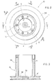
- a forced discharge device is indicated as a whole by reference number 10 and comprises a hollow body 11, generally but not necessarily cylindrical, that has an inlet opening 12 to let wastewater in and an outlet opening 13 to let wastewater out.
- a cup shaped element indicated as a whole by reference number 14 can slide axially (in a direction defined by the x axis of the body).
- a twin piston element indicated as a whole by 15 can slide axially inside and with respect to the cup-shaped element 14.
- a distributor element 16 is fixed with respect to the body 11 and more precisely is supported by a cover 18 fixed to the body 11.
- the body 11 is formed with an internal a chamber 21, in which said inlet opening 12 opens. This opening is made in the side wall of body 11.
- the body 11 also has a lower flange 22 for attachment of an outlet part 23, in which said outlet opening 13 opens.
- the body 11 also has an upper flange 24 on which said cover 18 is screwed.
- the coupling and fixing screws are not drawn but simply indicated with their axes drawn with dashed and dotted lines.
- the body 11 has an internal seat for an O-ring or sealing ring 26, whilst the part 23 itself has a seat for an abutment ring 25, thus allowing the cup-shaped shutting element 14 to seal the chamber 21 tightly.
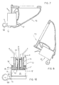
- the cup-shaped shutting element 14 has a cylindrical skirt part 28, of a suitable size and shape to be able to slide inside the chamber 21 of the body, and an upper (in fig. 1) flange part 30, extending inside from the skirt part.
- the skirt part is preferably thinner at one end 31; at the opposite end it has a seat 32 opening towards the outside for an O-ring 33, and a seat 34, facing inwards, for an O-ring 35.
- the fixed distributor element 16 comprises a cylindrical portion 36, from which a lower (in fig. 1) plate portion 38 extends; it has a circumferential peripheral seat 40 for an O-ring 41 to provide a seal against the inner surface of the cup-shaped element 14 and a through hole 39 with seats for O-rings 42, 42, for a stem of piston 15.
- the cylindrical portion of distributor 16 has a plurality of ducts for an operating fluid, said ducts being circumferentially spaced apart and referenced respectively a , b , c and d as can be seen in the plan view in Figure 2.
- the operating fluid is preferably compressed air, supplied by a compressor or a special supply system (not illustrated).
- the ducts a , b , c and d have a threaded mouthpiece for connection to said supply system, by means of solenoid valves or opening and closing devices managed by an electronic, electrical or mechanical means.
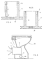
- the duct a which can also be seen in Figure 3, extends with its axis parallel to the axis of the device and ends in the vicinity of plate 38 in a radial passage towards the outside, indicated by a ', which opens into an annular chamber 45 defined between the distributor 16 and the cup-shaped element 14.
- the duct b which can also be seen in Figure 5, has a limited axial extension and opens outwards radially at the top into the annular chamber 43 through a hole b' defined between the cup-shaped element 30 and the cover 18.
- the duct c which can also be seen in Figure 1, extends in an axial direction, has a radial opening c' in a chamber 46 between the cover and the piston and an end opening c " in the outermost surface of the distributor, facing the piston 15; that is to say, the opening c" opens into a chamber 47 defined between plate 38 and piston 15.
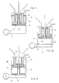
- the duct d which can also be seen in Figure 4, extends in an axial direction and has a radial opening d' at an end near the plate 38, facing towards the chamber 44 of the distributor (that is, with the device assembled, towards the chamber defined between the distributor and the piston).
- the piston 15 comprises a stem 51, a working head 52, a drive head 53 all integral with each other.
- the working head 52 slides inside the cup 14, forming a seal with O-ring 48; 49 is a stop on the cup.
- a seal is formed by the O-rings 42.
- the drive head slides along the inside wall of the distributor, a seal being formed by the upper O-ring 54 accommodated in the head 53.
- An axial duct for compressed air is defined inside the stem 51 and this duct is indicated as a whole by the letter e .
- a check valve 56 is situated on the bottom of the duct and indicated schematically by a spring-loaded ball.
- the forced discharge device is mounted downstream of the bowl of a sanitary fixture as can be seen in Figure 6 or in Figures 7 and 8.
- the sanitary fixture is indicated with the reference number 60 and is of a traditional type.
- the device 10 is mounted with the longitudinal axis x lying horizontally, with the opening 12 at the outlet of the bowl and the opening 13 connected to a per se known rotary exhaust valve 58 which will therefore not be described in detail.
- the sanitary fixture of Figures 7 and 8 is a tip-up foldaway fixture, which is shown in the position of use in Figure 7.
- the device 10 is mounted with the x axis vertical and the opening 12 at the opening of the bowl of the sanitary fixture 70.
- the device 10 is shown tipped with the sanitary fixture in the resting position.
- a vacuum is created in the chamber 21.
- Compressed air is then introduced through the duct a of the distributor and the opening a ' between the plate part 38 of the distributor and the flange 30 of the cup (Fig. 10).
- the distributor At the end of its stroke, the distributor is therefore in the position shown in Figure 11, with the cup-shaped shutting element completely retracted so as to free the opening 12.
- the wastewater can fill the chamber 21.
- Compressed air is then introduced through the duct b at the same time allowing air to evacuate through the duct a .
- the cup-shaped element 14 is thus again pushed into the extended position in Fig. 12, shutting the inlet opening 12 and preventing any return of wastewater or odors through the sanitary fixture.
- Compressed air may be introduced through the duct e at this stage to facilitate evacuation of the wastewater.
- the cycle is ended, and in any case can be repeated, on the basis of a programmable logic, until the wastewater has been completely evacuated.
Landscapes
- Engineering & Computer Science (AREA)
- Health & Medical Sciences (AREA)
- Life Sciences & Earth Sciences (AREA)
- Hydrology & Water Resources (AREA)
- Public Health (AREA)
- Water Supply & Treatment (AREA)
- Aviation & Aerospace Engineering (AREA)
- Respiratory Apparatuses And Protective Means (AREA)
- Portable Nailing Machines And Staplers (AREA)
- Vehicle Waterproofing, Decoration, And Sanitation Devices (AREA)
- Nozzles (AREA)
- Apparatus For Radiation Diagnosis (AREA)
- Containers And Packaging Bodies Having A Special Means To Remove Contents (AREA)
- Toys (AREA)
- Compressor (AREA)
- Self-Closing Valves And Venting Or Aerating Valves (AREA)
Claims (9)
- Dispositif d'évacuation forcée pour installations sanitaires comprenant un corps (11) formant une chambre interne (21), une ouverture d'entrée (12) et une ouverture de sortie (13), un élément d'obturation (14) en forme de coupelle, creux et mobile dans le sens axial dans ladite chambre, entre une position étendue dans laquelle, il ferme ladite ouverture d'entrée en l'obstruant et une position rétractée dans laquelle, il laisse libre au moins en partie ladite ouverture d'entrée, un élément à piston (15) comprenant une tige (51), une tête de travail (52), une tête de commande (53) intégral l'une à l'autre, ledit élément à piston étant mobile dans le sens axial par rapport audit élément d'obturation en forme de coupelle (14)
caractérisé par le fait qu'il comprend égalementun élément de distribution (16) fixé par rapport au corps (11) et comprenant une partie à plaque (38) placée entre ladite tête de travail et ladite tête de commande de l'élément à piston, ledit élément de distribution (16) étant engagé de façon hermétique avec ledit élément d'obturation (14) et ledit élément à piston (15) et définissant une chambre annulaire (45) avec ledit élément d'obturation (14), une chambre de distribution (44) avec l'élément à piston (15), une autre chambre annulaire (47) avec l'élément à piston et une autre chambre (43) avec l'élément d'obturation (14) comprenant également une série de conduits (a, b, c, d) pour un fluide de commande dans ledit élément de distribution (16), ledit fluide de commande étant prévu pour faire coulisser ledit élément d'obturation (14) entre une position étendue et une position rétractée et pour faire coulisser ledit élément à piston (15) entre une position étendue et une position rétractée. - Dispositif selon la revendication 1, caractérisé par le fait qu'il comprend un autre conduit (e) pour un fluide d'évacuation dans la tige du piston, ledit autre conduit ayant une ouverture sur la chambre (21).
- Dispositif selon la revendication 2, où ledit autre conduit (e) comprend une vanne de contrôle (56).
- Dispositif selon la revendication 1, où ledit distributeur est fixé au couvercle (18).
- Dispositif selon la revendication 1, caractérisé par le fait que lesdits conduits pour un fluide de commande ou de travail comprennent :un premier conduit (a) s'étendant entre une extrémité de conduit et ladite chambre annulaire (45) pour alimenter le fluide de commande pour placer ledit élément en forme de coupelle (14) dans sa position rétractéeun deuxième conduit (b) s'étendant entre une extrémité de conduit et ladite autre chambre (43) pour alimenter le fluide de commande pour placer l'élément en forme de coupelle (14) dans sa position étendueun troisième conduit (c) s'étendant entre une extrémité de conduit et ladite autre chambre (47) pour alimenter le fluide de commande pour placer ledit élément à piston dans la position étendueun quatrième conduit (d) s'étendant entre une extrémité de conduit et ladite chambre de distribution (44) pour alimenter le fluide de commande pour placer l'élément à piston dans la position rétractée.
- Dispositif selon la revendication 1, où le fluide de commande est de l'air comprimé.
- Dispositif selon la revendication 1, pouvant être monté sur des installations sanitaires fixes ou des équipements abattables et escamotables.
- Dispositif selon la revendication 1, où ledit conduit (a) a une ouverture radiale (a') à proximité de la partie à plaque du distributeur (38) pour agir sur une face de l'élément en forme de coupelle qui est une partie de la chambre annulaire (45) ledit conduit (b) a une ouverture (b') dans une position proche du couvercle (18) ledit conduit (c) a des ouvertures (c', c") pour agir sur des faces des têtes du piston (52, 53) ledit conduit (d) a une ouverture (d') à proximité de la plaque du distributeur et tournée vers la tige du piston (51) pour agir sur une face de la tête du piston (53) qui est une partie de la chambre (44).
- Dispositif selon la revendication 5, caractérisé par le fait que l'évacuation est créée dans la chambre interne (21) du corps quand ledit élément à piston est déplacé dans sa position rétractée ; l'élément en forme de coupelle (14) est dans sa position étendue où il obstrue l'ouverture d'entrée (12) et la vanne d'écoulement rotative (58) reliée à l'ouverture (13) est fermée.
Applications Claiming Priority (2)
| Application Number | Priority Date | Filing Date | Title |
|---|---|---|---|
| IT96PG000013A IT1295231B1 (it) | 1996-05-08 | 1996-05-08 | Sistema di scarico forzato di preferenza per wc e simili, funzionante ad aria compressa, adatto anche ai sanitari girevoli a scomparsa |
| ITPG960013 | 1996-05-08 |
Publications (3)
| Publication Number | Publication Date |
|---|---|
| EP0806527A2 EP0806527A2 (fr) | 1997-11-12 |
| EP0806527A3 EP0806527A3 (fr) | 1998-08-12 |
| EP0806527B1 true EP0806527B1 (fr) | 2002-09-18 |
Family
ID=11393418
Family Applications (1)
| Application Number | Title | Priority Date | Filing Date |
|---|---|---|---|
| EP97106779A Expired - Lifetime EP0806527B1 (fr) | 1996-05-08 | 1997-04-24 | Un dispositif d'évacuation actionné par air comprimé pour appareil sanitaire |
Country Status (5)
| Country | Link |
|---|---|
| EP (1) | EP0806527B1 (fr) |
| AT (1) | ATE224486T1 (fr) |
| DE (1) | DE69715507T2 (fr) |
| ES (1) | ES2184001T3 (fr) |
| IT (1) | IT1295231B1 (fr) |
Families Citing this family (2)
| Publication number | Priority date | Publication date | Assignee | Title |
|---|---|---|---|---|
| DE20000515U1 (de) * | 2000-01-14 | 2000-05-04 | Sanivac Vakuumtechnik GmbH, 22880 Wedel | Zwischenbehälter für Vakuumtoilette |
| WO2002059432A1 (fr) | 2001-01-26 | 2002-08-01 | Geberit Technik Ag | Systeme de toilettes dote d'une cuvette de toilettes |
Family Cites Families (2)
| Publication number | Priority date | Publication date | Assignee | Title |
|---|---|---|---|---|
| FR1566133A (fr) * | 1968-05-29 | 1969-05-02 | ||
| FI55550C (fi) * | 1973-12-29 | 1979-08-10 | Waertsilae Oy Ab | Vakuumavloppssystem |
-
1996
- 1996-05-08 IT IT96PG000013A patent/IT1295231B1/it active IP Right Grant
-
1997
- 1997-04-24 ES ES97106779T patent/ES2184001T3/es not_active Expired - Lifetime
- 1997-04-24 EP EP97106779A patent/EP0806527B1/fr not_active Expired - Lifetime
- 1997-04-24 DE DE69715507T patent/DE69715507T2/de not_active Expired - Fee Related
- 1997-04-24 AT AT97106779T patent/ATE224486T1/de not_active IP Right Cessation
Also Published As
| Publication number | Publication date |
|---|---|
| IT1295231B1 (it) | 1999-05-04 |
| DE69715507D1 (de) | 2002-10-24 |
| DE69715507T2 (de) | 2003-05-22 |
| ATE224486T1 (de) | 2002-10-15 |
| EP0806527A3 (fr) | 1998-08-12 |
| ITPG960013A1 (it) | 1997-11-08 |
| ES2184001T3 (es) | 2003-04-01 |
| EP0806527A2 (fr) | 1997-11-12 |
Similar Documents
| Publication | Publication Date | Title |
|---|---|---|
| KR100327630B1 (ko) | 이동식진공변기시스템 | |
| US4125124A (en) | Sequencing valve | |
| CA2148235C (fr) | Toilette a aspiration et robinet de refoulement connexe | |
| US4499921A (en) | Three-way air valve | |
| CA2484022A1 (fr) | Siege de soupape pour robinet de chasse a piston | |
| JP2012087936A (ja) | 高圧空気パルスを制御するための弁 | |
| SK164697A3 (en) | Method of controlling the function of a centrifugal pump and vacuum pump combination, and a gas-separating centrifugal pump | |
| EP0806527B1 (fr) | Un dispositif d'évacuation actionné par air comprimé pour appareil sanitaire | |
| US4951702A (en) | Bidet valve | |
| US5038814A (en) | Back flow preventer and integral vacuum breaker | |
| US6171495B1 (en) | Automatic three-way valve | |
| JPH07269739A (ja) | 弁組立体 | |
| JP4307117B2 (ja) | 管路の空気抜き装置 | |
| JPH0560253A (ja) | スピードコントローラ | |
| US20030150516A1 (en) | Arrangement in connection with circulation lubrication system | |
| JPH0668355B2 (ja) | バルブ付スチームトラップ | |
| JPS5830151Y2 (ja) | 給油ポンプの吐出部の構造 | |
| CN104007446B (zh) | 一种共形结构气路防回流吹扫装置 | |
| JP2022128877A (ja) | 弁装置の弁体作動機構 | |
| KR200303275Y1 (ko) | 수도전용 밸브 | |
| JP2884033B2 (ja) | 真空弁マス内仕切弁 | |
| CN111470552A (zh) | 一种可进行水污染处理的环保设备 | |
| KR0136788Y1 (ko) | 공기구동펌프 | |
| JPS58113677A (ja) | 湯水混合栓 | |
| JP2001141087A (ja) | フラシュバルブ |
Legal Events
| Date | Code | Title | Description |
|---|---|---|---|
| PUAI | Public reference made under article 153(3) epc to a published international application that has entered the european phase |
Free format text: ORIGINAL CODE: 0009012 |
|
| AK | Designated contracting states |
Kind code of ref document: A2 Designated state(s): AT BE CH DE ES FR GB IT LI LU NL |
|
| AX | Request for extension of the european patent |
Free format text: AL;LT;LV;SI |
|
| PUAL | Search report despatched |
Free format text: ORIGINAL CODE: 0009013 |
|
| AK | Designated contracting states |
Kind code of ref document: A3 Designated state(s): AT BE CH DE ES FR GB IT LI LU NL |
|
| 17P | Request for examination filed |
Effective date: 19990122 |
|
| RAP1 | Party data changed (applicant data changed or rights of an application transferred) |
Owner name: SANYGEN S.R.L. |
|
| ITCL | It: translation for ep claims filed |
Representative=s name: DR. ING. A. RACHELI & C. |
|
| RAP1 | Party data changed (applicant data changed or rights of an application transferred) |
Owner name: TECNOLOGIE FERROVIARIE S.R.L. |
|
| 17Q | First examination report despatched |
Effective date: 20010220 |
|
| GRAG | Despatch of communication of intention to grant |
Free format text: ORIGINAL CODE: EPIDOS AGRA |
|
| GRAG | Despatch of communication of intention to grant |
Free format text: ORIGINAL CODE: EPIDOS AGRA |
|
| RAP1 | Party data changed (applicant data changed or rights of an application transferred) |
Owner name: PRODUCTION S.R.L. |
|
| GRAG | Despatch of communication of intention to grant |
Free format text: ORIGINAL CODE: EPIDOS AGRA |
|
| GRAH | Despatch of communication of intention to grant a patent |
Free format text: ORIGINAL CODE: EPIDOS IGRA |
|
| GRAH | Despatch of communication of intention to grant a patent |
Free format text: ORIGINAL CODE: EPIDOS IGRA |
|
| GRAA | (expected) grant |
Free format text: ORIGINAL CODE: 0009210 |
|
| AK | Designated contracting states |
Kind code of ref document: B1 Designated state(s): AT BE CH DE ES FR GB IT LI LU NL |
|
| PG25 | Lapsed in a contracting state [announced via postgrant information from national office to epo] |
Ref country code: NL Free format text: LAPSE BECAUSE OF FAILURE TO SUBMIT A TRANSLATION OF THE DESCRIPTION OR TO PAY THE FEE WITHIN THE PRESCRIBED TIME-LIMIT Effective date: 20020918 Ref country code: LI Free format text: LAPSE BECAUSE OF FAILURE TO SUBMIT A TRANSLATION OF THE DESCRIPTION OR TO PAY THE FEE WITHIN THE PRESCRIBED TIME-LIMIT Effective date: 20020918 Ref country code: FR Free format text: LAPSE BECAUSE OF NON-PAYMENT OF DUE FEES Effective date: 20020918 Ref country code: CH Free format text: LAPSE BECAUSE OF FAILURE TO SUBMIT A TRANSLATION OF THE DESCRIPTION OR TO PAY THE FEE WITHIN THE PRESCRIBED TIME-LIMIT Effective date: 20020918 Ref country code: BE Free format text: LAPSE BECAUSE OF FAILURE TO SUBMIT A TRANSLATION OF THE DESCRIPTION OR TO PAY THE FEE WITHIN THE PRESCRIBED TIME-LIMIT Effective date: 20020918 Ref country code: AT Free format text: LAPSE BECAUSE OF FAILURE TO SUBMIT A TRANSLATION OF THE DESCRIPTION OR TO PAY THE FEE WITHIN THE PRESCRIBED TIME-LIMIT Effective date: 20020918 |
|
| REF | Corresponds to: |
Ref document number: 224486 Country of ref document: AT Date of ref document: 20021015 Kind code of ref document: T |
|
| REG | Reference to a national code |
Ref country code: GB Ref legal event code: FG4D |
|
| REG | Reference to a national code |
Ref country code: CH Ref legal event code: EP |
|
| REF | Corresponds to: |
Ref document number: 69715507 Country of ref document: DE Date of ref document: 20021024 |
|
| RAP2 | Party data changed (patent owner data changed or rights of a patent transferred) |
Owner name: PRODUCTION S.P.A. |
|
| NLV1 | Nl: lapsed or annulled due to failure to fulfill the requirements of art. 29p and 29m of the patents act | ||
| REG | Reference to a national code |
Ref country code: ES Ref legal event code: FG2A Ref document number: 2184001 Country of ref document: ES Kind code of ref document: T3 |
|
| REG | Reference to a national code |
Ref country code: CH Ref legal event code: PL |
|
| PG25 | Lapsed in a contracting state [announced via postgrant information from national office to epo] |
Ref country code: LU Free format text: LAPSE BECAUSE OF NON-PAYMENT OF DUE FEES Effective date: 20030424 Ref country code: GB Free format text: LAPSE BECAUSE OF NON-PAYMENT OF DUE FEES Effective date: 20030424 |
|
| EN | Fr: translation not filed | ||
| PLBE | No opposition filed within time limit |
Free format text: ORIGINAL CODE: 0009261 |
|
| STAA | Information on the status of an ep patent application or granted ep patent |
Free format text: STATUS: NO OPPOSITION FILED WITHIN TIME LIMIT |
|
| 26N | No opposition filed |
Effective date: 20030619 |
|
| GBPC | Gb: european patent ceased through non-payment of renewal fee | ||
| PGFP | Annual fee paid to national office [announced via postgrant information from national office to epo] |
Ref country code: IT Payment date: 20060430 Year of fee payment: 10 |
|
| PGFP | Annual fee paid to national office [announced via postgrant information from national office to epo] |
Ref country code: ES Payment date: 20070508 Year of fee payment: 11 Ref country code: DE Payment date: 20070508 Year of fee payment: 11 |
|
| PG25 | Lapsed in a contracting state [announced via postgrant information from national office to epo] |
Ref country code: DE Free format text: LAPSE BECAUSE OF NON-PAYMENT OF DUE FEES Effective date: 20081101 |
|
| REG | Reference to a national code |
Ref country code: ES Ref legal event code: FD2A Effective date: 20080425 |
|
| PG25 | Lapsed in a contracting state [announced via postgrant information from national office to epo] |
Ref country code: ES Free format text: LAPSE BECAUSE OF NON-PAYMENT OF DUE FEES Effective date: 20080425 |
|
| PG25 | Lapsed in a contracting state [announced via postgrant information from national office to epo] |
Ref country code: IT Free format text: LAPSE BECAUSE OF NON-PAYMENT OF DUE FEES Effective date: 20070424 |