EP0806378A2 - Unité de réglage de position, spécialement dans des machines d'emballage - Google Patents
Unité de réglage de position, spécialement dans des machines d'emballage Download PDFInfo
- Publication number
- EP0806378A2 EP0806378A2 EP96120127A EP96120127A EP0806378A2 EP 0806378 A2 EP0806378 A2 EP 0806378A2 EP 96120127 A EP96120127 A EP 96120127A EP 96120127 A EP96120127 A EP 96120127A EP 0806378 A2 EP0806378 A2 EP 0806378A2
- Authority
- EP
- European Patent Office
- Prior art keywords
- spindles
- spindle
- unit according
- adjusting unit
- guide pieces
- Prior art date
- Legal status (The legal status is an assumption and is not a legal conclusion. Google has not performed a legal analysis and makes no representation as to the accuracy of the status listed.)
- Granted
Links
- 238000004806 packaging method and process Methods 0.000 title claims description 5
- 230000005540 biological transmission Effects 0.000 claims abstract description 14
- 210000003746 feather Anatomy 0.000 claims description 5
- 238000011144 upstream manufacturing Methods 0.000 claims description 2
- 239000011295 pitch Substances 0.000 description 3
- 238000006073 displacement reaction Methods 0.000 description 1
- 238000005461 lubrication Methods 0.000 description 1
- 238000012858 packaging process Methods 0.000 description 1
Images

Classifications
-
- B—PERFORMING OPERATIONS; TRANSPORTING
- B65—CONVEYING; PACKING; STORING; HANDLING THIN OR FILAMENTARY MATERIAL
- B65G—TRANSPORT OR STORAGE DEVICES, e.g. CONVEYORS FOR LOADING OR TIPPING, SHOP CONVEYOR SYSTEMS OR PNEUMATIC TUBE CONVEYORS
- B65G21/00—Supporting or protective framework or housings for endless load-carriers or traction elements of belt or chain conveyors
- B65G21/20—Means incorporated in, or attached to, framework or housings for guiding load-carriers, traction elements or loads supported on moving surfaces
- B65G21/2045—Mechanical means for guiding or retaining the load on the load-carrying surface
- B65G21/2063—Mechanical means for guiding or retaining the load on the load-carrying surface comprising elements not movable in the direction of load-transport
- B65G21/2072—Laterial guidance means
-
- B—PERFORMING OPERATIONS; TRANSPORTING
- B65—CONVEYING; PACKING; STORING; HANDLING THIN OR FILAMENTARY MATERIAL
- B65B—MACHINES, APPARATUS OR DEVICES FOR, OR METHODS OF, PACKAGING ARTICLES OR MATERIALS; UNPACKING
- B65B59/00—Arrangements to enable machines to handle articles of different sizes, to produce packages of different sizes, to vary the contents of packages, to handle different types of packaging material, or to give access for cleaning or maintenance purposes
- B65B59/001—Arrangements to enable adjustments related to the product to be packaged
-
- B—PERFORMING OPERATIONS; TRANSPORTING
- B65—CONVEYING; PACKING; STORING; HANDLING THIN OR FILAMENTARY MATERIAL
- B65B—MACHINES, APPARATUS OR DEVICES FOR, OR METHODS OF, PACKAGING ARTICLES OR MATERIALS; UNPACKING
- B65B59/00—Arrangements to enable machines to handle articles of different sizes, to produce packages of different sizes, to vary the contents of packages, to handle different types of packaging material, or to give access for cleaning or maintenance purposes
- B65B59/005—Adjustable conveying means
-
- F—MECHANICAL ENGINEERING; LIGHTING; HEATING; WEAPONS; BLASTING
- F16—ENGINEERING ELEMENTS AND UNITS; GENERAL MEASURES FOR PRODUCING AND MAINTAINING EFFECTIVE FUNCTIONING OF MACHINES OR INSTALLATIONS; THERMAL INSULATION IN GENERAL
- F16H—GEARING
- F16H25/00—Gearings comprising primarily only cams, cam-followers and screw-and-nut mechanisms
- F16H25/18—Gearings comprising primarily only cams, cam-followers and screw-and-nut mechanisms for conveying or interconverting oscillating or reciprocating motions
- F16H25/20—Screw mechanisms
-
- B—PERFORMING OPERATIONS; TRANSPORTING
- B65—CONVEYING; PACKING; STORING; HANDLING THIN OR FILAMENTARY MATERIAL
- B65G—TRANSPORT OR STORAGE DEVICES, e.g. CONVEYORS FOR LOADING OR TIPPING, SHOP CONVEYOR SYSTEMS OR PNEUMATIC TUBE CONVEYORS
- B65G2201/00—Indexing codes relating to handling devices, e.g. conveyors, characterised by the type of product or load being conveyed or handled
- B65G2201/02—Articles
- B65G2201/0235—Containers
- B65G2201/0244—Bottles
-
- F—MECHANICAL ENGINEERING; LIGHTING; HEATING; WEAPONS; BLASTING
- F16—ENGINEERING ELEMENTS AND UNITS; GENERAL MEASURES FOR PRODUCING AND MAINTAINING EFFECTIVE FUNCTIONING OF MACHINES OR INSTALLATIONS; THERMAL INSULATION IN GENERAL
- F16H—GEARING
- F16H25/00—Gearings comprising primarily only cams, cam-followers and screw-and-nut mechanisms
- F16H25/18—Gearings comprising primarily only cams, cam-followers and screw-and-nut mechanisms for conveying or interconverting oscillating or reciprocating motions
- F16H25/20—Screw mechanisms
- F16H2025/204—Axial sliding means, i.e. for rotary support and axial guiding of nut or screw shaft
Definitions
- the invention relates to an adjustment unit, in particular in packaging machines, for continuously changing the positioning of guide pieces for objects to be packaged, such as cans, bottles or the like, arranged in parallel rows, with a crossbar arranged transversely to the transport direction, on which the guide pieces are slidably mounted, in the crossmember is arranged at least one spindle which cooperates with a spindle nut which is axially displaceable in the crossmember and which is connected to the guide piece via a feather key guided in a slot provided in the crossmember.
- Adjustment units of this type are used to quickly convert the machines to other products or to products of different dimensions.
- Baffles can be arranged on the guide pieces, for example, which extend from above the transport path between the products and separate product rows from one another and lead in the rows thus formed.
- Adjustment units arranged below the transport routes are responsible, for example, for adjusting the distance between conveyor belts or chains.
- the invention is based on an adjusting device in which only a spindle is arranged in the tubular cross member, which is either provided with a continuous thread over its entire length or has a right-hand thread over half its length and a left-hand thread on the other.
- the rotation of the spindle is only transferred to one guide piece or in the second case to two guide pieces or, if several guide pieces are combined to form a guide piece group, to the respective group.
- the spindle is also designed with a right-hand and a left-hand thread.
- the distances between the guide pieces of a group always remain constant when moving. Only the distances between guide pieces of different groups change. In any case, the shift of one group means that the other group is also shifted. If the distance between the guide pieces is now to be set for setting objects of smaller dimensions, the spindle is rotated, the distance between two guide pieces being reduced, but the distance between the product rows also increasing. With such an adjustment unit, it is therefore necessary to subsequently bring the product series together again for the actual packaging process. Due to the fixed dependency of the adjustment movements of the group members assigned to each other, the possible uses and variations of such a device are severely limited.
- the disadvantage here lies in the complicated and fault-prone structure and in the dependence on the given thread pitch of the spindle and the fixed geometry of the rod.
- the invention is therefore based on the object of designing an adjustment unit of the type mentioned in such a way that proportional adjustment is also possible with a simple and compact design, but here there is a greater range of variation in the adjustment with less assembly effort.
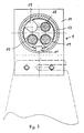
- the invention solves this problem according to claim 1 in that at least two spindles are arranged parallel to one another in the crossmember and the spindle nut (s) assigned to each spindle has a threaded bore interacting with the corresponding spindle and at least one further through-bore through which the neighboring spindle (s) is / are passed freely and the spindle movements can be decoupled from one another.
- each spindle is assigned a spindle nut which is cylindrical in shape and corresponds in diameter to the inside diameter of the crossmember, which ensures good tilt-free guidance in the tube.
- the adjacent spindles, which do not interact with this spindle nut, are freely guided through corresponding bores or recesses.
- each spindle can be equipped with its own drive, so that each guide piece can be adjusted individually.
- gears of different numbers of teeth are provided in the gearboxes, according to the invention there is still the possibility of varying the gear ratios between the drive and spindles in the gearbox, so that with constant drive individual guide pieces over a shorter distance and others over a longer distance - namely in a preselectable distance Relationship to each other - can be shifted.
- the spindles or individual spindles can have a right-hand thread on one half of their length and a left-hand thread on the other half. In this way, the distances between two guide pieces which are connected to the same spindle can be influenced.
- Such spindles can also be formed in two parts, wherein both parts of the spindles can be coupled together. This can compensate for tolerance and assembly errors.
- the central guide piece is arranged immovably, so that when the spindles are actuated, the left and right of it Adjust the fixed guide piece to adjacent guide pieces as desired.
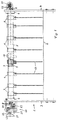
- FIG. 1 shows an adjustment unit in a packaging machine and is generally provided with reference number 1.
- the adjustment unit 1 is built in a portal-like manner over the merely indicated transport route 2.
- a carrier 3 and 4 is screwed to the machine frame, between which a tubular cross member 5 is fastened in clamping pieces 6.
- Eight guide pieces 9 and another 10 on the center of the cross member 5, which is fixed there, are slidably mounted on the cross member 5.
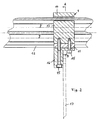
- each guide piece is connected to a spindle nut 13 within the cross member 5 via a feather key 11 which is guided in a slot guide 12 in the cross member 5.
- a tab 16 is fastened by means of screws 15, which connect the frame 14 to the feather key 11 and the spindle nut 13, to which a guide plate 17 is in turn screwed.
- the feather key 11 is in a groove on the circumference of the spindle nut 13, which is cylindrical and in the present case has a threaded bore 18 for the spindle 7 cooperating with it and three further recesses 19 through which the remaining three spindles 7 are freely guided For reasons of clarity, only two further spindles are shown).
- the drive for the spindles 7, generally designated 20, is arranged on the left support 3. It is a handwheel 21 with which a shaft 22 can be rotated, which is designed as a drive shaft that leads to a gear 23, the output shafts of which serve to rotate the spindles 7.
- the gear 20 consists of intermeshing gear wheels 24 which transmit the rotational movement of the shaft 22 to the individual spindles 7 with the same or different transmission ratio.
- the gearwheels 24 are to be moved into or out of operative connection with the spindles 7 with the aid of thrust levers 25.
- the spindles 7 are provided with a right-hand thread on one half of their length and with a left-hand thread on the other half.
- Each spindle 7 is then assigned two spindle nuts 11, by means of which a guide piece 9 can be adjusted in each case.
- the guide pieces 9 are thus coupled to one another in pairs symmetrically to the guide piece 10.
- a suitable choice of the thread pitches of the individual spindles 7 or the gear ratios in the gear 20 makes it possible to position the respective guide pieces 9 or each pair of guide pieces 9 with a wide range of variation.
- the rotational movement of the spindle (s) 7 is transmitted with the help of a bevel pinion gear 26 to a transmission shaft 27 which extends at a right angle from the adjusting unit 1.
- the transmission shaft 27 leads to an adjacent adjustment unit 1, where the rotary movement of the shaft 27 is also transmitted to the spindles located there via a bevel pinion gear.
- the rotary movement of the spindle 7 of an adjustment unit 1 can be transmitted to two transmission shafts 27 via two identical bevel pinion gears 26, which serve to drive the spindles 7 in further adjustment units arranged in front of and behind the adjustment unit 1.
- any suitable type of spindle can be used.
- Suitable bearings serve to better guide the guide pieces 9. In some cases, however, simple lubrication is sufficient.
Landscapes
- Engineering & Computer Science (AREA)
- Mechanical Engineering (AREA)
- General Engineering & Computer Science (AREA)
- Auxiliary Devices For And Details Of Packaging Control (AREA)
- Wrapping Of Specific Fragile Articles (AREA)
Applications Claiming Priority (2)
| Application Number | Priority Date | Filing Date | Title |
|---|---|---|---|
| DE19618373 | 1996-05-08 | ||
| DE19618373A DE19618373C1 (de) | 1996-05-08 | 1996-05-08 | Verstelleinheit in Verpackungsmaschinen |
Publications (3)
| Publication Number | Publication Date |
|---|---|
| EP0806378A2 true EP0806378A2 (fr) | 1997-11-12 |
| EP0806378A3 EP0806378A3 (fr) | 1998-08-19 |
| EP0806378B1 EP0806378B1 (fr) | 2000-06-28 |
Family
ID=7793632
Family Applications (1)
| Application Number | Title | Priority Date | Filing Date |
|---|---|---|---|
| EP96120127A Expired - Lifetime EP0806378B1 (fr) | 1996-05-08 | 1996-12-14 | Unité de réglage de position, spécialement dans des machines d'emballage |
Country Status (3)
| Country | Link |
|---|---|
| EP (1) | EP0806378B1 (fr) |
| DE (2) | DE19618373C1 (fr) |
| ES (1) | ES2149421T3 (fr) |
Cited By (2)
| Publication number | Priority date | Publication date | Assignee | Title |
|---|---|---|---|---|
| EP2942547A3 (fr) * | 2014-05-05 | 2016-01-06 | Mespack, S.L. | Dispositif de changement de format pour une machine de remplissage et de formage automatique de récipients flexibles horizontaux |
| EP2440482B2 (fr) † | 2009-06-11 | 2023-05-31 | Gebo Packaging Solutions France | Dispositif de reglage de largeur pour couloir(s) de convoyeur |
Families Citing this family (13)
| Publication number | Priority date | Publication date | Assignee | Title |
|---|---|---|---|---|
| ITMI981247A1 (it) * | 1998-06-03 | 1999-12-03 | Ronchipack S R L | Apparecchiatura per la regolazione della posizione relativa di sponde di guida per contenitori in macchine per la formazione di matrici di |
| EP1344730A1 (fr) * | 2002-03-11 | 2003-09-17 | BETT SISTEMI s.r.l. | Dispositif pour espacer régulièrement des éléments de guidage ou outils divers |
| EP1375393A1 (fr) * | 2002-06-18 | 2004-01-02 | BETT SISTEMI s.r.l. | Dispositif pour espacer régulièrement des éléments de guidage ou des outils |
| DE102009008279A1 (de) | 2009-02-10 | 2010-08-19 | Khs Ag | Verstelleinheit mit Vielfachspindel |
| WO2010091776A1 (fr) | 2009-02-10 | 2010-08-19 | Khs Gmbh | Dispositif de déplacement à utiliser avec un transporteur |
| DE102009025308A1 (de) | 2009-06-15 | 2010-12-16 | Khs Gmbh | Verstellvorrichtung |
| DE102011007488A1 (de) | 2011-04-15 | 2012-10-18 | Robert Bosch Gmbh | Formateinstellvorrichtung |
| DE102013101815A1 (de) * | 2013-02-25 | 2014-08-28 | Khs Gmbh | Transportvorrichtung mit justierbarer Führungsschiene |
| DE102013102202A1 (de) * | 2013-03-06 | 2014-09-11 | Krones Aktiengesellschaft | Vorrichtung zur Positionierung und/oder Ausrichtung ein oder mehrerer verstellbarer Leitkomponenten zur Führung von Artikeln in einem Transportsystem |
| DE202013104943U1 (de) * | 2013-11-05 | 2014-11-12 | Krones Ag | Zweiteilige Klemmvorrichtung, System zur Unterteilung einer Förderstrecke und Horizontalbalken |
| DE202014103761U1 (de) * | 2014-08-13 | 2015-11-16 | Krones Aktiengesellschaft | Klemmvorrichtung zur ortsfesten Fixierung eines Gassenblechs, System zur Unterteilung einer Förderstrecke und Horizontalbalken |
| FR3035608B1 (fr) * | 2015-04-30 | 2017-12-22 | Cermex Newtec | Solution de variation de l'espacement dans un dispositif d'ajustement |
| DE102017105260A1 (de) | 2017-03-13 | 2018-09-13 | Khs Gmbh | Vorrichtung zum Aufteilen von auf einer Transportvorrichtung transportierten Behältern |
Family Cites Families (6)
| Publication number | Priority date | Publication date | Assignee | Title |
|---|---|---|---|---|
| US2360910A (en) * | 1940-11-14 | 1944-10-24 | American Mach & Foundry | Single adjustment for vertically reciprocating tables |
| US3554353A (en) * | 1968-09-18 | 1971-01-12 | Emhart Corp | Adjustable lane guides |
| DE6915125U (de) * | 1969-04-15 | 1969-08-28 | Enzinger Union Werke Ag | Vorrichtung zum reihenweisen ordnen von flaschen auf einem laengsfoerderer |
| DE3425516A1 (de) * | 1984-07-11 | 1986-01-16 | Holstein Und Kappert Gmbh, 4600 Dortmund | Vorrichtung zum formatwechsel von fuehrungsblechen in verpackungsmaschinen |
| DE8812695U1 (de) * | 1988-10-10 | 1988-12-08 | Doboy Verpackungsmaschinen Gmbh, 2000 Schenefeld | Verstellvorrichtung für Packgut-Leitschienen einer Verpackungsmaschine |
| DE9210878U1 (de) * | 1992-08-18 | 1993-12-16 | Kettner GmbH, 83026 Rosenheim | Vorrichtung zum Einstellen der Breite von Gassen bei einer mehrspurigen Transporteinrichtung |
-
1996
- 1996-05-08 DE DE19618373A patent/DE19618373C1/de not_active Expired - Fee Related
- 1996-12-14 DE DE59605504T patent/DE59605504D1/de not_active Expired - Lifetime
- 1996-12-14 EP EP96120127A patent/EP0806378B1/fr not_active Expired - Lifetime
- 1996-12-14 ES ES96120127T patent/ES2149421T3/es not_active Expired - Lifetime
Non-Patent Citations (1)
| Title |
|---|
| None |
Cited By (2)
| Publication number | Priority date | Publication date | Assignee | Title |
|---|---|---|---|---|
| EP2440482B2 (fr) † | 2009-06-11 | 2023-05-31 | Gebo Packaging Solutions France | Dispositif de reglage de largeur pour couloir(s) de convoyeur |
| EP2942547A3 (fr) * | 2014-05-05 | 2016-01-06 | Mespack, S.L. | Dispositif de changement de format pour une machine de remplissage et de formage automatique de récipients flexibles horizontaux |
Also Published As
| Publication number | Publication date |
|---|---|
| ES2149421T3 (es) | 2000-11-01 |
| EP0806378A3 (fr) | 1998-08-19 |
| DE19618373C1 (de) | 1997-05-07 |
| EP0806378B1 (fr) | 2000-06-28 |
| DE59605504D1 (de) | 2000-08-03 |
Similar Documents
| Publication | Publication Date | Title |
|---|---|---|
| EP0806378B1 (fr) | Unité de réglage de position, spécialement dans des machines d'emballage | |
| DE3234981C3 (de) | Stanz-Biege-Maschine zum Bearbeiten von Draht oder Band | |
| EP3239075B1 (fr) | Dispositif de transport pour flux d'articles transportés les uns derrière les autres et procédé d'adaptation d'un dispositif de transport à différents articles larges | |
| EP0623514B1 (fr) | Dispositif de transport d'objets dans une machine d'emballage, spécialement pour boîtes pliantes | |
| DD260893A1 (de) | An- und abstellvorrichtung fuer die gummituchzylinder eines vier-zylinder-druckwerks fuer eine rollenrotations-offsetdruckmaschine | |
| WO1992017718A1 (fr) | Roue dentee a nombre de dents variable | |
| DE4114875A1 (de) | Anordnung zum umformen eines angefoerderten mehrspurigen und dicht gepackten behaelterstroms in mehrere parallele, jeweils durch einteilelemente voneinander getrennte behaelterreihen | |
| DE10307199B3 (de) | Walzgerüst zum Walzen von langgestrecktem Gut | |
| DE4393468C2 (de) | Getriebeanordung für einen zweiachsigen Extruder | |
| DE3224268C1 (de) | Maschine fuer die Bearbeitung von Kurbelwellen | |
| EP0956974B1 (fr) | Dispositif d'entrainement pour une assembleuse et brocheuse combinées à pas variable | |
| WO2015176875A1 (fr) | Poste de pliage et machine de collage de boîte pliante | |
| EP0093305A1 (fr) | Mécanisme pour effectuer une différence de vélocité angulaire entre un arbre d'entrée et un arbre de sortie | |
| DE102016113376A1 (de) | Transportvorrichtung | |
| EP0733175B1 (fr) | Transmission a courroie dentee | |
| DE29501098U1 (de) | Verstellvorrichtung für Führungsgeländer an Artikelförderern | |
| DE102015016397A1 (de) | Vorrichtung zur Zuführung stehender Flaschen zu einer Weiterbehandlungseinheit | |
| CH687537A5 (de) | Doppelseitige Ringspinnmaschine mit Spulenwechselvorrichtung. | |
| LU85568A1 (de) | Verstellbare stranggiesskokillenanordnung | |
| DE102006062201B4 (de) | Walzgerüst zum Walzen von langgestrecktem Gut | |
| DE2835024C2 (de) | Einrichtung zum Formen von Spiralnahtrohren aus Stahlband bzw. Blech | |
| DE3413166C2 (fr) | ||
| DE2630224A1 (de) | Verfahren zum montieren von streckwerken auf einer streckwerksbank | |
| CH666241A5 (de) | Foerdereinrichtung. | |
| EP3816479B1 (fr) | Vis à rouleaux planétaires pour un broche télescopique sans glissement |
Legal Events
| Date | Code | Title | Description |
|---|---|---|---|
| PUAI | Public reference made under article 153(3) epc to a published international application that has entered the european phase |
Free format text: ORIGINAL CODE: 0009012 |
|
| AK | Designated contracting states |
Kind code of ref document: A2 Designated state(s): DE ES FR GB IT NL |
|
| PUAL | Search report despatched |
Free format text: ORIGINAL CODE: 0009013 |
|
| AK | Designated contracting states |
Kind code of ref document: A3 Designated state(s): DE ES FR GB IT NL |
|
| 17P | Request for examination filed |
Effective date: 19981015 |
|
| GRAG | Despatch of communication of intention to grant |
Free format text: ORIGINAL CODE: EPIDOS AGRA |
|
| 17Q | First examination report despatched |
Effective date: 19991027 |
|
| GRAG | Despatch of communication of intention to grant |
Free format text: ORIGINAL CODE: EPIDOS AGRA |
|
| GRAH | Despatch of communication of intention to grant a patent |
Free format text: ORIGINAL CODE: EPIDOS IGRA |
|
| GRAH | Despatch of communication of intention to grant a patent |
Free format text: ORIGINAL CODE: EPIDOS IGRA |
|
| GRAA | (expected) grant |
Free format text: ORIGINAL CODE: 0009210 |
|
| ITF | It: translation for a ep patent filed | ||
| AK | Designated contracting states |
Kind code of ref document: B1 Designated state(s): DE ES FR GB IT NL |
|
| GBT | Gb: translation of ep patent filed (gb section 77(6)(a)/1977) |
Effective date: 20000628 |
|
| REF | Corresponds to: |
Ref document number: 59605504 Country of ref document: DE Date of ref document: 20000803 |
|
| ET | Fr: translation filed | ||
| REG | Reference to a national code |
Ref country code: ES Ref legal event code: FG2A Ref document number: 2149421 Country of ref document: ES Kind code of ref document: T3 |
|
| PLBE | No opposition filed within time limit |
Free format text: ORIGINAL CODE: 0009261 |
|
| STAA | Information on the status of an ep patent application or granted ep patent |
Free format text: STATUS: NO OPPOSITION FILED WITHIN TIME LIMIT |
|
| 26N | No opposition filed | ||
| REG | Reference to a national code |
Ref country code: GB Ref legal event code: IF02 |
|
| PGFP | Annual fee paid to national office [announced via postgrant information from national office to epo] |
Ref country code: ES Payment date: 20091222 Year of fee payment: 14 |
|
| PGFP | Annual fee paid to national office [announced via postgrant information from national office to epo] |
Ref country code: NL Payment date: 20091222 Year of fee payment: 14 |
|
| PGFP | Annual fee paid to national office [announced via postgrant information from national office to epo] |
Ref country code: IT Payment date: 20091223 Year of fee payment: 14 Ref country code: GB Payment date: 20091218 Year of fee payment: 14 Ref country code: FR Payment date: 20100108 Year of fee payment: 14 |
|
| PGFP | Annual fee paid to national office [announced via postgrant information from national office to epo] |
Ref country code: DE Payment date: 20091222 Year of fee payment: 14 |
|
| REG | Reference to a national code |
Ref country code: NL Ref legal event code: V1 Effective date: 20110701 |
|
| GBPC | Gb: european patent ceased through non-payment of renewal fee |
Effective date: 20101214 |
|
| REG | Reference to a national code |
Ref country code: FR Ref legal event code: ST Effective date: 20110831 |
|
| PG25 | Lapsed in a contracting state [announced via postgrant information from national office to epo] |
Ref country code: FR Free format text: LAPSE BECAUSE OF NON-PAYMENT OF DUE FEES Effective date: 20110103 |
|
| REG | Reference to a national code |
Ref country code: DE Ref legal event code: R119 Ref document number: 59605504 Country of ref document: DE Effective date: 20110701 |
|
| PG25 | Lapsed in a contracting state [announced via postgrant information from national office to epo] |
Ref country code: DE Free format text: LAPSE BECAUSE OF NON-PAYMENT OF DUE FEES Effective date: 20110701 Ref country code: GB Free format text: LAPSE BECAUSE OF NON-PAYMENT OF DUE FEES Effective date: 20101214 |
|
| PG25 | Lapsed in a contracting state [announced via postgrant information from national office to epo] |
Ref country code: NL Free format text: LAPSE BECAUSE OF NON-PAYMENT OF DUE FEES Effective date: 20110701 Ref country code: IT Free format text: LAPSE BECAUSE OF NON-PAYMENT OF DUE FEES Effective date: 20101214 |
|
| REG | Reference to a national code |
Ref country code: ES Ref legal event code: FD2A Effective date: 20120206 |
|
| PG25 | Lapsed in a contracting state [announced via postgrant information from national office to epo] |
Ref country code: ES Free format text: LAPSE BECAUSE OF NON-PAYMENT OF DUE FEES Effective date: 20101215 |