EP0806325A1 - Belt tensioner - Google Patents
Belt tensioner Download PDFInfo
- Publication number
- EP0806325A1 EP0806325A1 EP97107462A EP97107462A EP0806325A1 EP 0806325 A1 EP0806325 A1 EP 0806325A1 EP 97107462 A EP97107462 A EP 97107462A EP 97107462 A EP97107462 A EP 97107462A EP 0806325 A1 EP0806325 A1 EP 0806325A1
- Authority
- EP
- European Patent Office
- Prior art keywords
- belt tensioner
- fastening
- tube
- fastening end
- belt
- Prior art date
- Legal status (The legal status is an assumption and is not a legal conclusion. Google has not performed a legal analysis and makes no representation as to the accuracy of the status listed.)
- Granted
Links
- 244000089486 Phragmites australis subsp australis Species 0.000 description 3
- 238000004519 manufacturing process Methods 0.000 description 3
- 238000005452 bending Methods 0.000 description 1
- 230000005540 biological transmission Effects 0.000 description 1
- 230000014759 maintenance of location Effects 0.000 description 1
- 239000000463 material Substances 0.000 description 1
- 239000003380 propellant Substances 0.000 description 1
- 230000001960 triggered effect Effects 0.000 description 1
Images


Classifications
-
- B—PERFORMING OPERATIONS; TRANSPORTING
- B60—VEHICLES IN GENERAL
- B60R—VEHICLES, VEHICLE FITTINGS, OR VEHICLE PARTS, NOT OTHERWISE PROVIDED FOR
- B60R22/00—Safety belts or body harnesses in vehicles
- B60R22/34—Belt retractors, e.g. reels
- B60R22/46—Reels with means to tension the belt in an emergency by forced winding up
-
- B—PERFORMING OPERATIONS; TRANSPORTING
- B60—VEHICLES IN GENERAL
- B60R—VEHICLES, VEHICLE FITTINGS, OR VEHICLE PARTS, NOT OTHERWISE PROVIDED FOR
- B60R22/00—Safety belts or body harnesses in vehicles
- B60R22/18—Anchoring devices
- B60R22/195—Anchoring devices with means to tension the belt in an emergency, e.g. means of the through-anchor or splitted reel type
- B60R22/1954—Anchoring devices with means to tension the belt in an emergency, e.g. means of the through-anchor or splitted reel type characterised by fluid actuators, e.g. pyrotechnic gas generators
- B60R22/1955—Linear actuators
-
- B—PERFORMING OPERATIONS; TRANSPORTING
- B60—VEHICLES IN GENERAL
- B60R—VEHICLES, VEHICLE FITTINGS, OR VEHICLE PARTS, NOT OTHERWISE PROVIDED FOR
- B60R22/00—Safety belts or body harnesses in vehicles
- B60R22/18—Anchoring devices
- B60R22/195—Anchoring devices with means to tension the belt in an emergency, e.g. means of the through-anchor or splitted reel type
- B60R22/1951—Anchoring devices with means to tension the belt in an emergency, e.g. means of the through-anchor or splitted reel type characterised by arrangements in vehicle or relative to seat belt
-
- F—MECHANICAL ENGINEERING; LIGHTING; HEATING; WEAPONS; BLASTING
- F15—FLUID-PRESSURE ACTUATORS; HYDRAULICS OR PNEUMATICS IN GENERAL
- F15B—SYSTEMS ACTING BY MEANS OF FLUIDS IN GENERAL; FLUID-PRESSURE ACTUATORS, e.g. SERVOMOTORS; DETAILS OF FLUID-PRESSURE SYSTEMS, NOT OTHERWISE PROVIDED FOR
- F15B15/00—Fluid-actuated devices for displacing a member from one position to another; Gearing associated therewith
- F15B15/08—Characterised by the construction of the motor unit
- F15B15/12—Characterised by the construction of the motor unit of the oscillating-vane or curved-cylinder type
- F15B15/125—Characterised by the construction of the motor unit of the oscillating-vane or curved-cylinder type of the curved-cylinder type
-
- F—MECHANICAL ENGINEERING; LIGHTING; HEATING; WEAPONS; BLASTING
- F15—FLUID-PRESSURE ACTUATORS; HYDRAULICS OR PNEUMATICS IN GENERAL
- F15B—SYSTEMS ACTING BY MEANS OF FLUIDS IN GENERAL; FLUID-PRESSURE ACTUATORS, e.g. SERVOMOTORS; DETAILS OF FLUID-PRESSURE SYSTEMS, NOT OTHERWISE PROVIDED FOR
- F15B15/00—Fluid-actuated devices for displacing a member from one position to another; Gearing associated therewith
- F15B15/19—Pyrotechnical actuators
Definitions
- the invention relates to a belt tensioner for a seat belt, with a piston-cylinder unit.
- belt tensioners have usually been fastened to a vehicle or a vehicle seat by means of screw connections, a screw extending through a tab welded to the wall of a tube.
- an additional element attached to the tube such as a cable deflector
- flanges by means of which the belt tensioner can be fixed in position on at least one level due to the flat flange.
- tabs or flanges welded to a pipe or to an additional element for fastening the belt tensioner makes its manufacture more expensive.
- the invention provides a simply constructed belt tensioner, in which no additional part, such as a tab, has to be welded to the tube, so that the belt tensioner consists of fewer individual parts, which makes it inexpensive to manufacture.
- This is achieved according to the invention in a belt tensioner of the type mentioned at the outset in that the wall of the tube is flattened in the region of its fastening end and forms a fastening flange on which a fastening means for attaching the belt tensioner to the vehicle or to the vehicle seat can engage. Additional parts to be attached to the wall of the tube are thereby avoided without strength problems occurring since the material cross section in the cylindrical region corresponds to that in the flattened region of the tube.
- Wall sections of the tube are preferably pressed flat to form the flattened region.
- the tube is pressed flat in the region of its fastening end to form a two-layer, plate-shaped fastening flange.
- the belt tensioner can be fastened to the vehicle or the vehicle seat through at least one opening at the fastening end, in that the fastening means extends through the opening.
- the tube is at least partially curved transversely to its longitudinal direction.
- the tube can thus be better adapted to the spatial conditions in the vehicle by locking the attachment end, for example, in hard-to-reach places on the vehicle or on the vehicle seat and by bending the attachment end or additionally the remaining tube section, the belt buckle-side end to the optimal position of a connected to the piston Belt buckle is aligned.
- a belt tensioner 1 which comprises a piston-cylinder unit, which consists of a piston 3 and a tube 5.
- a traction cable 7 is attached, which connects the piston 3 to a belt buckle 9.
- a chamber with a pyrotechnic propellant for driving the piston 3 is provided at the end 11 of the tube 5 on the belt buckle side, which chamber can be triggered by an igniter 13.
- the end of the tube 5 opposite the end 11 on the belt buckle is referred to as its fastening end 15.
- the tube 5 is pressed flat at the fastening end 15 to form a two-layer, plate-shaped fastening flange, as can be seen more clearly in FIG. 2.
- a screw 19 can be inserted through an opening 17 in the fastening end 15, by means of which the belt tensioner 1 together with the belt buckle 9 is screwed onto a vehicle or a vehicle seat.
- the embodiment of the belt tensioner 1 shown in FIG. 3 differs from that in FIGS. 1 and 2 embodiment shown in that the wall sections of the tube 5 at the fastening end 15 are not compressed into a two-layer, plate-shaped mounting flange, but that only wall sections of the tube are pressed flat without these parallel wall sections formed touching each other.
- the fastening end 15 can be closed on the end face or, as shown in FIG. 3, open, so that a type of outflow opening is formed. Also in the embodiment according to Fig. 3, the fastening end 15 has an opening 17 through which the belt tensioner 1 e.g. can be screwed to the frame of a vehicle seat.
- the belt tensioner 1 can be fastened by means of a screw or a bolt and thereby pivotably to the vehicle or to the vehicle seat
- the fastening end 15 of the one shown in FIGS. 4 and 5 shown embodiments of the belt tensioner 1 two openings 17.
- the fastening end 15 is provided in both embodiments with a longitudinal gap 21 which starts from the end face 23 of the fastening end 15 and ends in a bore 25.
- the longitudinal gap 21 divides the fastening end into two sections 27 and 29, each with an opening 17, the sections 27, 29 in the embodiment shown in FIG. 5 being bent apart in the plane of the flat, so that the openings 17 are at a greater distance from one another have than in the embodiment shown in Fig. 4.
- the belt tensioner 1 shown in FIG. 6 is pivotably attached to a frame part 31 of a vehicle seat 33 by means of a screw which extends through the opening 17 in the fastening end 15.
- the tube 5 is curved transversely to its longitudinal direction, so that the belt buckle 9 can be placed optimally, even though the fastening end 15 is screwed onto the vehicle seat 33 in a location that is difficult to access, which would not have been suitable for a belt tensioner attachment in previously known belt tensioners with always cylindrical tubes.
- only part of the tube 5 can be curved in the longitudinal direction, e.g. only the fastening end 15 or the remaining, tubular, undeformed section, or the tube 5 can be curved over its entire length according to FIG. 6.
Landscapes
- Engineering & Computer Science (AREA)
- Mechanical Engineering (AREA)
- Physics & Mathematics (AREA)
- Fluid Mechanics (AREA)
- General Engineering & Computer Science (AREA)
- Chemical & Material Sciences (AREA)
- Analytical Chemistry (AREA)
- Automotive Seat Belt Assembly (AREA)
- Devices For Conveying Motion By Means Of Endless Flexible Members (AREA)
- Compositions Of Macromolecular Compounds (AREA)
- Cooling, Air Intake And Gas Exhaust, And Fuel Tank Arrangements In Propulsion Units (AREA)
- Actuator (AREA)
Abstract
Ein Gurtstraffer (1) mit einer Kolben-Zylinder-Einheit, ist dadurch gekennzeichnet, daß die Wandung des Rohres (5) der Kolben-Zylinder-Einheit im Bereich seines Befestigungsendes (15) abgeflacht ist und einen Befestigungsflansch bildet, an dem ein Befestigungsmittel zur Anbringung des Gurtstraffers (1) am Fahrzeug oder am Fahrzeugsitz (33) angreifen kann. <IMAGE>A belt tensioner (1) with a piston-cylinder unit is characterized in that the wall of the tube (5) of the piston-cylinder unit is flattened in the region of its fastening end (15) and forms a fastening flange to which a fastening means for Attachment of the belt tensioner (1) on the vehicle or on the vehicle seat (33) can attack. <IMAGE>
Description
Die Erfindung betrifft einen Gurtstraffer für einen Sicherheitsgurt, mit einer Kolben-Zylinder-Einheit.The invention relates to a belt tensioner for a seat belt, with a piston-cylinder unit.
Bislang werden Gurtstraffer an einem Fahrzeug oder einem Fahrzeugsitz üblicherweise durch Schraubverbindungen befestigt, wobei sich eine Schraube durch eine an der Wandung eines Rohres angeschweißte Lasche erstreckt. Darüber hinaus gibt es auch Gurtstraffer, bei denen ein am Rohr befestigtes Zusatzelement, wie z.B. ein Seilumlenker, mit Flanschen versehen ist, durch die der Gurtstraffer am Fahrzeug oder am Fahrzeugsitz aufgrund des ebenen Flansches in mindestens einer Ebene lagefest befestigt werden kann. Das Vorsehen von an einem Rohr oder an einem Zusatzelement angeschweißten Laschen oder Flanschen zur Befestigung des Gurtstraffers verteuert jedoch seine Herstellung.Up to now, belt tensioners have usually been fastened to a vehicle or a vehicle seat by means of screw connections, a screw extending through a tab welded to the wall of a tube. In addition, there are belt tensioners in which an additional element attached to the tube, such as a cable deflector, is provided with flanges, by means of which the belt tensioner can be fixed in position on at least one level due to the flat flange. However, the provision of tabs or flanges welded to a pipe or to an additional element for fastening the belt tensioner makes its manufacture more expensive.
Die Erfindung schafft einen einfach aufgebauten Gurtstraffer, bei dem kein zusätzliches Teil wie eine Lasche an das Rohr angeschweißt werden muß, so daß der Gurtstraffer aus weniger Einzelteilen besteht, was seine Herstellung kostengünstig macht. Dies wird bei einem Gurtstraffer der eingangs genannten Art erfindungsgemäß dadurch erreicht, daß die Wandung des Rohres im Bereich seines Befestigungsendes abgeflacht ist und einen Befestigungsflansch bildet, an dem ein Befestigungsmittel zur Anbringung des Gurtstraffers am Fahrzeug oder am Fahzeugsitz angreifen kann. Zusätzliche an der Wandung des Rohres anzubringende Teile werden dadurch vermieden, ohne daß Festigkeitsprobleme auftreten, da der Materialquerschnitt im zylindrischen Bereich dem im abgeflachten Bereich des Rohres entspricht.The invention provides a simply constructed belt tensioner, in which no additional part, such as a tab, has to be welded to the tube, so that the belt tensioner consists of fewer individual parts, which makes it inexpensive to manufacture. This is achieved according to the invention in a belt tensioner of the type mentioned at the outset in that the wall of the tube is flattened in the region of its fastening end and forms a fastening flange on which a fastening means for attaching the belt tensioner to the vehicle or to the vehicle seat can engage. Additional parts to be attached to the wall of the tube are thereby avoided without strength problems occurring since the material cross section in the cylindrical region corresponds to that in the flattened region of the tube.
Vorzugsweise sind Wandungsabschnitte des Rohres flachgepreßt, um den abgeflachten Bereich zu bilden.Wall sections of the tube are preferably pressed flat to form the flattened region.
Gemäß einer Ausführungsform ist das Rohr im Bereich seines Befestigungsendes zu einem zweilagigen, plattenförmigen Befestigungsflansch flachgepreßt. Durch zumindest eine Öffnung am Befestigungsende kann der Gurtstraffer am Fahrzeug oder am Fahrzeugsitz befestigt sein, indem sich das Befestigungsmittel durch die Öffnung erstreckt.According to one embodiment, the tube is pressed flat in the region of its fastening end to form a two-layer, plate-shaped fastening flange. The belt tensioner can be fastened to the vehicle or the vehicle seat through at least one opening at the fastening end, in that the fastening means extends through the opening.
Bei einer weiteren vorteilhaften Ausgestaltung ist vorgesehen, daß das Rohr quer zu seiner Längsrichtung zumindest teilweise gekrümmt ist. Das Rohr kann damit den räumlichen Gegebenheiten im Fahrzeug besser angepaßt werden, indem das Befestigungsende z.B. an schwer zugänglichen Stellen am Fahrzeug oder am Fahrzeugsitz arretiert und durch Biegung des Befestigungsendes oder zusätzlich auch des übrigen Rohrabschnitts das gurtschloßseitige Ende auf die optimale Lage eines mit dem Kolben verbundenen Gurtschlosses ausgerichtet wird.In a further advantageous embodiment it is provided that the tube is at least partially curved transversely to its longitudinal direction. The tube can thus be better adapted to the spatial conditions in the vehicle by locking the attachment end, for example, in hard-to-reach places on the vehicle or on the vehicle seat and by bending the attachment end or additionally the remaining tube section, the belt buckle-side end to the optimal position of a connected to the piston Belt buckle is aligned.
Weitere Merkmale und Vorteile der Erfindung ergeben sich aus der nachfolgenden Beschreibung und aus den nachfolgenden Zeichnungen, auf die Bezug genommen wird. In den Zeichnungen zeigen:
- Fig. 1 eine Längsschnittansicht durch eine erste Ausführungsform des erfindungsgemäßen Gurtstraffers mit einem daran anschließenden Gurtschloß,
- Fig. 2 eine vergrößerte Detailansicht des Befestigungsendes des in Fig. 1 gezeigten Rohres als Teil des Gurtstraffers,
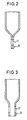
- Fig. 3 eine Längsschnittansicht durch das Befestigungsende des Rohres gemäß einer zweiten Ausführungsform,
- Fig. 4 eine Seitenansicht eines mit einem Längsspalt versehenen Befestigungsendes gemäß einer dritten Ausführungsform,
- Fig. 5 ein der in Fig. 4 gezeigten Ausführungsform weitgehend entsprechendes Befestigungsende, bei dem die durch den Längsspalt entstandenen Abschnitte seitlich auseinandergebogen sind, und
- Fig. 6 eine Vorderansicht eines Fahrzeugsitzes mit einem erfindungsgemäßen Gurtstraffer, dessen Rohr gekrümmt ist.
- 1 is a longitudinal sectional view through a first embodiment of the belt tensioner according to the invention with an adjoining belt buckle,
- 2 is an enlarged detail view of the fastening end of the tube shown in FIG. 1 as part of the belt tensioner,
- 3 shows a longitudinal sectional view through the fastening end of the tube according to a second embodiment,
- 4 shows a side view of a fastening end provided with a longitudinal gap in accordance with a third embodiment,
- 5 shows a fastening end largely corresponding to the embodiment shown in FIG. 4, in which the sections formed by the longitudinal gap are bent apart laterally, and
- Fig. 6 is a front view of a vehicle seat with a belt tensioner according to the invention, the tube is curved.
In Fig. 1 ist ein Gurtstraffer 1 gezeigt, der eine Kolben-Zylinder-Einheit umfaßt, die aus einem Kolben 3 und einem Rohr 5 besteht. Am Kolben 3 ist ein Zugseil 7 befestigt, welches den Kolben 3 mit einem Gurtschloß 9 verbindet. Am gurtschloßseitigen Ende 11 des Rohres 5 ist im Rohrinneren eine Kammer mit einem pyrotechnischen Treibsatz zum Antrieb des Kolbens 3 vorgesehen, der über einen Zünder 13 auslösbar ist. Das dem gurtschloßseitigen Ende 11 gegenüberliegende Ende des Rohres 5 wird als sein Befestigungsende 15 bezeichnet.In Fig. 1, a
Das Rohr 5 ist am Befestigungsende 15 zu einem zweilagigen, plattenförmigen Befestigungsflansch flachgepreßt, wie in Fig. 2 deutlicher zu erkennen ist. Durch eine Öffnung 17 im Befestigungsende 15 kann eine Schraube 19 gesteckt werden, mittels der der Gurtstraffer 1 samt Gurtschloß 9 an einem Fahrzeug oder einem Fahrzeugsitz festgeschraubt wird.The tube 5 is pressed flat at the fastening
Die in Fig. 3 gezeigte Ausführungsform des Gurtstraffers 1 unterscheidet sich von der in den Fign. 1 und 2 gezeigten Ausführungsform dadurch, daß die Wandungsabschnitte des Rohres 5 am Befestigungsende 15 nicht zu einem zweilagigen, plattenförmigen Befestigungsflansch zusammengepreßt sind, sondern daß nur Wandungsabschnitte des Rohres flachgepreßt sind, ohne daß sich diese entstandenen parallelen Wandungsabschnitte gegenseitig berühren. Das Befestigungsende 15 kann stirnseitig geschlossen oder, wie in Fig. 3 gezeigt, offen sein, so daß sich eine Art Ausströmöffnung bildet. Auch bei der Ausführungsform nach Fig. 3 weist das Befestigungsende 15 eine Öffnung 17 auf, über die der Gurtstraffer 1 z.B. an den Rahmen eines Fahrzeugsitzes geschraubt werden kann.The embodiment of the
Während die in den Fign. 1 und 2 gezeigten Gurtstraffer 1 mittels einer Schraube oder eines Bolzens und dadurch schwenkbar am Fahrzeug oder am Fahrzeugsitz befestigt werden können, weist das Befestigungsende 15 der in den Fign. 4 und 5 gezeigten Ausführungsformen des Gurtstraffers 1 zwei Öffnungen 17 auf. Das Befestigungsende 15 ist bei beiden Ausführungsformen mit einem Längsspalt 21 versehen, der von der Stirnseite 23 des Befestigungsendes 15 ausgeht und in einer Bohrung 25 endet. Der Längsspalt 21 teilt das Befestigungsende in zwei Abschnitte 27 und 29, mit jeweils einer Öffnung 17, wobei die Abschnitte 27, 29 in der in Fig. 5 gezeigten Ausführungsform in der Ebene der Abflachung auseinandergebogen sind, so daß die Öffnungen 17 einen größeren Abstand voneinander aufweisen als bei der in Fig. 4 gezeigten Ausführungsform.While the in Figs. 1 and 2, the
Der in Fig. 6 gezeigte Gurtstraffer 1 ist an einem Rahmenteil 31 eines Fahrzeugsitzes 33 mittels einer Schraube, die sich durch die Öffnung 17 im Befestigungsende 15 erstreckt, schwenkbar angebracht. Um im Rückhaltefall eine möglichst lineare Krafteinleitung vom Sicherheitsgurt in das Gurtschloß 9 zu erreichen, ist das Rohr 5 quer zu seiner Längsrichtung gekrümmt, so daß das Gurtschloß 9 optimal plazierbar ist, obwohl das Befestigungsende 15 an einem schwer zugänglichen Ort am Fahrzeugsitz 33 angeschraubt ist, der bei bislang bekannten Gurtstraffern mit stets zylindrischen Rohren nicht für eine Gurtstrafferbefestigung geeignet gewesen wäre. Je nach Anordnung des Gurtstraffers 1 kann nur ein Teil des Rohres 5 in Längsrichtung gekrümmt sein, z.B. lediglich das Befestigungsende 15 oder der restliche, rohrförmige, unverformte Abschnitt, oder das Rohr 5 kann entsprechend Fig. 6 auf seiner Gesamtlänge gekrümmt sein.The
Da die Wandung des Rohres 5 einstückig in das Befestigungsende 15 übergeht, ergibt sich im Rückhaltefall eine optimale Kraftweiterleitung zum Befestigungsmittel. Es entfallen damit zusätzliche für die Herstellung des Gurtstraffers bislang notwendige Einzelteile wie an die Wandung des Zylinders angeschweißte Befestigungslaschen.Since the wall of the tube 5 merges in one piece into the fastening
Claims (7)
Applications Claiming Priority (2)
| Application Number | Priority Date | Filing Date | Title |
|---|---|---|---|
| DE29608213U | 1996-05-06 | ||
| DE29608213U DE29608213U1 (en) | 1996-05-06 | 1996-05-06 | Belt tensioners for a seat belt |
Publications (2)
| Publication Number | Publication Date |
|---|---|
| EP0806325A1 true EP0806325A1 (en) | 1997-11-12 |
| EP0806325B1 EP0806325B1 (en) | 2001-04-11 |
Family
ID=8023621
Family Applications (1)
| Application Number | Title | Priority Date | Filing Date |
|---|---|---|---|
| EP97107462A Expired - Lifetime EP0806325B1 (en) | 1996-05-06 | 1997-05-06 | Belt tensioner |
Country Status (8)
| Country | Link |
|---|---|
| US (1) | US5879027A (en) |
| EP (1) | EP0806325B1 (en) |
| JP (1) | JP3140984B2 (en) |
| KR (1) | KR100257472B1 (en) |
| CN (1) | CN1166424A (en) |
| BR (1) | BR9702368A (en) |
| DE (2) | DE29608213U1 (en) |
| ES (1) | ES2110385T3 (en) |
Families Citing this family (11)
| Publication number | Priority date | Publication date | Assignee | Title |
|---|---|---|---|---|
| DE29706024U1 (en) * | 1997-04-04 | 1997-07-31 | Trw Occupant Restraint Systems Gmbh, 73551 Alfdorf | Belt tensioners for a seat belt system |
| DE29707352U1 (en) * | 1997-04-23 | 1997-08-21 | Trw Occupant Restraint Systems Gmbh, 73551 Alfdorf | Tightener for a seat belt |
| WO2002009984A1 (en) * | 2000-08-01 | 2002-02-07 | Takata Seat Belts, Inc. | Method of and an apparatus for presenting a seat belt buckle |
| US7188868B2 (en) * | 2001-08-23 | 2007-03-13 | Nhk Spring Co., Ltd. | Seat belt pretensioner |
| KR20040051731A (en) | 2002-12-11 | 2004-06-19 | 씨제이 주식회사 | Microorganism producing 5’-Xanthylic acid |
| DE10325473A1 (en) * | 2003-06-05 | 2005-01-05 | Keiper Gmbh & Co. Kg | Belt buckle device for a vehicle seat |
| CN100445138C (en) * | 2006-12-25 | 2008-12-24 | 浙江大学 | Pneumatic car seat belt |
| JP4921306B2 (en) * | 2007-10-01 | 2012-04-25 | 株式会社東海理化電機製作所 | Pretensioner cylinder structure and pretensioner manufacturing method |
| JP5201657B2 (en) * | 2007-11-29 | 2013-06-05 | テイ・エス テック株式会社 | Vehicle seat |
| DE102011008767A1 (en) | 2011-01-18 | 2012-07-19 | Wilfried Schwant | Lifting cylinder for safety belt system utilized for occupant in vehicle, has piston to compress air present in cylinder space, so that force of compressed air is introduced into wire rope that is guided through cylinder base |
| US8888137B2 (en) * | 2012-07-23 | 2014-11-18 | Ford Global Technologies, Llc | Serviceable seatbelt buckle and tensioner assembly |
Citations (4)
| Publication number | Priority date | Publication date | Assignee | Title |
|---|---|---|---|---|
| FR2104446A5 (en) * | 1970-08-17 | 1972-04-14 | Kangol Magnet Ltd | |
| DE3829975A1 (en) * | 1988-09-03 | 1989-10-05 | Daimler Benz Ag | Safety belt arrangement for vehicles |
| US5037132A (en) * | 1990-04-10 | 1991-08-06 | General Motors Corporation | Hydraulic seat belt load anchor |
| DE29607362U1 (en) * | 1996-04-23 | 1996-08-22 | Trw Occupant Restraint Systems Gmbh, 73551 Alfdorf | Seat belt system |
Family Cites Families (5)
| Publication number | Priority date | Publication date | Assignee | Title |
|---|---|---|---|---|
| FR2239870A1 (en) * | 1973-08-03 | 1975-02-28 | Poudres & Explosifs Ste Nale | |
| DE2853263A1 (en) * | 1978-12-09 | 1980-06-19 | Keiper Automobiltechnik Gmbh | ANCHORING FOR BELT LOCKS OF VEHICLE BELTS |
| DE4136623A1 (en) * | 1991-11-07 | 1993-05-13 | Trw Repa Gmbh | BELT TENSIONERS FOR VEHICLE SAFETY BELT SYSTEMS |
| US5607185A (en) * | 1993-11-26 | 1997-03-04 | Nippondenso Co., Ltd. | Belt tightener for seat belt |
| US5568940A (en) * | 1994-07-27 | 1996-10-29 | Trw Vehicle Safety Systems Inc. | Belt tightener for a vehicle safety belt system |
-
1996
- 1996-05-06 DE DE29608213U patent/DE29608213U1/en not_active Expired - Lifetime
-
1997
- 1997-05-02 KR KR1019970016959A patent/KR100257472B1/en not_active Expired - Fee Related
- 1997-05-05 CN CN97109782A patent/CN1166424A/en active Pending
- 1997-05-06 EP EP97107462A patent/EP0806325B1/en not_active Expired - Lifetime
- 1997-05-06 DE DE59703335T patent/DE59703335D1/en not_active Expired - Fee Related
- 1997-05-06 BR BR9702368A patent/BR9702368A/en not_active Application Discontinuation
- 1997-05-06 ES ES97107462T patent/ES2110385T3/en not_active Expired - Lifetime
- 1997-05-06 US US08/851,964 patent/US5879027A/en not_active Expired - Fee Related
- 1997-05-06 JP JP09115903A patent/JP3140984B2/en not_active Expired - Fee Related
Patent Citations (4)
| Publication number | Priority date | Publication date | Assignee | Title |
|---|---|---|---|---|
| FR2104446A5 (en) * | 1970-08-17 | 1972-04-14 | Kangol Magnet Ltd | |
| DE3829975A1 (en) * | 1988-09-03 | 1989-10-05 | Daimler Benz Ag | Safety belt arrangement for vehicles |
| US5037132A (en) * | 1990-04-10 | 1991-08-06 | General Motors Corporation | Hydraulic seat belt load anchor |
| DE29607362U1 (en) * | 1996-04-23 | 1996-08-22 | Trw Occupant Restraint Systems Gmbh, 73551 Alfdorf | Seat belt system |
Also Published As
| Publication number | Publication date |
|---|---|
| DE59703335D1 (en) | 2001-05-17 |
| KR970074385A (en) | 1997-12-10 |
| ES2110385T3 (en) | 2001-08-16 |
| EP0806325B1 (en) | 2001-04-11 |
| DE29608213U1 (en) | 1996-09-05 |
| JPH1044933A (en) | 1998-02-17 |
| BR9702368A (en) | 1998-09-15 |
| CN1166424A (en) | 1997-12-03 |
| ES2110385T1 (en) | 1998-02-16 |
| JP3140984B2 (en) | 2001-03-05 |
| US5879027A (en) | 1999-03-09 |
| KR100257472B1 (en) | 2000-08-01 |
Similar Documents
| Publication | Publication Date | Title |
|---|---|---|
| DE69500037T2 (en) | Device for carrying objects, in particular bicycles, on the rear of a motor vehicle | |
| DE69902550T2 (en) | LONG STRETCHED SUPPORT STRUCTURE WITH HOLLOW PROFILE CARRIER WITH A CROSS FLANGE ON BOTH END SURFACES | |
| EP1329367B1 (en) | Vehicle occupant restraint system | |
| DE102010030674A1 (en) | Roof rack for a vehicle | |
| EP0563728A1 (en) | Belt tensioning device for a vehicle safety seat belt system | |
| EP0806325A1 (en) | Belt tensioner | |
| DE2914229A1 (en) | SLIDING BEARING MOTOR VEHICLE SEAT | |
| DE1755287A1 (en) | Installation device for vehicle seat belt | |
| DE60019677T2 (en) | Adjustable mounting plate | |
| DE29904404U1 (en) | Belt tensioner system | |
| EP1213161A2 (en) | Trailer traction device | |
| EP0844153B1 (en) | Buckle retractor | |
| DE1937570C3 (en) | Height-adjustable headrest, especially for motor vehicles | |
| DE19721757C1 (en) | Fastener for attaching linings or decorative parts to bodywork of vehicle | |
| DE69204150T2 (en) | Torsion bar bearing with tension rings. | |
| DE69902294T2 (en) | BUMPER FASTENING DEVICE FOR MOTOR VEHICLES | |
| DE3301116A1 (en) | ADJUSTMENT FOR VEHICLE SEATS | |
| DE2905753C2 (en) | ||
| DE19840085C2 (en) | Fastening device for hoses | |
| DE4403980C2 (en) | Protection tube for belt tensioners | |
| DE10024337A1 (en) | Device for adjusting vehicle head restraint in dependence on seat adjustment has closed cable guided round two spaced guide rollers and with followers and operating device and locking device to also lock head restraint | |
| DE102005047272B3 (en) | Vehicle seat e.g. motor vehicle rear seat, has belt force target area and cross beam attachment area arranged offset to each other in seat transverse direction | |
| DE19546638A1 (en) | One=piece, direction changing anchorage for vehicle safety belt | |
| DE3710815C2 (en) | ||
| DE4412888A1 (en) | Support for folding bellows on articulated vehicle |
Legal Events
| Date | Code | Title | Description |
|---|---|---|---|
| PUAI | Public reference made under article 153(3) epc to a published international application that has entered the european phase |
Free format text: ORIGINAL CODE: 0009012 |
|
| AK | Designated contracting states |
Kind code of ref document: A1 Designated state(s): DE ES FR GB IT |
|
| ITCL | It: translation for ep claims filed |
Representative=s name: DR. ING. A. RACHELI & C. |
|
| GBC | Gb: translation of claims filed (gb section 78(7)/1977) | ||
| EL | Fr: translation of claims filed | ||
| REG | Reference to a national code |
Ref country code: ES Ref legal event code: BA2A Ref document number: 2110385 Country of ref document: ES Kind code of ref document: T1 |
|
| 17P | Request for examination filed |
Effective date: 19971222 |
|
| RAP1 | Party data changed (applicant data changed or rights of an application transferred) |
Owner name: TRW OCCUPANT RESTRAINT SYSTEMS GMBH & CO. KG |
|
| 17Q | First examination report despatched |
Effective date: 19990802 |
|
| GRAG | Despatch of communication of intention to grant |
Free format text: ORIGINAL CODE: EPIDOS AGRA |
|
| GRAG | Despatch of communication of intention to grant |
Free format text: ORIGINAL CODE: EPIDOS AGRA |
|
| GRAG | Despatch of communication of intention to grant |
Free format text: ORIGINAL CODE: EPIDOS AGRA |
|
| GRAH | Despatch of communication of intention to grant a patent |
Free format text: ORIGINAL CODE: EPIDOS IGRA |
|
| GRAH | Despatch of communication of intention to grant a patent |
Free format text: ORIGINAL CODE: EPIDOS IGRA |
|
| GRAA | (expected) grant |
Free format text: ORIGINAL CODE: 0009210 |
|
| AK | Designated contracting states |
Kind code of ref document: B1 Designated state(s): DE ES FR GB IT |
|
| ITF | It: translation for a ep patent filed | ||
| REF | Corresponds to: |
Ref document number: 59703335 Country of ref document: DE Date of ref document: 20010517 |
|
| GBT | Gb: translation of ep patent filed (gb section 77(6)(a)/1977) |
Effective date: 20010504 |
|
| ET | Fr: translation filed | ||
| REG | Reference to a national code |
Ref country code: ES Ref legal event code: FG2A Ref document number: 2110385 Country of ref document: ES Kind code of ref document: T3 |
|
| REG | Reference to a national code |
Ref country code: GB Ref legal event code: IF02 |
|
| PLBE | No opposition filed within time limit |
Free format text: ORIGINAL CODE: 0009261 |
|
| STAA | Information on the status of an ep patent application or granted ep patent |
Free format text: STATUS: NO OPPOSITION FILED WITHIN TIME LIMIT |
|
| 26N | No opposition filed | ||
| PGFP | Annual fee paid to national office [announced via postgrant information from national office to epo] |
Ref country code: GB Payment date: 20020404 Year of fee payment: 6 |
|
| PGFP | Annual fee paid to national office [announced via postgrant information from national office to epo] |
Ref country code: ES Payment date: 20020520 Year of fee payment: 6 |
|
| PGFP | Annual fee paid to national office [announced via postgrant information from national office to epo] |
Ref country code: FR Payment date: 20030505 Year of fee payment: 7 |
|
| PG25 | Lapsed in a contracting state [announced via postgrant information from national office to epo] |
Ref country code: GB Free format text: LAPSE BECAUSE OF NON-PAYMENT OF DUE FEES Effective date: 20030506 |
|
| PG25 | Lapsed in a contracting state [announced via postgrant information from national office to epo] |
Ref country code: ES Free format text: LAPSE BECAUSE OF NON-PAYMENT OF DUE FEES Effective date: 20030507 |
|
| GBPC | Gb: european patent ceased through non-payment of renewal fee |
Effective date: 20030506 |
|
| REG | Reference to a national code |
Ref country code: ES Ref legal event code: FD2A Effective date: 20030507 |
|
| PG25 | Lapsed in a contracting state [announced via postgrant information from national office to epo] |
Ref country code: FR Free format text: LAPSE BECAUSE OF NON-PAYMENT OF DUE FEES Effective date: 20050131 |
|
| REG | Reference to a national code |
Ref country code: FR Ref legal event code: ST |
|
| PG25 | Lapsed in a contracting state [announced via postgrant information from national office to epo] |
Ref country code: IT Free format text: LAPSE BECAUSE OF NON-PAYMENT OF DUE FEES;WARNING: LAPSES OF ITALIAN PATENTS WITH EFFECTIVE DATE BEFORE 2007 MAY HAVE OCCURRED AT ANY TIME BEFORE 2007. THE CORRECT EFFECTIVE DATE MAY BE DIFFERENT FROM THE ONE RECORDED. Effective date: 20050506 |
|
| PGFP | Annual fee paid to national office [announced via postgrant information from national office to epo] |
Ref country code: DE Payment date: 20050531 Year of fee payment: 9 |
|
| PG25 | Lapsed in a contracting state [announced via postgrant information from national office to epo] |
Ref country code: DE Free format text: LAPSE BECAUSE OF NON-PAYMENT OF DUE FEES Effective date: 20061201 |