EP0805976B1 - Electrochemical planar metal/metal oxide electrode - Google Patents
Electrochemical planar metal/metal oxide electrode Download PDFInfo
- Publication number
- EP0805976B1 EP0805976B1 EP96900408A EP96900408A EP0805976B1 EP 0805976 B1 EP0805976 B1 EP 0805976B1 EP 96900408 A EP96900408 A EP 96900408A EP 96900408 A EP96900408 A EP 96900408A EP 0805976 B1 EP0805976 B1 EP 0805976B1
- Authority
- EP
- European Patent Office
- Prior art keywords
- metal
- electrode
- electrically conductive
- metal oxide
- sensor
- Prior art date
- Legal status (The legal status is an assumption and is not a legal conclusion. Google has not performed a legal analysis and makes no representation as to the accuracy of the status listed.)
- Expired - Lifetime
Links
- 229910052751 metal Inorganic materials 0.000 title claims abstract description 116
- 239000002184 metal Substances 0.000 title claims abstract description 116
- 229910044991 metal oxide Inorganic materials 0.000 title claims abstract description 63
- 150000004706 metal oxides Chemical class 0.000 title claims abstract description 62
- 238000000034 method Methods 0.000 claims abstract description 34
- 238000010438 heat treatment Methods 0.000 claims abstract description 18
- 230000008569 process Effects 0.000 claims abstract description 9
- 229910052709 silver Inorganic materials 0.000 claims description 45
- 239000004332 silver Substances 0.000 claims description 45
- 239000000758 substrate Substances 0.000 claims description 43
- 239000000203 mixture Substances 0.000 claims description 38
- 239000004020 conductor Substances 0.000 claims description 28
- 239000012528 membrane Substances 0.000 claims description 28
- 239000002585 base Substances 0.000 claims description 25
- 239000003792 electrolyte Substances 0.000 claims description 25
- 239000000463 material Substances 0.000 claims description 23
- -1 alkali metal salts Chemical class 0.000 claims description 22
- 239000011248 coating agent Substances 0.000 claims description 20
- 238000000576 coating method Methods 0.000 claims description 20
- 150000003839 salts Chemical class 0.000 claims description 20
- KDLHZDBZIXYQEI-UHFFFAOYSA-N Palladium Chemical compound [Pd] KDLHZDBZIXYQEI-UHFFFAOYSA-N 0.000 claims description 14
- 238000001139 pH measurement Methods 0.000 claims description 14
- UIIMBOGNXHQVGW-UHFFFAOYSA-M Sodium bicarbonate Chemical group [Na+].OC([O-])=O UIIMBOGNXHQVGW-UHFFFAOYSA-M 0.000 claims description 10
- 239000010931 gold Substances 0.000 claims description 10
- PCHJSUWPFVWCPO-UHFFFAOYSA-N gold Chemical compound [Au] PCHJSUWPFVWCPO-UHFFFAOYSA-N 0.000 claims description 9
- 229910052737 gold Inorganic materials 0.000 claims description 9
- 239000007788 liquid Substances 0.000 claims description 8
- 230000007935 neutral effect Effects 0.000 claims description 6
- 229910052763 palladium Inorganic materials 0.000 claims description 6
- 229910000030 sodium bicarbonate Inorganic materials 0.000 claims description 5
- 229910052783 alkali metal Inorganic materials 0.000 claims description 4
- 229910052784 alkaline earth metal Chemical class 0.000 claims description 4
- BASFCYQUMIYNBI-UHFFFAOYSA-N platinum Chemical compound [Pt] BASFCYQUMIYNBI-UHFFFAOYSA-N 0.000 claims description 4
- 150000001340 alkali metals Chemical class 0.000 claims description 3
- 229910052741 iridium Inorganic materials 0.000 claims description 3
- GKOZUEZYRPOHIO-UHFFFAOYSA-N iridium atom Chemical compound [Ir] GKOZUEZYRPOHIO-UHFFFAOYSA-N 0.000 claims description 3
- 229910000510 noble metal Inorganic materials 0.000 claims description 3
- KJTLSVCANCCWHF-UHFFFAOYSA-N Ruthenium Chemical compound [Ru] KJTLSVCANCCWHF-UHFFFAOYSA-N 0.000 claims description 2
- ATJFFYVFTNAWJD-UHFFFAOYSA-N Tin Chemical compound [Sn] ATJFFYVFTNAWJD-UHFFFAOYSA-N 0.000 claims description 2
- 229910045601 alloy Inorganic materials 0.000 claims description 2
- 239000000956 alloy Substances 0.000 claims description 2
- 150000001450 anions Chemical class 0.000 claims description 2
- 229910052787 antimony Inorganic materials 0.000 claims description 2
- WATWJIUSRGPENY-UHFFFAOYSA-N antimony atom Chemical compound [Sb] WATWJIUSRGPENY-UHFFFAOYSA-N 0.000 claims description 2
- 229910052797 bismuth Inorganic materials 0.000 claims description 2
- JCXGWMGPZLAOME-UHFFFAOYSA-N bismuth atom Chemical compound [Bi] JCXGWMGPZLAOME-UHFFFAOYSA-N 0.000 claims description 2
- 229910052762 osmium Inorganic materials 0.000 claims description 2
- SYQBFIAQOQZEGI-UHFFFAOYSA-N osmium atom Chemical compound [Os] SYQBFIAQOQZEGI-UHFFFAOYSA-N 0.000 claims description 2
- 229910052697 platinum Inorganic materials 0.000 claims description 2
- 229910052703 rhodium Inorganic materials 0.000 claims description 2
- 239000010948 rhodium Substances 0.000 claims description 2
- MHOVAHRLVXNVSD-UHFFFAOYSA-N rhodium atom Chemical compound [Rh] MHOVAHRLVXNVSD-UHFFFAOYSA-N 0.000 claims description 2
- 229910052707 ruthenium Inorganic materials 0.000 claims description 2
- 229910052718 tin Inorganic materials 0.000 claims description 2
- CURLTUGMZLYLDI-UHFFFAOYSA-N Carbon dioxide Chemical compound O=C=O CURLTUGMZLYLDI-UHFFFAOYSA-N 0.000 description 39
- 229910002092 carbon dioxide Inorganic materials 0.000 description 38
- BQCADISMDOOEFD-UHFFFAOYSA-N Silver Chemical compound [Ag] BQCADISMDOOEFD-UHFFFAOYSA-N 0.000 description 19
- 239000011521 glass Substances 0.000 description 16
- 239000000243 solution Substances 0.000 description 9
- 238000004519 manufacturing process Methods 0.000 description 7
- QVGXLLKOCUKJST-UHFFFAOYSA-N atomic oxygen Chemical compound [O] QVGXLLKOCUKJST-UHFFFAOYSA-N 0.000 description 6
- 239000001301 oxygen Substances 0.000 description 6
- 229910052760 oxygen Inorganic materials 0.000 description 6
- BVKZGUZCCUSVTD-UHFFFAOYSA-M Bicarbonate Chemical compound OC([O-])=O BVKZGUZCCUSVTD-UHFFFAOYSA-M 0.000 description 5
- 230000000052 comparative effect Effects 0.000 description 5
- 238000005259 measurement Methods 0.000 description 5
- 230000004044 response Effects 0.000 description 5
- 229910021607 Silver chloride Inorganic materials 0.000 description 4
- 239000007789 gas Substances 0.000 description 4
- 238000007650 screen-printing Methods 0.000 description 4
- HKZLPVFGJNLROG-UHFFFAOYSA-M silver monochloride Chemical compound [Cl-].[Ag+] HKZLPVFGJNLROG-UHFFFAOYSA-M 0.000 description 4
- PNEYBMLMFCGWSK-UHFFFAOYSA-N aluminium oxide Inorganic materials [O-2].[O-2].[O-2].[Al+3].[Al+3] PNEYBMLMFCGWSK-UHFFFAOYSA-N 0.000 description 3
- 239000012530 fluid Substances 0.000 description 3
- 239000004800 polyvinyl chloride Substances 0.000 description 3
- 238000012360 testing method Methods 0.000 description 3
- ZLMJMSJWJFRBEC-UHFFFAOYSA-N Potassium Chemical compound [K] ZLMJMSJWJFRBEC-UHFFFAOYSA-N 0.000 description 2
- CDBYLPFSWZWCQE-UHFFFAOYSA-L Sodium Carbonate Chemical compound [Na+].[Na+].[O-]C([O-])=O CDBYLPFSWZWCQE-UHFFFAOYSA-L 0.000 description 2
- WYURNTSHIVDZCO-UHFFFAOYSA-N Tetrahydrofuran Chemical compound C1CCOC1 WYURNTSHIVDZCO-UHFFFAOYSA-N 0.000 description 2
- 239000011230 binding agent Substances 0.000 description 2
- 239000000919 ceramic Substances 0.000 description 2
- 229920001577 copolymer Polymers 0.000 description 2
- 238000003618 dip coating Methods 0.000 description 2
- 239000010408 film Substances 0.000 description 2
- 150000004820 halides Chemical class 0.000 description 2
- 239000002555 ionophore Substances 0.000 description 2
- 230000000236 ionophoric effect Effects 0.000 description 2
- 150000002739 metals Chemical class 0.000 description 2
- 229920000915 polyvinyl chloride Polymers 0.000 description 2
- 229910052700 potassium Inorganic materials 0.000 description 2
- 239000011591 potassium Substances 0.000 description 2
- BWHMMNNQKKPAPP-UHFFFAOYSA-L potassium carbonate Chemical compound [K+].[K+].[O-]C([O-])=O BWHMMNNQKKPAPP-UHFFFAOYSA-L 0.000 description 2
- 230000035945 sensitivity Effects 0.000 description 2
- 235000012431 wafers Nutrition 0.000 description 2
- XLYOFNOQVPJJNP-UHFFFAOYSA-N water Substances O XLYOFNOQVPJJNP-UHFFFAOYSA-N 0.000 description 2
- CFPFMAGBHTVLCZ-UHFFFAOYSA-N (4-chlorophenoxy)boronic acid Chemical compound OB(O)OC1=CC=C(Cl)C=C1 CFPFMAGBHTVLCZ-UHFFFAOYSA-N 0.000 description 1
- OYPRJOBELJOOCE-UHFFFAOYSA-N Calcium Chemical compound [Ca] OYPRJOBELJOOCE-UHFFFAOYSA-N 0.000 description 1
- DGAQECJNVWCQMB-PUAWFVPOSA-M Ilexoside XXIX Chemical compound C[C@@H]1CC[C@@]2(CC[C@@]3(C(=CC[C@H]4[C@]3(CC[C@@H]5[C@@]4(CC[C@@H](C5(C)C)OS(=O)(=O)[O-])C)C)[C@@H]2[C@]1(C)O)C)C(=O)O[C@H]6[C@@H]([C@H]([C@@H]([C@H](O6)CO)O)O)O.[Na+] DGAQECJNVWCQMB-PUAWFVPOSA-M 0.000 description 1
- WHXSMMKQMYFTQS-UHFFFAOYSA-N Lithium Chemical compound [Li] WHXSMMKQMYFTQS-UHFFFAOYSA-N 0.000 description 1
- FYYHWMGAXLPEAU-UHFFFAOYSA-N Magnesium Chemical compound [Mg] FYYHWMGAXLPEAU-UHFFFAOYSA-N 0.000 description 1
- 229920012485 Plasticized Polyvinyl chloride Polymers 0.000 description 1
- 239000004372 Polyvinyl alcohol Substances 0.000 description 1
- 239000002253 acid Substances 0.000 description 1
- NIXOWILDQLNWCW-UHFFFAOYSA-N acrylic acid group Chemical group C(C=C)(=O)O NIXOWILDQLNWCW-UHFFFAOYSA-N 0.000 description 1
- 239000007864 aqueous solution Substances 0.000 description 1
- 229910052790 beryllium Inorganic materials 0.000 description 1
- ATBAMAFKBVZNFJ-UHFFFAOYSA-N beryllium atom Chemical compound [Be] ATBAMAFKBVZNFJ-UHFFFAOYSA-N 0.000 description 1
- 239000013060 biological fluid Substances 0.000 description 1
- 239000012620 biological material Substances 0.000 description 1
- GAMFEMAXLMWCRG-UHFFFAOYSA-N bis(dimethylcarbamothioylsulfanyl)arsanyl n,n-dimethylcarbamodithioate Chemical compound CN(C)C(=S)S[As](SC(=S)N(C)C)SC(=S)N(C)C GAMFEMAXLMWCRG-UHFFFAOYSA-N 0.000 description 1
- 239000000872 buffer Substances 0.000 description 1
- 229910052791 calcium Inorganic materials 0.000 description 1
- 239000011575 calcium Substances 0.000 description 1
- 239000001569 carbon dioxide Substances 0.000 description 1
- 230000008859 change Effects 0.000 description 1
- 239000003795 chemical substances by application Substances 0.000 description 1
- 150000001805 chlorine compounds Chemical group 0.000 description 1
- 150000001875 compounds Chemical class 0.000 description 1
- 238000011109 contamination Methods 0.000 description 1
- 238000000151 deposition Methods 0.000 description 1
- 238000005516 engineering process Methods 0.000 description 1
- 239000001257 hydrogen Substances 0.000 description 1
- 229910052739 hydrogen Inorganic materials 0.000 description 1
- 125000004435 hydrogen atom Chemical class [H]* 0.000 description 1
- 230000006872 improvement Effects 0.000 description 1
- 239000012535 impurity Substances 0.000 description 1
- 239000011810 insulating material Substances 0.000 description 1
- 229910052744 lithium Inorganic materials 0.000 description 1
- 229910052749 magnesium Inorganic materials 0.000 description 1
- 239000011777 magnesium Substances 0.000 description 1
- 239000001095 magnesium carbonate Substances 0.000 description 1
- 229910000021 magnesium carbonate Inorganic materials 0.000 description 1
- ZLNQQNXFFQJAID-UHFFFAOYSA-L magnesium carbonate Chemical compound [Mg+2].[O-]C([O-])=O ZLNQQNXFFQJAID-UHFFFAOYSA-L 0.000 description 1
- 238000012986 modification Methods 0.000 description 1
- 230000004048 modification Effects 0.000 description 1
- 239000000178 monomer Substances 0.000 description 1
- 239000012811 non-conductive material Substances 0.000 description 1
- 230000003647 oxidation Effects 0.000 description 1
- 238000007254 oxidation reaction Methods 0.000 description 1
- 230000001590 oxidative effect Effects 0.000 description 1
- HBEQXAKJSGXAIQ-UHFFFAOYSA-N oxopalladium Chemical compound [Pd]=O HBEQXAKJSGXAIQ-UHFFFAOYSA-N 0.000 description 1
- 229910003445 palladium oxide Inorganic materials 0.000 description 1
- 239000004014 plasticizer Substances 0.000 description 1
- 238000007747 plating Methods 0.000 description 1
- 229920000642 polymer Polymers 0.000 description 1
- 229920002451 polyvinyl alcohol Polymers 0.000 description 1
- 229920001291 polyvinyl halide Polymers 0.000 description 1
- 239000011736 potassium bicarbonate Substances 0.000 description 1
- 229910000028 potassium bicarbonate Inorganic materials 0.000 description 1
- 229910000027 potassium carbonate Inorganic materials 0.000 description 1
- TYJJADVDDVDEDZ-UHFFFAOYSA-M potassium hydrogencarbonate Chemical compound [K+].OC([O-])=O TYJJADVDDVDEDZ-UHFFFAOYSA-M 0.000 description 1
- 239000000843 powder Substances 0.000 description 1
- 239000002243 precursor Substances 0.000 description 1
- 238000002360 preparation method Methods 0.000 description 1
- 230000009467 reduction Effects 0.000 description 1
- 230000035440 response to pH Effects 0.000 description 1
- 229910052701 rubidium Inorganic materials 0.000 description 1
- IGLNJRXAVVLDKE-UHFFFAOYSA-N rubidium atom Chemical compound [Rb] IGLNJRXAVVLDKE-UHFFFAOYSA-N 0.000 description 1
- 238000012216 screening Methods 0.000 description 1
- 239000011734 sodium Substances 0.000 description 1
- 229910052708 sodium Inorganic materials 0.000 description 1
- 229910000029 sodium carbonate Inorganic materials 0.000 description 1
- APSBXTVYXVQYAB-UHFFFAOYSA-M sodium docusate Chemical group [Na+].CCCCC(CC)COC(=O)CC(S([O-])(=O)=O)C(=O)OCC(CC)CCCC APSBXTVYXVQYAB-UHFFFAOYSA-M 0.000 description 1
- 239000007787 solid Substances 0.000 description 1
- 239000002904 solvent Substances 0.000 description 1
- YLQBMQCUIZJEEH-UHFFFAOYSA-N tetrahydrofuran Natural products C=1C=COC=1 YLQBMQCUIZJEEH-UHFFFAOYSA-N 0.000 description 1
- 239000010409 thin film Substances 0.000 description 1
- 230000009974 thixotropic effect Effects 0.000 description 1
Images


Classifications
-
- G—PHYSICS
- G01—MEASURING; TESTING
- G01N—INVESTIGATING OR ANALYSING MATERIALS BY DETERMINING THEIR CHEMICAL OR PHYSICAL PROPERTIES
- G01N27/00—Investigating or analysing materials by the use of electric, electrochemical, or magnetic means
- G01N27/26—Investigating or analysing materials by the use of electric, electrochemical, or magnetic means by investigating electrochemical variables; by using electrolysis or electrophoresis
- G01N27/28—Electrolytic cell components
- G01N27/30—Electrodes, e.g. test electrodes; Half-cells
- G01N27/333—Ion-selective electrodes or membranes
Definitions
- This invention relates to a planar metal/metal oxide active electrode that may be employed in sensors that measure pH and/or CO 2 .
- Electrochemical means for measuring the pH and CO 2 levels of liquid systems are well known.
- Glass sensors having membrane type of electrodes are commonly used as standards for pH and CO 2 measurements because glass sensors are predictable and provide good measuring capability.
- Glass sensors are fabricated as three-dimensional articles, with many serviceable parts. Thus, while demonstrating good measuring capability, these three-dimensional articles are more expensive and complex to manufacture as well as operate as compared to planar format sensors.
- Planar format sensors have been described in the literature (such as those taught by Foos et al., EP-A-0625704) and provide an alternative means to measuring pH and CO 2 levels. Planar sensors are typically smaller than glass sensors and much cheaper to manufacture as well as operate.
- the planar format of the sensors typically comprises relatively thin layers of materials which are applied to substrate bases using thick-film or thin-film techniques, including, for example, silk-screen printing.
- Planar sensors for the measurement of pH and CO 2 are more economically desirable than glass sensors, but planar sensors have been associated with performance problems.
- Limitations of planar pH sensors include, for example, drift in potential requiring frequent recalibrations; oxygen (O 2 ) interference (which can give incorrect answers due to varying levels of O 2 ) ; sensitivity to reduction or oxidation (redox) agents; and short lifetime of sensor, particularly due to contamination by sample components or impurities present in other sensor components.
- EP-A-125807 discloses a pH and CO 2 sensing device utilizing a heat decomposable precursor compound or an ink as a base component
- EP-A-433261 which relates to a solid state pH sensor having a metal/metal oxide indicator electrode and a metal/metal salt reference electrode.
- the problem noted above has been solved with the discovery of an improved active metal/metal oxide electrode, the active metal/metal oxide electrode prepared by a process comprising combining a non-hygroscopic particulate salt base component with a metal paste to form a metal paste mixture, heating the metal paste mixture in the presence of air for a time sufficient to oxidize a portion of the mixture to form said metal/metal oxide electrode.
- a planar sensor for measurement of pH comprising an electrically nonconductive substrate having applied thereto in a planar format: an electrically conductive material in at least one region adjacent to said substrate; a dielectric coating covering at least a lead portion of said region of said electrically conductive material but leaving exposed at least an electrode area and a contact area on said region of said electrically conductive material; and a metal/metal oxide electrode in said exposed electrode area, wherein said metal/metal oxide electrode is prepared by a process comprising combining a non-hygroscopic particulate salt base component with a metal paste to form a metal paste mixture, heating the metal paste mixture in the presence of air for a time sufficient to oxidize a portion of the mixture to form said metal/metal oxide electrode.
- a method for preparing a pH sensor comprising: (1) selecting an electrically nonconductive substrate; (2) adheringly applying thereto in a planar format: an electrically conductive material in at least one region adjacent to said substrate; a dielectric coating covering at least a lead portion of said electrically conductive region but leaving exposed at least an electrode area and a contact area of said electrically conductive region; and a metal/metal oxide electrode present on said exposed electrode area, wherein said metal/metal oxide electrode is prepared by a process comprising combining a non-hygroscopic particulate salt base component with a metal paste to form a metal paste mixture, heating the metal paste mixture in the presence of air for a time sufficient to oxidize a portion of the mixture to form said metal/metal oxide electrode.
- a method for measuring pH in a sample comprising contacting a liquid sample with the planar pH sensor described above and a reference, connecting said exposed contact area of said sensor with a pH sensing instrument; connecting said reference with said pH sensing instrument; providing an electrical current from said pH sensing instrument through said reference and said contact area of said sensor, and measuring a resulting electrical signal provided by said pH sensing instrument.
- a CO 2 planar sensor for the measurement of CO 2 has also been discovered, the sensor comprising an electrically nonconductive substrate having adheringly applied thereto in a planar format: (a) an electrically conductive material in at least a first and second region adjacent to said substrate; (b) a dielectric coating covering at least a lead portion of said first and second regions of said electrically conductive material but leaving exposed at least an electrode area and a contact area on said first and second regions; (c) a silver/silver halide electrode in said exposed electrode area of said first electrically conductive region; (d) a metal/metal oxide electrode in said exposed electrode area of said second electrically conductive region, said metal/ metal oxide electrode prepared by a process comprising combining a non-hygroscopic particulate salt base component with a metal paste to form a metal paste mixture, heating the metal paste mixture in the presence of air for a time sufficient to oxidize a portion of the mixture to form said metal/metal oxide electrode; (e) an internal electrolyte layer
- a method for preparing a CO 2 planar sensor comprising: (1) selecting an electrically nonconductive substrate; (2) adheringly applying thereto in a planar format: (a) an electrically conductive contact material in at least separate first and second regions; (b) a dielectric coating separating said first and second regions of said electrically conductive contact material, said dielectric coating covering at least a lead portion of said first and second regions of said electrically conductive material but leaving exposed at least an electrode area and a contact area on said first and second regions; (c) a silver/silver halide electrode in said exposed electrode area of said first electrically conductive region; (d) a metal/metal oxide electrode in said exposed electrode area of said second electrically conductive region, said metal/metal oxide electrode prepared by a process comprising combining a non-hygroscopic particulate salt base component with a metal paste to form a metal paste mixture, heating the metal paste mixture in the presence of air for a time sufficient to oxidize a portion of the mixture to
- a method for measuring CO 2 in a sample comprising: contacting a liquid sample with the CO 2 sensor described above, connecting said exposed contact area of said first and second electrically conductive regions of said sensor with a CO 2 sensing instrument, providing an electrical current from said CO 2 sensing instrument through said contact areas, measuring an electrical signal provided by said CO 2 sensing instrument.
- the invention provides an economical method of manufacturing planar pH and CO 2 sensors capable of accurate measurement of pH and CO 2 in sample fluids. Sensors that have been prepared using this electrode show a good response to pH or CO 2 while demonstrating minimal drift and O 2 interference.
- the invention is suitable for use in determining the pH and/or CO 2 of liquid samples.
- the invention is particularly useful for measuring the pH and/or CO 2 of biological fluids.
- Non-liquid samples may be prepared as liquid samples and thereafter tested, as known to those skilled in the art.
- the pH range that may be measured by the invention may vary greatly, with particular sensitivity realized for a pH measurement of from a pH of 3 to pH of 11.
- the metal paste in preparing the metal/metal oxide electrode, may be purchased or prepared by known techniques.
- the paste is of a thixotropic consistency (such the paste will flow) but is not of a thin, runny consistency.
- the appropriate consistency of the paste may be easily determined by those skilled in the art of preparing planar formatted sensors.
- the metals that may be used in the preparation of the active electrode are noble metals as described, for example, in "Metal-Metal Oxide and Metal Oxide Electrodes as pH Sensor" by S. Glab, et al, Crit. Rev. Anal. Chem. 21 , 29-47, 1989.
- Suitable metals include, but are not limited to, palladium, rhodium, ruthenium, osmium, iridium, platinum, tin, antimony, bismuth, alloys thereof, and mixtures thereof. More preferably the metal is palladium or iridium, most preferably, palladium.
- a base component is combined with the metal paste to form the metal paste mixture that goes to form the metal/metal oxide electrode.
- the base selected must be capable of generating a metal/metal oxide when the metal paste and base combination is heated.
- the base is a salt, such as, for example salts of an alkali metal (lithium, sodium, potassium, rubidium, and so on) and salts of an alkali earth metal (beryllium, magnesium, calcium, and so on).
- the salt remains in a particulate form at ambient conditions, i.e. the salt is non-hydroscopic.
- Preferred non-hydroscopic salts are represented by "MHB” and "MB", wherein M is defined as an alkali earth metal or alkali metal, H is hydrogen, and B is an anion selected from the group consisting of -CO 3 , -OH, and -HCO 3 (including, for example, Na 2 CO 3 , NaHCO 3 , K 2 CO 3 , KHCO 3 , MgCO 3 , and mixtures thereof).
- the most preferred base component is NaHCO 3 .
- the base component is most preferably a fine particulate such that when screen printing is the technique used for fabricating the planar sensor, the particulate does not exceed the mesh size of the screen (typically less than about 400 mesh size).
- the base should be used in an amount sufficient to provide an oxidizing effect when the metal paste mixture are heated in the presence of air, but not in such an excessive amount as to compromise the consistency of the paste for planar formatting.
- the base is used in an amount ranging from about 0.1 wt. % to about 50 wt. %, more preferably, in an amount ranging from 5 wt. % to 25 wt. %, and most preferably about 16 wt. %, with said weight percentages based on the total weight of the metal paste and base prior to heating.
- the metal paste and base may be combined prior to or during the planar formatting process.
- the metal paste mixture may be heated in the presence of air to produce a metal/metal oxide electrode prior to placement on an electrically nonconductive substrate.
- the metal paste and base are combined, mixed, and then applied to an electrically conductive contact material present on the nonconductive substrate and thereafter heated.
- the manner in which the metal paste mixture is applied to the electrically conductive contact material on the substrate may be any suitable technique resulting in a planar format, including stenciling, and known thin or thick film processes (such as described in J.L. Pedigo, et al., Hybrid Circuit Technology , Feb. 1992, pp. 28-31.
- silk screen printing is a preferred means to apply the metal paste mixture to the substrate.
- the thickness of the metal paste mixture may be varied.
- the substrate materials that make up the base support upon which the sensors are fabricated may be selected from any electrically non-conductive material. These materials are well-known and include, for example, ceramic, glass, refractory, and polymeric materials, and combinations thereof, and so on. Particularly preferred are alumina based substrate chips. Currently, most preferred substrates are of an alumina and glass binder combination. Groves may be fashioned in the nonconductive substrate such that layers can be specifically applied to sections on the substrate
- the electrically conductive material used in the sensors is preferably a noble metal, with gold most preferred.
- the electrically conductive material may be applied to the substrate in various ways, although most preferably the material is adhered to the substrate, typically by heating, prior to applying the dielectric coating and metal paste mixture.
- at least one region of the electrically conductive material is applied to the substrate.
- at least two separate regions of the electrically conductive material are applied to the substrate.
- a dielectric coating is present between the two regions on the CO 2 sensor thus insulating the conductive regions from each other.
- the dielectric coating (as widely commercially available) is also present on at least the lead portions of the electrically conductive regions but is not present on an exposed electrode area and an exposed contact area in each region of the conductive material.
- the metal paste mixture is applied adjacent to the electrically conductive region in at least the exposed electrode area.
- the metal paste is heated at a temperature and for a period sufficient to oxidize a portion of the metal paste mixture thus forming a metal/metal oxide electrode.
- oxygen may typically be present in the base component, oxygen does not have to be present during the heating.
- the heating occurs in the presence of oxygen (most conveniently air).
- the time and temperature of heating may be adjusted according to the type of heating source employed, the temperature employed, and the time of exposure.
- the metal paste mixture is heated for a period sufficient to provide an active electrode having an equilibrium of metal to metal oxide content, such as described in S. Glab, et al. (referenced previously herein).
- the paste is heated for a period of from about 1 min. to 30 min. (more preferably 5 min. to 15 min.) at a temperature of from about 450 °C to about 600 °C (more preferably from 525 °C to 575 °C) to oxidize a portion (but not all) of the electrode. Additionally the electrode may be reheated during the fabrication of the entire sensor if desired.
- the active metal/metal oxide electrode may be used in different types of sensors, most preferably planar pH and CO 2 sensors. Components described herein, as well as additional features, may be arranged in the planar format on non-conductive substrates in various configurations.
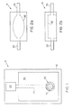
- a pH sensor 5 is present on an electrically nonconductive substrate 10 having present thereon an electrically conductive material in one region 15, 20, 25 adheringly applied adjacent to the substrate 10 .
- the insulating dielectric coating 26 is applied over the substrate and electrically conductive lead portion 20 but not over an exposed electrode area 15 and an exposed contact area 25 .
- the metal paste mixture is applied and becomes the metal/metal oxide active electrode 30 upon heating in the presence of air.
- the exposed contact area 25 is where electrical contact may be made between the sensor 5 and the pH sensing instrument.
- a sample chamber 31 may be superimposed upon the active electrode area 15, 30 of the sensor 5 so that the fluid sample enters and exits through the sample tube 33 and is confined in a sample chamber contact region 32 such that contact is made between the sample and the active electrode 30 (and reference electrode when present in the sensor chip).
- the sensor 5 may directly immersed in a fluid sample such that a sample chamber is not part of the configuration of the sensor.
- FIG. 3 shows a Severinghaus type of sensor 35 that may be used in the measurement of CO 2 .
- This sensor 35 differs from the pH sensor 5 by having an additional region of electrically conductive material 37, 38, 39 with an exposed active electrode area 39 (with no dielectric coating) having present thereon a silver/silver halide material 40 that is used as an internal reference electrode.
- the second region of electrically conductive material also has present an exposed contact area 37 and a dielectric coating 26 over a lead portion of the electrically conductive material.
- the metal/metal oxide electrode area 15, 30; lead 20; and contact area 25 are insulated from the silver/silver halide electrode 39 , lead 38 , and contact area 37 that form the internal reference electrode by the dielectric coating.
- the mV output between the metal/metal oxide electrode 30 and the silver/silver halide electrode 39 is linearly related to log pCO 2 .
- the halide of the internal reference electrode is chloride.
- the silver/silver halide electrode may be pre-formed and plated on at least the exposed electrode area of the conductive material of substrate or may be applied as a paste and thereafter heated to form the silver/silver halide electrode.
- FIG. 4 a pH sensor is shown where electrical contact between the active electrode 30 , reference electrode 50 , and sensing equipment (or instrument) 55 is made using the electrically conductive regions 15, 20, 25 of the sensor thereby resulting in a measurement of the pH.
- the pH sensor may have present a neutral carrier cover membrane 36 .
- the cover membrane functions to protect the active electrode from the outside environment and materials which degrade the performance of the sensor, such as redox centers and biological materials.
- the neutral carrier cover membrane itself is capable of sensing the concentration of the pH, where the protons do not go through during the measurement of pH but rather establish a potential across the cover membrane.
- the cover membrane may be applied to the planar sensor in various ways, including dip coating, and so on.
- Materials that may be used to prepare the cover membrane are well-known water permeable and gas permeable polymeric materials known to those skilled in the art. Particularly preferred polymeric or copolymeric materials that may be used include polyvinyl halide monomers. More preferably employed as the major component of the cover membrane is a polyvinyl chloride (more preferably a plasticized polyvinyl chloride).
- Other components that are typically included in the cover membrane are known ionophores and lipophilic salts.
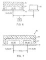
- FIG. 6 shows a sensor formatted such that an internal electrolyte 27 is superimposed over active electrode region 15, 30 and neutral carrier cover membrane 36 is superimposed over the internal electrolyte layer 27 .
- the internal electrolyte typically functions to keep the pH constant in the proximity of the electrode(s) and may be buffered if desired. Buffers that may be included are well known in the art.
- FIG. 7 shows a CO 2 Severinghaus type of sensor having present a metal/metal oxide electrode area 15, 30 and a silver/silver halide internal reference electrode area 39, 40.
- the CO 2 permeable membrane 28 is superimposed over the internal electrolyte 27.
- the CO 2 permeable membrane 28 is not permeable to acid and separates the sample from the sensor.
- the permeable membrane 28 may be applied to the sensor by various techniques including dip coating, and so on. Materials that may be used include polymeric and copolymeric materials, as well known in the art.
- the internal silver/silver halide reference electrode provides a stable reference potential.
- a bicarbonate fill solution is typically utilized as the internal electrolyte 27 prior to usage. As CO 2 from the sample diffuses through the membrane and reaches an equilibrium, the pH of the bicarbonate fill solution changes, and is detected by the sensor. The change in the pH is related to the log of the partial pressure of CO 2 .
- the metal/metal oxide component in the above-described pH and CO 2 sensors, other sensor systems may also incorporate the metal/metal oxide electrode, as may be accomplished by techniques known to those skilled in the art.
- the various components of the sensors are adheringly applied to the substrate by known techniques.
- the electrically conductive material is preferably heated on the substrate prior to applied the metal paste mixture (and silver/silver halide material).
- the silver/silver halide is preferably heated on the substrate after application to the conductive region.
- the dielectric coating may be heated/and or dried.
- the various membranes are typically dried and/or heated onto the substrate.
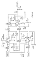
- FIG. 8 The electrical circuitry utilized for the all of the examples is shown in FIG. 8. Further description of circuitry may be found in Ion-Selective Electrode Methodology , Vol. I, Ed. Arthur K. Covington, CRC Press, 1979, pp. 32-33. Three dimensional, flow-through glass pH sensors (“Type A”) were used as standards (as available from Ciba Corning Diagnostics Corp., Medfield, MA, 278 series), as identified as sensor Type "A”. Three other types of sensors (all planar) were prepared and are identified as Types "B", "C” and D”. A silk screen printing technique was used in the fabrication of the planar sensors in the format shown in FIG. 3. As shown in FIG. 3, a metal/metal oxide and a Ag/AgCl electrode were present on the substrate chip, however, in the present set of examples, the Ag/AgCl electrode was not used, rather a Ag/AgCl external reference was used.
- the substrate chips upon which each type of planar sensors were fabricated were 5.08cm x 5.08cm (2" x 2") wafers perforated to form a total of 40 sensors.
- the wafers were made of approximately 96 % alumina and approximately 4 % glass binder, as purchased from Coors Ceramic Company, Grand Junction, Colorado.
- a gold (Au) electrically conductive region was applied to 15, 20, 25 .
- a gold strip was applied to region 37 and the upper portion of 38 .
- the lower region of 38 continuous to and including 39 had applied thereto a silver paste (obtained from Metech, Elverson PA).
- the gold was purchased from E.I. DuPont DeNemours & Company of Wilmington, Delaware.
- the chips Upon depositing the conductive regions on the substrate chips 10, the chips were heated at 850°C for 6 minutes. A dielectric insulating material 26 (Cat. No. 9615 from E.I. DuPont DeNemours & Co.) was applied over the substrate and conductive regions with the exception of an exposed first portion 15 and 25 on the first gold strip and an exposed second region 39 and 37 on the second strip. The chips were then reheated at 850 °C for 6 minutes. Thereafter, the different metal pastes, as described below, were applied to the other gold strip in the exposed electrode area. A preformed Ag/AgCl electrode plating was deposited on the exposed silver region 39 to go to form the internal reference region 40 .
- a dielectric insulating material 26 Cat. No. 9615 from E.I. DuPont DeNemours & Co.
- the metal paste was a base and metal paste mixture prepared by mixing approx. 5 g of palladium paste (purchased as Catalogue No. PC10141 from Metech Company of Elverson, PA.) and approx. 1 g of NaHCO 3 (fine powder particulate).
- the metal paste applied to the gold strip was an already formed palladium oxide paste purchased from Metech under Catalogue No. PC10119.
- the metal paste was applied to the exposed electrode area 15 of the gold strip on the substrate by silk screening and thereafter the entire chip was then heated at about 550° C for approx. 10 min. in the presence of air, thereby forming the Pd/Pd oxide active electrode.
- the Type D sensor chips differed from Type B sensors by the Type D sensors having an internal electrolyte layer adjacent to the electrodes as well as a neutral carrier cover membrane superimposed over the internal electrolyte layer, as shown in FIG. 6.
- the internal electrolyte layer was prepared as a coating using a solution formed by first dissolving approx. 2 % wt./vol. of 100 % hydrolyzed polyvinyl alcohol in 100 ml of water and thereafter adding 0.8 ml of a 0.1 M solution. of NaHCO 3 and KCl. This coating solution was then deposited over both the active electrode and the silver electrode on the chip. Thereafter, the material was dried at 80° C for about 1 hour thus forming the internal electrolyte layer on the chip.
- a cover membrane was then applied on top of the internal electrolyte membrane.
- the cover membrane was a polymer solution in 5 % wt./vol. tetrahydrofuran of 68.9 wt.% dioctyl phthlate (a plasticizer), 26.0 wt.% polyvinyl chloride (PVC), 3.1 wt.% (TDDA, ionophore for pH), 2 wt. % potassium tetra (p-chloro phenyl) borate (KTpClPB). An aliquot of this solution was spread evenly over the entire chip and the solvent allowed to evaporate to form the PVC-based cover membrane. When electrical contact was made between the Type D sensors and the sensing instrument, the cover membrane was scratched off the electrical contact area 25 prior to usage. Acrylic sample chambers, as shown and described in FIG. 2 were employed for all planar sensors used.
- This example demonstrates a linear mV response of the standard glass sensors (Type A) and two types of the planar sensors (Types B and C) when tested in aqueous solution containing bicarbonate.
- Variations in pH level were produced by varying the percent of CO 2 in solution and the concentration of bicarbonate, with the solution kept at approx. 37 °C. Carbon dioxide was used to generate the pH values.
- the O 2 levels were also varied with the CO 2 levels to test for O 2 interference. A total of three different pH conditions and levels of CO 2 gas in aqueous samples containing bicarbonate were tested.
- the output of the pH sensors was measured as the potential (volts) between the active electrode and an external reference.
- the mV output of the sensors was measured, with results summarized in TABLE I below and illustrated in FIG. 9. As shown in the figure, line a is the mV output from the glass sensors (Type A), lines b 1-3 are from the Type B planar pH sensors (INVENTION), and lines c 1-2 are from the Type C planar pH sensors (COMPARATIVE). Results indicated that all sensors provided adequate slopes and linearity to give acceptable measurement for pH.
- the amount of oxygen (O 2 ) was varied to test for drift induced by the changes in oxygen levels (i.e. O 2 interference).
- the pH and CO 2 present were kept at a constant 3% during all tests.
- a Type A glass sensor (line a) was tested as well as three Type B planar sensors (INVENTION, lines b 1-3 ) and two Type C planar sensors (COMPARATIVE, lines c 1-2 ).
- the data show little to no response changes in the output of the Type B sensors in going from 0 to 26 % O 2 (at constant 3% CO 2 ).
- the Type C sensors show undesirable drifts in the mV output induced by the changes in O 2 levels, i.e. O 2 interference.
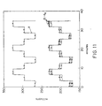
- Type D planar sensors Using the Type D planar sensors (INVENTION), samples at three different pH conditions were tested. Type A glass sensors were also tested under the same conditions to provide a standard, with the method of collecting data as described in Examples 1 and 2. Results are summarized in TABLE II and illustrated in FIG. 11. As shown, the Type D planar sensors provided comparable slopes and linearity as those provided by the standard. pH Linearity SENSOR TYPE A TYPED TYPE D TYPE D TYPE D TYPE D SLOPE -61.9 -54.6 -56.9 -56.8 -58.4 -53.5 Rsq. 0.99995 0.99986 0.99984 0.99994 0.99992 0.9998
Landscapes
- Chemical & Material Sciences (AREA)
- Life Sciences & Earth Sciences (AREA)
- Health & Medical Sciences (AREA)
- Biochemistry (AREA)
- General Physics & Mathematics (AREA)
- Electrochemistry (AREA)
- Physics & Mathematics (AREA)
- Analytical Chemistry (AREA)
- Molecular Biology (AREA)
- General Health & Medical Sciences (AREA)
- Chemical Kinetics & Catalysis (AREA)
- Immunology (AREA)
- Pathology (AREA)
- Investigating Or Analyzing Materials By The Use Of Fluid Adsorption Or Reactions (AREA)
- Electric Double-Layer Capacitors Or The Like (AREA)
- Primary Cells (AREA)
- Battery Electrode And Active Subsutance (AREA)
- Measuring Oxygen Concentration In Cells (AREA)
- Secondary Cells (AREA)
Applications Claiming Priority (3)
| Application Number | Priority Date | Filing Date | Title |
|---|---|---|---|
| US37940595A | 1995-01-27 | 1995-01-27 | |
| US379405 | 1995-01-27 | ||
| PCT/IB1996/000068 WO1996023214A1 (en) | 1995-01-27 | 1996-01-26 | Electrochemical planar metal/metal oxide electrode |
Publications (2)
| Publication Number | Publication Date |
|---|---|
| EP0805976A1 EP0805976A1 (en) | 1997-11-12 |
| EP0805976B1 true EP0805976B1 (en) | 2003-09-17 |
Family
ID=23497124
Family Applications (1)
| Application Number | Title | Priority Date | Filing Date |
|---|---|---|---|
| EP96900408A Expired - Lifetime EP0805976B1 (en) | 1995-01-27 | 1996-01-26 | Electrochemical planar metal/metal oxide electrode |
Country Status (13)
| Country | Link |
|---|---|
| US (2) | US5702575A (da) |
| EP (1) | EP0805976B1 (da) |
| JP (1) | JPH10513552A (da) |
| KR (1) | KR19980701596A (da) |
| AT (1) | ATE250223T1 (da) |
| AU (1) | AU4398796A (da) |
| BR (1) | BR9606989A (da) |
| CA (1) | CA2211536A1 (da) |
| DE (1) | DE69630016T2 (da) |
| DK (1) | DK0805976T3 (da) |
| ES (1) | ES2206555T3 (da) |
| PL (1) | PL321242A1 (da) |
| WO (1) | WO1996023214A1 (da) |
Families Citing this family (10)
| Publication number | Priority date | Publication date | Assignee | Title |
|---|---|---|---|---|
| US5554272A (en) * | 1995-08-10 | 1996-09-10 | Ciba Corning Diagnostics Corp. | Planar bicarbonate sensor |
| WO1999046586A1 (de) * | 1998-03-10 | 1999-09-16 | Micronas Gmbh | Referenzelektrode |
| KR100379792B1 (ko) * | 2000-06-12 | 2003-04-11 | 주식회사 아이센스 | 마이크로 칩형 이산화탄소 기체센서 |
| US7116547B2 (en) * | 2003-08-18 | 2006-10-03 | Wilson Greatbatch Technologies, Inc. | Use of pad printing in the manufacture of capacitors |
| US20060154416A1 (en) * | 2003-08-18 | 2006-07-13 | Seitz Keith W | Method of pad printing in the manufacture of capacitors |
| US20100148128A1 (en) * | 2005-01-18 | 2010-06-17 | Ashish Shah | Pad printing of cathode active materials for incorporation into electrochemical cells |
| KR100778237B1 (ko) * | 2006-06-26 | 2007-11-22 | 한국바이오시스템(주) | 중금속 온라인 분석시스템 |
| KR101020756B1 (ko) * | 2008-07-29 | 2011-03-09 | 한국과학기술원 | 장기 안정성을 갖는 전기화학식 이산화탄소 감지센서 |
| US10345258B2 (en) * | 2016-06-09 | 2019-07-09 | Winbond Electronics Corp. | Method for fabricating printed flexible PH sensors |
| WO2018200731A1 (en) * | 2017-04-25 | 2018-11-01 | Case Western Reserve University | Sensor for lead detection |
Family Cites Families (12)
| Publication number | Priority date | Publication date | Assignee | Title |
|---|---|---|---|---|
| US3462353A (en) * | 1963-02-25 | 1969-08-19 | Continental Oil Co | Reference electrodes of particular utility in anodic corrosion protection systems |
| US3929609A (en) * | 1973-01-31 | 1975-12-30 | Owens Illinois Inc | Method and apparatus using solid sensor electrode |
| US4052286A (en) * | 1973-01-31 | 1977-10-04 | Owens-Illinois, Inc. | Solid sensor electrode |
| US4007106A (en) * | 1973-06-22 | 1977-02-08 | Canadian Patents And Development Limited | Device for measuring oxygen concentration in molten-metal |
| US3926766A (en) * | 1974-11-01 | 1975-12-16 | Gen Electric | Miniature probe containing multifunctional electrochemical sensing electrodes |
| US4571292A (en) * | 1982-08-12 | 1986-02-18 | Case Western Reserve University | Apparatus for electrochemical measurements |
| US4536274A (en) * | 1983-04-18 | 1985-08-20 | Diamond Shamrock Chemicals Company | pH and CO2 sensing device and method of making the same |
| US4734184A (en) * | 1985-08-29 | 1988-03-29 | Diamond Sensor Systems, Inc. | Self-activating hydratable solid-state electrode apparatus |
| JPH02133599A (ja) * | 1988-11-11 | 1990-05-22 | Agency Of Ind Science & Technol | 酸化イリジウム膜の製造方法 |
| US5110441A (en) * | 1989-12-14 | 1992-05-05 | Monsanto Company | Solid state ph sensor |
| US5387329A (en) * | 1993-04-09 | 1995-02-07 | Ciba Corning Diagnostics Corp. | Extended use planar sensors |
| US5494562A (en) * | 1994-06-27 | 1996-02-27 | Ciba Corning Diagnostics Corp. | Electrochemical sensors |
-
1995
- 1995-11-01 US US08/551,596 patent/US5702575A/en not_active Expired - Lifetime
-
1996
- 1996-01-26 CA CA002211536A patent/CA2211536A1/en not_active Abandoned
- 1996-01-26 DE DE69630016T patent/DE69630016T2/de not_active Expired - Lifetime
- 1996-01-26 KR KR1019970704988A patent/KR19980701596A/ko not_active Withdrawn
- 1996-01-26 BR BR9606989A patent/BR9606989A/pt not_active Application Discontinuation
- 1996-01-26 WO PCT/IB1996/000068 patent/WO1996023214A1/en not_active Ceased
- 1996-01-26 EP EP96900408A patent/EP0805976B1/en not_active Expired - Lifetime
- 1996-01-26 ES ES96900408T patent/ES2206555T3/es not_active Expired - Lifetime
- 1996-01-26 AU AU43987/96A patent/AU4398796A/en not_active Abandoned
- 1996-01-26 AT AT96900408T patent/ATE250223T1/de not_active IP Right Cessation
- 1996-01-26 DK DK96900408T patent/DK0805976T3/da active
- 1996-01-26 JP JP8522756A patent/JPH10513552A/ja active Pending
- 1996-01-26 PL PL96321242A patent/PL321242A1/xx unknown
- 1996-08-07 US US08/693,554 patent/US5785830A/en not_active Expired - Lifetime
Also Published As
| Publication number | Publication date |
|---|---|
| EP0805976A1 (en) | 1997-11-12 |
| MX9705676A (es) | 1997-10-31 |
| US5785830A (en) | 1998-07-28 |
| US5702575A (en) | 1997-12-30 |
| JPH10513552A (ja) | 1998-12-22 |
| AU4398796A (en) | 1996-08-14 |
| CA2211536A1 (en) | 1996-08-01 |
| DE69630016D1 (de) | 2003-10-23 |
| WO1996023214A1 (en) | 1996-08-01 |
| PL321242A1 (en) | 1997-11-24 |
| KR19980701596A (ko) | 1998-05-15 |
| ES2206555T3 (es) | 2004-05-16 |
| ATE250223T1 (de) | 2003-10-15 |
| DK0805976T3 (da) | 2004-01-12 |
| BR9606989A (pt) | 1998-12-15 |
| DE69630016T2 (de) | 2004-07-08 |
Similar Documents
| Publication | Publication Date | Title |
|---|---|---|
| KR0157220B1 (ko) | 금속 산화물 전극 | |
| CA1074867A (en) | Apparatus for electrolytically determining a species in a fluid | |
| EP0551769B1 (en) | Graphite base solid state polymeric membrane ion-selective electrodes | |
| Koncki et al. | Screen-printed ruthenium dioxide electrodes for pH measurements | |
| EP1164372B1 (en) | Microchip-based differential carbon dioxide gas sensor | |
| US20050072690A1 (en) | Ion exchange membranes and dissolved gas sensors | |
| GB1584788A (en) | Ion-selective electrode | |
| EP0759551B1 (en) | Planar bicarbonate sensor | |
| EP0805976B1 (en) | Electrochemical planar metal/metal oxide electrode | |
| Bartoszewicz et al. | Calibration free solid contact electrodes with two PVC based membranes | |
| US5897758A (en) | Solid contact system for potentiometric sensors | |
| Karagounis et al. | A thick-film multiple component cathode three-electrode oxygen sensor | |
| Atkinson et al. | An investigation of the performance characteristics and operational lifetimes of multi-element thick film sensor arrays used in the determination of water quality parameters | |
| US4152233A (en) | Apparatus for electrochemical gas detection and measurement | |
| US5308468A (en) | Ion sensor | |
| JPH02297054A (ja) | ガス状または液状測定試料中のアンモニアまたはヒドラジンを測定するための電気化学的測定セル | |
| JP2001514760A (ja) | サブミニアチュアスルーホールを備えたワイアリングサブストレートの製造方法 | |
| Knoll et al. | Microfibre matrix-supported ion-selective PVC membranes | |
| Dybko et al. | Miniaturized back-side contact transducer for potentiometric sensors | |
| CA1116696A (en) | Ion-selective electrode | |
| US8758585B2 (en) | Sensor for determining gases and method for manufacturing the sensor | |
| GB2200755A (en) | Electrochemical gas sensor | |
| JP2000028573A (ja) | 炭化水素ガスセンサ | |
| MXPA97005676A (en) | Metal electrochemical electrode / oxide from me | |
| CA1093641A (en) | Ion-selective electrode |
Legal Events
| Date | Code | Title | Description |
|---|---|---|---|
| PUAI | Public reference made under article 153(3) epc to a published international application that has entered the european phase |
Free format text: ORIGINAL CODE: 0009012 |
|
| 17P | Request for examination filed |
Effective date: 19970728 |
|
| AK | Designated contracting states |
Kind code of ref document: A1 Designated state(s): AT BE CH DE DK ES FR GB IT LI |
|
| 17Q | First examination report despatched |
Effective date: 19980709 |
|
| RAP1 | Party data changed (applicant data changed or rights of an application transferred) |
Owner name: BAYER CORPORATION |
|
| GRAH | Despatch of communication of intention to grant a patent |
Free format text: ORIGINAL CODE: EPIDOS IGRA |
|
| GRAH | Despatch of communication of intention to grant a patent |
Free format text: ORIGINAL CODE: EPIDOS IGRA |
|
| GRAA | (expected) grant |
Free format text: ORIGINAL CODE: 0009210 |
|
| AK | Designated contracting states |
Kind code of ref document: B1 Designated state(s): AT BE CH DE DK ES FR GB IT LI |
|
| PG25 | Lapsed in a contracting state [announced via postgrant information from national office to epo] |
Ref country code: LI Free format text: LAPSE BECAUSE OF FAILURE TO SUBMIT A TRANSLATION OF THE DESCRIPTION OR TO PAY THE FEE WITHIN THE PRESCRIBED TIME-LIMIT Effective date: 20030917 Ref country code: CH Free format text: LAPSE BECAUSE OF FAILURE TO SUBMIT A TRANSLATION OF THE DESCRIPTION OR TO PAY THE FEE WITHIN THE PRESCRIBED TIME-LIMIT Effective date: 20030917 Ref country code: BE Free format text: LAPSE BECAUSE OF FAILURE TO SUBMIT A TRANSLATION OF THE DESCRIPTION OR TO PAY THE FEE WITHIN THE PRESCRIBED TIME-LIMIT Effective date: 20030917 Ref country code: AT Free format text: LAPSE BECAUSE OF FAILURE TO SUBMIT A TRANSLATION OF THE DESCRIPTION OR TO PAY THE FEE WITHIN THE PRESCRIBED TIME-LIMIT Effective date: 20030917 |
|
| REG | Reference to a national code |
Ref country code: GB Ref legal event code: FG4D |
|
| REG | Reference to a national code |
Ref country code: CH Ref legal event code: EP |
|
| REF | Corresponds to: |
Ref document number: 69630016 Country of ref document: DE Date of ref document: 20031023 Kind code of ref document: P |
|
| REG | Reference to a national code |
Ref country code: DK Ref legal event code: T3 |
|
| PGFP | Annual fee paid to national office [announced via postgrant information from national office to epo] |
Ref country code: ES Payment date: 20040212 Year of fee payment: 9 |
|
| REG | Reference to a national code |
Ref country code: CH Ref legal event code: PL |
|
| REG | Reference to a national code |
Ref country code: ES Ref legal event code: FG2A Ref document number: 2206555 Country of ref document: ES Kind code of ref document: T3 |
|
| ET | Fr: translation filed | ||
| PLBE | No opposition filed within time limit |
Free format text: ORIGINAL CODE: 0009261 |
|
| STAA | Information on the status of an ep patent application or granted ep patent |
Free format text: STATUS: NO OPPOSITION FILED WITHIN TIME LIMIT |
|
| 26N | No opposition filed |
Effective date: 20040618 |
|
| PG25 | Lapsed in a contracting state [announced via postgrant information from national office to epo] |
Ref country code: IT Free format text: LAPSE BECAUSE OF NON-PAYMENT OF DUE FEES;WARNING: LAPSES OF ITALIAN PATENTS WITH EFFECTIVE DATE BEFORE 2007 MAY HAVE OCCURRED AT ANY TIME BEFORE 2007. THE CORRECT EFFECTIVE DATE MAY BE DIFFERENT FROM THE ONE RECORDED. Effective date: 20050126 |
|
| PG25 | Lapsed in a contracting state [announced via postgrant information from national office to epo] |
Ref country code: ES Free format text: LAPSE BECAUSE OF NON-PAYMENT OF DUE FEES Effective date: 20050127 |
|
| REG | Reference to a national code |
Ref country code: ES Ref legal event code: FD2A Effective date: 20050127 |
|
| REG | Reference to a national code |
Ref country code: GB Ref legal event code: 732E Free format text: REGISTERED BETWEEN 20101104 AND 20101110 |
|
| REG | Reference to a national code |
Ref country code: FR Ref legal event code: TP |
|
| REG | Reference to a national code |
Ref country code: FR Ref legal event code: PLFP Year of fee payment: 20 |
|
| PGFP | Annual fee paid to national office [announced via postgrant information from national office to epo] |
Ref country code: DE Payment date: 20150320 Year of fee payment: 20 Ref country code: DK Payment date: 20150121 Year of fee payment: 20 |
|
| PGFP | Annual fee paid to national office [announced via postgrant information from national office to epo] |
Ref country code: FR Payment date: 20150114 Year of fee payment: 20 Ref country code: GB Payment date: 20150114 Year of fee payment: 20 |
|
| REG | Reference to a national code |
Ref country code: DE Ref legal event code: R071 Ref document number: 69630016 Country of ref document: DE |
|
| REG | Reference to a national code |
Ref country code: DK Ref legal event code: EUP Effective date: 20160126 |
|
| REG | Reference to a national code |
Ref country code: GB Ref legal event code: PE20 Expiry date: 20160125 |
|
| PG25 | Lapsed in a contracting state [announced via postgrant information from national office to epo] |
Ref country code: GB Free format text: LAPSE BECAUSE OF EXPIRATION OF PROTECTION Effective date: 20160125 |