EP0805915B1 - Vorrichtung zur abluftreinigung gas- und dampfförmiger stoffe in einem abluftstrom - Google Patents
Vorrichtung zur abluftreinigung gas- und dampfförmiger stoffe in einem abluftstrom Download PDFInfo
- Publication number
- EP0805915B1 EP0805915B1 EP96900497A EP96900497A EP0805915B1 EP 0805915 B1 EP0805915 B1 EP 0805915B1 EP 96900497 A EP96900497 A EP 96900497A EP 96900497 A EP96900497 A EP 96900497A EP 0805915 B1 EP0805915 B1 EP 0805915B1
- Authority
- EP
- European Patent Office
- Prior art keywords
- cartridges
- exhaust air
- gas
- catalyst
- active material
- Prior art date
- Legal status (The legal status is an assumption and is not a legal conclusion. Google has not performed a legal analysis and makes no representation as to the accuracy of the status listed.)
- Expired - Lifetime
Links
Images


Classifications
-
- F—MECHANICAL ENGINEERING; LIGHTING; HEATING; WEAPONS; BLASTING
- F23—COMBUSTION APPARATUS; COMBUSTION PROCESSES
- F23G—CREMATION FURNACES; CONSUMING WASTE PRODUCTS BY COMBUSTION
- F23G7/00—Incinerators or other apparatus for consuming industrial waste, e.g. chemicals
- F23G7/06—Incinerators or other apparatus for consuming industrial waste, e.g. chemicals of waste gases or noxious gases, e.g. exhaust gases
- F23G7/07—Incinerators or other apparatus for consuming industrial waste, e.g. chemicals of waste gases or noxious gases, e.g. exhaust gases in which combustion takes place in the presence of catalytic material
-
- F—MECHANICAL ENGINEERING; LIGHTING; HEATING; WEAPONS; BLASTING
- F01—MACHINES OR ENGINES IN GENERAL; ENGINE PLANTS IN GENERAL; STEAM ENGINES
- F01N—GAS-FLOW SILENCERS OR EXHAUST APPARATUS FOR MACHINES OR ENGINES IN GENERAL; GAS-FLOW SILENCERS OR EXHAUST APPARATUS FOR INTERNAL-COMBUSTION ENGINES
- F01N3/00—Exhaust or silencing apparatus having means for purifying, rendering innocuous, or otherwise treating exhaust
- F01N3/08—Exhaust or silencing apparatus having means for purifying, rendering innocuous, or otherwise treating exhaust for rendering innocuous
- F01N3/10—Exhaust or silencing apparatus having means for purifying, rendering innocuous, or otherwise treating exhaust for rendering innocuous by thermal or catalytic conversion of noxious components of exhaust
- F01N3/24—Exhaust or silencing apparatus having means for purifying, rendering innocuous, or otherwise treating exhaust for rendering innocuous by thermal or catalytic conversion of noxious components of exhaust characterised by constructional aspects of converting apparatus
- F01N3/28—Construction of catalytic reactors
Definitions
- the invention relates to a device for exhaust air purification according to the The preamble of claim 1 features specified.
- Such a device is known from WO 93/23657, which has diesel engines used to filter soot particles and especially in gaseous Convert carbon dioxide.
- This device is used primarily in motor vehicles used and is based on the specified mileage or upon detection an ineffectiveness that arises over time and replaced with a new device.
- the device contains in a housing a number of axially spaced cartridges with a perforated Inner jacket and a gas-permeable outer jacket with active Material, where a replacement of the active material or an exchange of sub-components the device is not easily possible.
- the individual cartridges are screwed in the area of the gas outlet side with bolts, but is in the area of Gas inlet side welded a plate to the open ends of the individual pipes. Reprocessing the device or reusing individual Components of the same are not easily possible.
- exhaust air purification systems are often used as thermal exhaust air purification units operated at high temperatures depending on the harmful gas in the exhaust air.
- the harmful gases occur in fluctuating concentrations and often not at temperatures, where they are burned in a flame or using a catalyst can. Therefore, they have to be burned or heated with a lot of fuel, whereby the heat can often not be used or at the time of combustion either not or to a lesser extent.
- they are also expensive Installations for storage or use of heat necessary or even by law required.
- the location of the pollution is sometimes far from that Incinerator removed, so long and expensive channels have to be laid.
- the inventor has set himself the task of To create device of the type mentioned, which an exhaust air purification and thus enabling pollutant removal at temperatures as low as possible and which allows a simple recycling concept with a durable, robust construction as well as universally usable.
- the device according to the invention there is the advantage of a large, predetermined and defined gas path over the entire inflow range of the Cartridges.
- gaseous and vaporous exhaust air streams can fluctuating and weak loads and cleaned at low temperatures are, the devices can be spatially and spatially separated.
- the Cartridges are for at least one removable insert or removable Modules with individually releasably attached cartridges. Further are in the area of cartridges open cartridge holder sealant for sealing the Cartridge interior with regard to that existing outside the respective cartridge Provided space.
- the cartridges with the carriers for catalysis, adsorption and conversion of organic Dusts and aerosols in gas can be separated from each other locally and spatially Housings or units may be arranged, the adsorber unit even can be mobile.
- the outer jacket can be made of active material or with this be coated.
- subsequently exhaust air purification system can affect the active material of the cartridges in a lot Reduce the amount of non-flammable deposits. Also certain substances poison or clog the active material. Are the characteristics of the active Material as a result of this incombustible Deposits or due to poisoning are no longer sufficient, the relevant application or the relevant Module removed, one or more cartridges removed and that active material cleaned or renewed. Even with a renewal of the active material, the inner jacket of cartridges, also called perforated tube, can be used several times. This saves valuable resources and economic efficiency increase.
- the cartridges are closed and downstream open upstream. You are on the gas inlet side with an open cartridge holder in the area of the cartridges, on the gas outlet side with one in the area screwed open cartridge holder between the cartridges. Particular attention should be paid to the seal, it may no creeping gas flows past the filter medium, rather, the entire exhaust gas flow must pass through the filter medium be led.
- the screw connection of the individual parts creates solid Catalyst inserts or catalyst modules, which are in themselves are stable.
- the seal can be preferably a multi-part Clamping piece, which is adjacent on the inside of the downstream cartridge holder is arranged and a seal on the rigid inner shell of the cartridges acts.
- the holding and supporting parts of the catalyst system are preferred made of a high-alloy steel. This can cause a Scaling of the metal parts largely prevented and a very long lifespan can be achieved. Special attention is the formation of the inner shell of cartridges donated.
- the porosity is usually determined by training of round and / or elongated holes in a sheet metal jacket. A cylindrical surface with the necessary mechanical strength can also with a wire or Belt grating can be reached.
- the rigid inner jacket has the outer jacket of the cartridges supported with the active material.
- Outer jacket made of a heat-resistant, inorganic fiber material from high temperature filaments or yarns high adsorption capacity, the yarns being known per se Way as multifilament or fiber yarn, twisted or unrotated, can be formed.
- the summary filaments or yarns referred to as fibers are preferred applied as an at least one-layer structured form.
- the outer jacket can also be used as a single or multi-layer knitted fabric, knitted fabric, fleece, braid or the like be applied.
- the high adsorption capacity of the high temperature fibers physically expressed by the high van der Waals forces, is achieved through the formation of a high specific surface guaranteed.
- the high temperature fibers used are preferably made of glass or ceramic.
- modules are preferably with an elastic glass fabric seal sealed against each other.
- An exhaust air purification system according to the invention is thanks to interchangeable inserts or modules with individually replaceable Cartridges of a simple basic concept, flexible in use and economical in production and operation. With a Small number of elements can be the most diverse exhaust air purification systems be built. To the inexpensive Large batches come with low inventory, which is economical further improved.
- Catalytic afterburning of carbon monoxide and hydrocarbons runs flameless in an exhaust air stream much lower temperatures than for example at thermal afterburning. This becomes essential uses less energy and is also proportionate small size achieved.
- Carbon monoxide and hydrocarbons in the exhaust air stream can before or simultaneously with the catalytic afterburning be concentrated by adsorption.
- the Catalyst system in the exhaust air stream an adsorption storage upstream.
- This can consist of fibers, in particular of knitted, woven or braided activated carbon fibers, Ceramic or glass exist.
- the fibers can be coated on the catalytically active material, i.e. the Adsorption storage can also serve as a catalyst.
- a one-component coating is preferred as the catalytically active material or a mixture of precious metals or from Precious metal oxides, in particular from platinum, rhodium, palladium, Vanadium, cobalt or their oxides with other metals or their oxides used.
- the catalyst support consists of fibers, in particular of knitted, woven or braided fibers made of activated carbon, ceramic or glass.
- the size can be considerably reduced by using a coated adsorption fiber.
- space velocities of up to 300,000 h -1 are permitted, compared to 35,000 h -1 for a ceramic honeycomb body.
- Organic dusts and aerosols can also be heated Cartridges with active material in a structured form decomposed and brought into the gas phase, what their treatment allowed in the exhaust air purification system.
- the ionization or excitation can also be by electrical Fields or chemical additives such as gases are made. With that falls the need to heat up and the energy required is gone many times less than with thermal heating.
- the system according to the invention jumps at very low temperatures in the range between a room temperature of about 15 ° C to 450 ° C and only uses about 20% of the energy that thermal post-combustion is required.
- An upstream adsorption storage device can be used for loading peaks be provided.
- the catalyst At a low load on the exhaust air flow, the catalyst an adsorber upstream as a storage.
- This Adsorption storage adsorbs even the smallest pollutant concentrations. Then in a second step desorbed over a much smaller cross section and the desorption stream burned in the catalyst.
- This The process can be independent of fluctuating concentrations of pollutants and take place at different intervals.
- the system requires approximately 5% of the energy of a thermal one Afterburning and can be in the immediate vicinity of the harmful gas source be installed, which significantly increases the installation costs diminishes. It is not necessary to use heat.
- the partial flow catalysis system has the advantage that it even with a low concentration of pollutants in the range of a few ppm to 1000 ppm and more. The pollutants will stored in the adsorption storage and then how converted in full flow catalysis in the catalyst.
- the device according to the invention can be used with all hydrocarbons as well as carbon monoxide and optionally others gaseous compounds are used, in particular for flameless solvent combustion, catalytic Residue combustion and odor removal.
- the particular advantage of the invention is that System starts at very low temperatures and above all can be built in modules that are spatially separated can. It is even possible that e.g. the adsorption does not in the same gas flow as the cleaning. This allows cheap adsorber modules are manufactured, which at Issuers are installed and at a service point be cleaned.
- Areas of application are e.g. Production processes in chemistry, Pharmaceutical and food industry, roasting plants, smokehouse, Paint production and processing, spraying, Paint shops, textile processing and finishing, ceramic production and processing, fuel exhaust air, Wood processing, particle board exhaust, printing industry, Plastics industry etc.
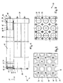
- a catalyst module 10 of a stationary catalyst system 1 to 3 is essentially cuboid, it has a cross section of 150 x 150 mm and one Length of 1000 mm.
- a module comprises nine cartridges 12 with one dimensionally stable inner jacket 14 with a diameter of approximately 34 mm and an outer jacket 16 made of a braided inorganic Fiber material that is stocking-like over the inner jacket 14 is pulled.
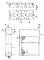
- the cartridges 12 are downstream with respect to an exhaust air flow 18 provided with a cap 20.
- the exhaust gas stream 18 enters the interior 28 of the cartridges 12 that are open upstream and passes through the porous inner jacket 14 and the fibrous Outer jacket 16 in the interior 26 between the Cartridges 12.
- the cleaned exhaust air 18 flows through openings in the cartridge holder 24.
- At the entrance end of the upstream open cartridges 12 is a coaxial via a clamping bracket 34 Flanged sleeve 30 attached.
- the sleeve 30 penetrates accordingly dimensioned openings 36 in the upstream filter cartridge holder 38.
- Cap 20 and flange sleeve 30 are connected to the inner jacket by spot welding, not gastight. The sealing is done by one front clamping bracket 34, which on the outer jacket 16th put on and in the area of the cap 20 and the Flange sleeve 30 are tightened.
- a multi-part clamping piece 40, 42 On the inside is a multi-part clamping piece 40, 42, which is shown in detail in FIG. 6, with the cartridge holder 38 screwed, the screw connection is designated 56.
- This Clamp is used to seal the interior on the inlet side 26 around the cartridges 12 and thus the prevention of Leakage currents.
- the seals are designated 44, 46.
- the dimensional stability of the catalyst module 10 is further improved, by the cartridge holder 24 having an inwardly folded edge 52, the cartridge holder 38 has a folded edge 54. At the Stacking modules 10 form the folded edges 52, 54 the contact surfaces.
- the bowl-shaped cartridge holder 24 On the outflow side of the catalyst module shown in FIG 10 is the bowl-shaped cartridge holder 24 with in essential square recesses.
- the above the caps 20 screwed cartridges on the face leave an interior space 26 downstream, which thanks to the openings 22 the cleaned exhaust air flows through without any problems becomes.
- the inner jacket 14 of a cartridge shown shortened in FIG. 4 12 (FIG. 1) comprises the closure cap at the downstream end 20 with a welding stud 48, which as Threaded rod is formed.
- a welding stud 48 which as Threaded rod is formed.
- a flange sleeve 30 also called a collar, mounted and spot welded to the inner jacket.
- Fig. 5 shows the spread, also shown shortened Inner jacket 14 according to FIG. 4.
- the porosity exists in regularly arranged round holes 58, which over the whole inner jacket 14 are distributed.
- the multi-part clamping piece of which one end and one middle piece 40, 42 are essentially shown in FIG. 6 semicircular recesses 60, which correspond in total to the number of cartridges to be accommodated.
- the recesses 60 are approximately 1 mm larger Radius than the flange sleeve 30.
- screw holes 62 provided which the attachment to the upstream Cartridge holder 38 (Fig. 1.3) serve.
- FIG. 7,8 show a mobile catalytic converter system 66 with an in a removable catalyst insert disposed in a catalyst housing 68 70.
- the housing is in a surrounding this Insulation layer 76 embedded.
- a stationary catalytic converter in the sense of Fig. 7,8 can be used instead of a catalyst 70 any number of catalyst modules 1 included.
- the exhaust air stream 18 to be cleaned flows over a flanged one Gas supply nozzle 90 into the catalyst housing 68 in the area of the catalyst insert 70, which is shown in FIG. 9 is shown in detail. Downstream is a gas discharge nozzle 78 am Flanged catalytic converter housing 68.
- a pipe 92 passes through adjacent to the gas discharge nozzle 78 with cable sheath the insulation layer 76 and the catalyst housing 68. It serves to introduce a measuring probe and is locked when not in use.
- FIG. 8 shows a radial section VII-VII according to FIG. 7.
- the catalyst insert 70 comprises nineteen cartridges 12 with inner jacket 14 and outer jacket 16.
- the catalyst housing 68 with the insulation layer 76 is from a clamping ring Surround 94, which can be determined with a screw 96 is.
- Fig. 8 is also shown as an example that within of the inner jacket 14 rod-shaped electrode elements for excitation the vapors and gases are arranged by means of electrical fields could be.
- the catalyst insert 70 shown in FIG. 9 corresponds essentially a catalyst module 10 according to FIG. 1 hexagonal design of the cartridge holder forming the outer circumference 24, 38 or from their folded edges 52, 54 (FIG. 1), the catalyst insert 70 becomes the catalyst module 10 with nineteen cartridges 12. The foremost cartridge 12 of the middle level is visible in full size, the rest are partially covered.
- the catalyst can be used 70 by creating more wreaths of cartridges be enlarged.
- the catalyst insert replaced by several catalyst modules.
- the cartridge holder 24 according to FIG. 10 on the outlet side corresponds essentially to Fig. 2. Because of the hexagonal The structure of the catalyst insert 70 is the openings 22 however triangular. The nineteen holes 98 are used to hold threaded bolts 48 (FIG. 4) for fastening of the cartridges, not shown. Analogue corresponds the cartridge holder 38 according to FIG. 11 of the previous FIG. 3. The numerous holes 100 are used to attach one multi-part clamping piece.
- the two terminal clamps 40 have on their straight On the long side three essentially semicircular recesses 60, which has a radius about 1 mm larger than that Have flange sleeves 30 (Fig. 4).
- the four middle clamps 41 have three to five corresponding on their long sides semicircular recesses 60. Between the Clamping pieces 40, 41 are each approximately 1 mm wide slot 104 recessed.
- the arrangement of the holes 100 for the screw connections 56 (Fig. 1.9) corresponds exactly to that of cartridge holder 38 arranged upstream.
- FIG. 13 shows a variant of the sealing of the interior 26 (Fig. 1,2) outside the cartridges in a catalyst module or catalyst insert.
- Adjacent to the face the inner jacket 14 is a spot welded flange sleeve 30 on.
- An abutting face of this flange sleeve Clamp 40, 42 presses when tightening the screws 56 (Fig. 1,9) the flange sleeve 30 against the seal 44 and the cartridge holder 38.
- the cartridges 12 do not have to be with one Seal held in the cartridge holder 38.
- a full flow exhaust air purification system 110 occurs according to 14 the exhaust air laden with hydrocarbons an exhaust air inlet 112 and a vetilator 114 in a treatment room 116.
- a catalyst 118 is arranged, which is designed as the device according to the invention.
- Before entering the Catalyst 118 can take the exhaust air through to the treatment room 16 connected hot air blower 120 preheated become. Leaves after exiting catalyst 118 the cleaned exhaust air the treatment room 116 via a Clean air outlet opening 122.
- a partial flow exhaust air purification system shown in FIG. 15 130 has an exhaust air inlet opening 132 and one adjoining fan 134.
- a catalyst 138 which is designed as the device according to the invention.
- To the treatment room 136 is a hot air blower for preheating air 140 upstream of the catalyst 138.
- the exhaust air flows out here first in an adsorption memory 144, in which Carbon monoxide or hydrocarbons are adsorbed.
- the exhaust air cleaned in this way leaves the adsorption store 144 via the clean air outlet opening 142.
- the loading of the adsorption storage 144 becomes the hydrocarbons by introducing a desorption gas via a desorption line 146 by means of a compressor 148 desorbed, possibly heated via the hot air blower 140 and then fed to the catalyst 138. After this Passing through the catalyst 138 is the cleaned Exhaust air via a connecting line 150 to the clean air outlet opening 142 out.
- the device according to the invention acts selectively particularly well for CO from approximately 150 ° C. and, depending on the temperature range and active material of the cartridges, well for C m H n .
Landscapes
- Engineering & Computer Science (AREA)
- Chemical & Material Sciences (AREA)
- Chemical Kinetics & Catalysis (AREA)
- Environmental & Geological Engineering (AREA)
- Mechanical Engineering (AREA)
- General Engineering & Computer Science (AREA)
- Health & Medical Sciences (AREA)
- Toxicology (AREA)
- Combustion & Propulsion (AREA)
- Exhaust Gas Treatment By Means Of Catalyst (AREA)
- Exhaust Gas After Treatment (AREA)
- Filtering Of Dispersed Particles In Gases (AREA)
- Electrical Discharge Machining, Electrochemical Machining, And Combined Machining (AREA)
Description
- Fig. 1 eine teilweise aufgeschnittene Seitenansicht eines Katalysatormoduls einer stationären Katalysatoranlage;
- Fig. 2 eine Stirnansicht des Moduls von der Abluftaustrittsseite;
- Fig. 3 eine Stirnansicht des Moduls von der Ablufteintrittsseite;
- Fig. 4 eine teilweise aufgeschnittene Ansicht einer Patrone;
- Fig. 5 eine teilweise detaillierte Ansicht des Innenmantels der Patrone;
- Fig. 6 eine Ansicht eines mehrteiligen Klemmstücks;
- Fig. 7 eine aufgeschnittene Ansicht einer mobilen Katalysatoranlage mit einem Katalysatoreinsatz;
- Fig. 8 einen Radialschnitt bei VIII - VIII in Fig. 7;
- Fig. 9 einen Katalysatoreinsatz für Fig. 7;
- Fig. 10 der stromab liegende Patronenhalter von Fig. 9;
- Fig. 11 der stromauf liegende Patronenhalter von Fig. 9;
- Fig. 12 ein Klemmstück des Katalysatoreinsatzes nach Fig. 9;
- Fig. 13 einen Axialschnitt durch eine Filterpatrone im Bereich der Eintrittsseite;
- Fig. 14 das Prinzip einer Vollstrom-Abluftreinigungsanlage;
- Fig. 15 das Prinzip einer Teilstrom-Abluftreinigungsanlage.
Claims (12)
- Vorrichtung zur Abluftreinigung gas- und dampfförmiger Stoffe, enthaltend ein von einem Abluftstrom (18) durchströmbares Gehäuse (68) mit mehreren axial in Abstand verlaufenden, einseitig verschlossenen Patronen (12), welche einen formfesten, perforierten Innenmantel (14) und einen mit geringem Widerstand gasdurchlässig ausgebildeten Außenmantel (16) als Träger mit aktivem Material für Katalyse, Adsorption oder Umsetzung von Schadstoffen in Gas aufweisen, wobei die Patronen (12) auf der Gaseintrittsseite mit einem ersten, im Bereich der Patronen (12) offenen Patronenhalter (38) verbunden sind und ferner auf der Gasaustrittsseite mit einem zweiten, im Bereich zwischen den Patronen (12) offenen Patronenhalter (24) lösbar verbunden sind,
dadurch gekennzeichnet, daß die Patronen (12) zu wenigstens einem aus dem Gehäuse (68) ausbaubaren Einsatz (70) oder ausbaubaren Modulen (10) zusammengefaßt sind,daß die Patronen (12) in dem Einsatz (70) oder Module (10) jeweils einzeln lösbar befestigt sind unddaß im Bereich des ersten Patronenhalters (38) Dichtmittel (40, 42, 44) zur Abdichtung des Patroneninnenraumes (28) bezüglich des außerhalb der jeweiligen Patrone (12) vorhandenen Raumes (26) vorgesehen sind. - Vorrichtung nach Anspruch 1, dadurch gekennzeichnet, daß die Patronen (12) mit den Trägern für Katalyse, Adsorption und Umsetzung von organischen Stäuben und Aerosolen im Gas in jeweils getrennten Gehäusen (68) bzw. Einheiten angeordnet sind.
- Vorrichtung nach Anspruch 1 oder 2, dadurch gekennzeichnet, daß der Außenmantel (16) aus aktivem Material aufgebaut oder mit diesem beschichtet ist.
- Vorrichtung nach einem der Ansprüche 1 bis 3, dadurch gekennzeichnet, daß die Patronen (12) stromauf mit Spiel von einem vorzugsweise mehrteiligen Klemmstück (40, 42) umfaßt sind, welches auf eine zwischen dem Klemmstück (40, 42) und dem Patronenhalter (38) eingelegte Dichtung (44) einwirkt und den Innenraum (26) außerhalb der Patronen (12) abdichtet.
- Vorrichtung nach Anspruch 4, dadurch gekennzeichnet, daß das Klemmstück (40, 42) im wesentlichen streifenförmig, mit im wesentlichen halbkreisförmig ausgebildeten Aussparungen (60) für die Patronen (12), ausgebildet ist.
- Vorrichtung nach einem der Ansprüche 1 bis 5, dadurch gekennzeichnet, daß eine stromab über dem Innenmantel (14) der Patronen (12) gestülpte Verschlußkappe (20), stromauf eine Flanschhülse (30) der Befestigung der Patronen (12) dient, wobei Verschlußkappe (20) und Flanschhülse (30) vorzugsweise durch Punktschweißen mit dem Innenmantel (14) verbunden sind.
- Vorrichtung nach Anspruch 6, dadurch gekennzeichnet, daß der Außenmantel (16) mit Klemmbriden (34) gasdicht auf der Verschlußkappe (20) und der Flanschhülse (30) befestigt ist.
- Vorrichtung nach einem der Ansprüche 1 bis 7, dadurch gekennzeichnet, daß die Halte- und Stützteile, insbesondere der Innenmantel (14) der Patronen (12) und die Patronenhalter (24, 28) aus hochlegiertem Stahl bestehen.
- Vorrichtung nach einem der Ansprüche 1 bis 8, dadurch gekennzeichnet, daß der Innenmantel (14) der Patronen (12) Rund- (58) und/oder Langlöcher aufweist oder als Draht- bzw. Bändergitter ausgebildet ist.
- Vorrichtung nach einem der Ansprüche 1 bis 9, dadurch gekennzeichnet, daß das aktive Material aus einer Einstoffbeschichtung oder einem Gemisch aus Edelmetallen oder aus Edelmetalloxiden, insbesondere aus Platin, Rhodium, Palladium, Vanadium, Kobalt oder deren Oxiden mit anderen Metallen bzw. deren Oxiden besteht.
- Vorrichtung nach einem der Ansprüche 1 bis 10, dadurch gekennzeichnet, daß der Träger bzw. der Außenmantel (16) der Patronen (12) aus Fasern, insbesondere aus verstrickten, verwebten oder geflochtenen Fasern aus Aktivkohle, Keramik oder Glas besteht.
- Vorrichtung nach einem der Ansprüche 1 bis 11, dadurch gekennzeichnet, daß die Module (10) mit einer elastischen Glasgewebeabdichtung gegeneinander abgedichtet sind.
Applications Claiming Priority (4)
| Application Number | Priority Date | Filing Date | Title |
|---|---|---|---|
| CH19095 | 1995-01-24 | ||
| CH19095 | 1995-01-24 | ||
| CH190/95 | 1995-01-24 | ||
| PCT/CH1996/000033 WO1996023134A1 (de) | 1995-01-24 | 1996-01-24 | Vorrichtung zur abluftreinigung gas- und dampfförmiger stoffe in einem abluftstrom |
Publications (2)
| Publication Number | Publication Date |
|---|---|
| EP0805915A1 EP0805915A1 (de) | 1997-11-12 |
| EP0805915B1 true EP0805915B1 (de) | 2000-03-22 |
Family
ID=4181307
Family Applications (1)
| Application Number | Title | Priority Date | Filing Date |
|---|---|---|---|
| EP96900497A Expired - Lifetime EP0805915B1 (de) | 1995-01-24 | 1996-01-24 | Vorrichtung zur abluftreinigung gas- und dampfförmiger stoffe in einem abluftstrom |
Country Status (5)
| Country | Link |
|---|---|
| EP (1) | EP0805915B1 (de) |
| AT (1) | ATE191061T1 (de) |
| AU (1) | AU4429496A (de) |
| DE (1) | DE59604776D1 (de) |
| WO (1) | WO1996023134A1 (de) |
Cited By (1)
| Publication number | Priority date | Publication date | Assignee | Title |
|---|---|---|---|---|
| DE102010053452A1 (de) * | 2010-12-06 | 2012-06-06 | Mann + Hummel Gmbh | Filtereinheit zur Abgasnachbehandlung von Brennkraftmaschinen |
Families Citing this family (2)
| Publication number | Priority date | Publication date | Assignee | Title |
|---|---|---|---|---|
| RU2167697C2 (ru) * | 1999-03-11 | 2001-05-27 | ПЕРМСКИЙ ЗАВОД им. С.М. КИРОВА | Устройство для очистки газов |
| JP4032902B2 (ja) * | 2002-09-25 | 2008-01-16 | トヨタ自動車株式会社 | 排気浄化用の基材、および、その製造方法 |
Citations (1)
| Publication number | Priority date | Publication date | Assignee | Title |
|---|---|---|---|---|
| WO1993003112A1 (en) * | 1991-08-02 | 1993-02-18 | Ronald Peter Hansen | Solution for watering plant roots |
Family Cites Families (9)
| Publication number | Priority date | Publication date | Assignee | Title |
|---|---|---|---|---|
| US3847574A (en) * | 1973-03-14 | 1974-11-12 | American Air Filter Co | Charcoal filter arrangement |
| US3969095A (en) * | 1973-08-25 | 1976-07-13 | Shigeru Kurahashi | Air filter apparatus |
| US4018568A (en) * | 1976-02-09 | 1977-04-19 | Uop Inc. | Fume absorbing-treating system |
| DE3007639A1 (de) * | 1980-02-29 | 1981-09-17 | Daimler-Benz Ag, 7000 Stuttgart | Russfilter im abgasstrom einer brennkraftmaschine |
| DE3823205A1 (de) * | 1988-07-08 | 1990-01-11 | Eberspaecher J | Russfilterkerze fuer die reinigung von abgasen und aus russfilterkerzen gebildete russfilteranordnung |
| EP0410200A1 (de) * | 1989-07-12 | 1991-01-30 | Sintermetallwerk Krebsöge Gmbh | Durchlässig-poröser Körper zur Behandlung von Gasen und/oder Dämpfen und/oder Flüssigkeiten und Verfahren zu seiner Herstellung |
| US5258164A (en) * | 1991-04-05 | 1993-11-02 | Minnesota Mining And Manufacturing Company | Electrically regenerable diesel particulate trap |
| WO1994021351A1 (en) * | 1993-03-17 | 1994-09-29 | Massachusetts Institute Of Technology | Active filters for integrated cleanup of gas streams |
| NO932152L (no) * | 1993-06-11 | 1994-12-12 | Abb Miljoe Norsk Viftefab | Adsorpsjonsfilter |
-
1996
- 1996-01-24 DE DE59604776T patent/DE59604776D1/de not_active Expired - Fee Related
- 1996-01-24 EP EP96900497A patent/EP0805915B1/de not_active Expired - Lifetime
- 1996-01-24 AU AU44294/96A patent/AU4429496A/en not_active Abandoned
- 1996-01-24 AT AT96900497T patent/ATE191061T1/de not_active IP Right Cessation
- 1996-01-24 WO PCT/CH1996/000033 patent/WO1996023134A1/de not_active Ceased
Patent Citations (1)
| Publication number | Priority date | Publication date | Assignee | Title |
|---|---|---|---|---|
| WO1993003112A1 (en) * | 1991-08-02 | 1993-02-18 | Ronald Peter Hansen | Solution for watering plant roots |
Cited By (1)
| Publication number | Priority date | Publication date | Assignee | Title |
|---|---|---|---|---|
| DE102010053452A1 (de) * | 2010-12-06 | 2012-06-06 | Mann + Hummel Gmbh | Filtereinheit zur Abgasnachbehandlung von Brennkraftmaschinen |
Also Published As
| Publication number | Publication date |
|---|---|
| EP0805915A1 (de) | 1997-11-12 |
| ATE191061T1 (de) | 2000-04-15 |
| AU4429496A (en) | 1996-08-14 |
| WO1996023134A1 (de) | 1996-08-01 |
| DE59604776D1 (de) | 2000-04-27 |
Similar Documents
| Publication | Publication Date | Title |
|---|---|---|
| EP0633065B1 (de) | Vorrichtung zur Reinigung schadstoffbeladener Abluft durch heterogene Katalyse | |
| DE69314928T2 (de) | Abgasreinigung | |
| DE4290489C2 (de) | Abgasreinigungssystem für einen Dieselmotor und Verfahren zum Regenerieren von Keramikfiltern | |
| DE4420224C2 (de) | Verfahren zur Entfernung unerwünschter Beimengungen eines Gases | |
| DE69201065T2 (de) | Abgasentgiftungsanlage. | |
| WO1998048922A1 (de) | Vorrichtung und verfahren zur zersetzung von schadstoffen in abgasen von verbrennungsprozessen | |
| WO1998048922B1 (de) | Vorrichtung und verfahren zur zersetzung von schadstoffen in abgasen von verbrennungsprozessen | |
| DE10238770A1 (de) | Vorrichtung zur Entfernung von Rußpartikeln aus dem Abgas eines Dieselmotors | |
| DE4026375C1 (de) | ||
| DE69505959T2 (de) | Behandlung von abgas eines fliessbett-druckreaktionssystems | |
| DE69204061T2 (de) | Abgasfilter. | |
| EP0603986B1 (de) | Vorrichtung zur Reinigung schadstoffbeladener Abluft | |
| EP0561484B1 (de) | Verfahren und Vorrichtung zur Reinigung schadstoffbeladener Abluft durch heterogene Katalyse | |
| EP0805915B1 (de) | Vorrichtung zur abluftreinigung gas- und dampfförmiger stoffe in einem abluftstrom | |
| CH689687A5 (de) | Russfilteranlage. | |
| WO1992019849A1 (de) | Filtereinrichtung und verfahren zur abgasreinigung durch filtration | |
| DE19717890C5 (de) | Verfahren und Vorrichtung zur plasmagestützten Zersetzung von Ruß in Verbrennungsabgasen | |
| DE2541011A1 (de) | Verfahren zur reinigung von verunreinigter luft | |
| EP0342588B1 (de) | Abgasreinigungsverfahren und -vorrichtung mit Wabenkörpern aus Calciumverbindungen | |
| DE1907027C3 (de) | Vorrichtung zur Behandlung einer Verbindung in der Gasphase an einem Feststoff | |
| DE69808336T2 (de) | Zikoniumoxid enthaltende vorrichtung zur plasmagestützten gasbehandlung | |
| DE19651822C2 (de) | Verfahren zur Verringerung der PCDD- und/oder PCDF-Konzentration in Abgasen | |
| DE19652403A1 (de) | Anordnung und Verfahren zur oxidativen Abgasreinigung | |
| DE3514151A1 (de) | Vorrichtung zur kontinuierlichen reinigung von teilchenfiltern, insbesondere fuer dieselmotorabgasfilter | |
| DE10126665A1 (de) | Vorrichtung zum Aufbereiten eines Stoffstroms |
Legal Events
| Date | Code | Title | Description |
|---|---|---|---|
| PUAI | Public reference made under article 153(3) epc to a published international application that has entered the european phase |
Free format text: ORIGINAL CODE: 0009012 |
|
| 17P | Request for examination filed |
Effective date: 19970725 |
|
| AK | Designated contracting states |
Kind code of ref document: A1 Designated state(s): AT CH DE FR GB IT LI NL SE |
|
| 17Q | First examination report despatched |
Effective date: 19980108 |
|
| GRAG | Despatch of communication of intention to grant |
Free format text: ORIGINAL CODE: EPIDOS AGRA |
|
| GRAG | Despatch of communication of intention to grant |
Free format text: ORIGINAL CODE: EPIDOS AGRA |
|
| GRAH | Despatch of communication of intention to grant a patent |
Free format text: ORIGINAL CODE: EPIDOS IGRA |
|
| GRAH | Despatch of communication of intention to grant a patent |
Free format text: ORIGINAL CODE: EPIDOS IGRA |
|
| GRAA | (expected) grant |
Free format text: ORIGINAL CODE: 0009210 |
|
| AK | Designated contracting states |
Kind code of ref document: B1 Designated state(s): AT CH DE FR GB IT LI NL SE |
|
| REF | Corresponds to: |
Ref document number: 191061 Country of ref document: AT Date of ref document: 20000415 Kind code of ref document: T |
|
| REG | Reference to a national code |
Ref country code: CH Ref legal event code: EP |
|
| REF | Corresponds to: |
Ref document number: 59604776 Country of ref document: DE Date of ref document: 20000427 |
|
| ITF | It: translation for a ep patent filed | ||
| GBT | Gb: translation of ep patent filed (gb section 77(6)(a)/1977) |
Effective date: 20000519 |
|
| ET | Fr: translation filed | ||
| PLBE | No opposition filed within time limit |
Free format text: ORIGINAL CODE: 0009261 |
|
| STAA | Information on the status of an ep patent application or granted ep patent |
Free format text: STATUS: NO OPPOSITION FILED WITHIN TIME LIMIT |
|
| PG25 | Lapsed in a contracting state [announced via postgrant information from national office to epo] |
Ref country code: GB Free format text: LAPSE BECAUSE OF NON-PAYMENT OF DUE FEES Effective date: 20010124 Ref country code: AT Free format text: LAPSE BECAUSE OF NON-PAYMENT OF DUE FEES Effective date: 20010124 |
|
| PG25 | Lapsed in a contracting state [announced via postgrant information from national office to epo] |
Ref country code: SE Free format text: LAPSE BECAUSE OF NON-PAYMENT OF DUE FEES Effective date: 20010125 |
|
| 26N | No opposition filed | ||
| PGFP | Annual fee paid to national office [announced via postgrant information from national office to epo] |
Ref country code: CH Payment date: 20010430 Year of fee payment: 6 |
|
| PG25 | Lapsed in a contracting state [announced via postgrant information from national office to epo] |
Ref country code: NL Free format text: LAPSE BECAUSE OF NON-PAYMENT OF DUE FEES Effective date: 20010801 |
|
| PGFP | Annual fee paid to national office [announced via postgrant information from national office to epo] |
Ref country code: DE Payment date: 20010831 Year of fee payment: 6 |
|
| EUG | Se: european patent has lapsed |
Ref document number: 96900497.7 |
|
| GBPC | Gb: european patent ceased through non-payment of renewal fee |
Effective date: 20010124 |
|
| NLV4 | Nl: lapsed or anulled due to non-payment of the annual fee |
Effective date: 20010801 |
|
| PG25 | Lapsed in a contracting state [announced via postgrant information from national office to epo] |
Ref country code: LI Free format text: LAPSE BECAUSE OF NON-PAYMENT OF DUE FEES Effective date: 20020131 Ref country code: CH Free format text: LAPSE BECAUSE OF NON-PAYMENT OF DUE FEES Effective date: 20020131 |
|
| PG25 | Lapsed in a contracting state [announced via postgrant information from national office to epo] |
Ref country code: FR Free format text: LAPSE BECAUSE OF NON-PAYMENT OF DUE FEES Effective date: 20020329 |
|
| REG | Reference to a national code |
Ref country code: FR Ref legal event code: ST |
|
| PG25 | Lapsed in a contracting state [announced via postgrant information from national office to epo] |
Ref country code: DE Free format text: LAPSE BECAUSE OF NON-PAYMENT OF DUE FEES Effective date: 20020801 |
|
| REG | Reference to a national code |
Ref country code: CH Ref legal event code: PL |
|
| PG25 | Lapsed in a contracting state [announced via postgrant information from national office to epo] |
Ref country code: IT Free format text: LAPSE BECAUSE OF NON-PAYMENT OF DUE FEES;WARNING: LAPSES OF ITALIAN PATENTS WITH EFFECTIVE DATE BEFORE 2007 MAY HAVE OCCURRED AT ANY TIME BEFORE 2007. THE CORRECT EFFECTIVE DATE MAY BE DIFFERENT FROM THE ONE RECORDED. Effective date: 20050124 |
|
| PG25 | Lapsed in a contracting state [announced via postgrant information from national office to epo] |
Ref country code: FR Free format text: LAPSE BECAUSE OF NON-PAYMENT OF DUE FEES Effective date: 20010131 |