EP0805890B1 - Drucksortierer zum sortieren von fasersuspensionen sowie sieb für einen solchen drucksortierer - Google Patents
Drucksortierer zum sortieren von fasersuspensionen sowie sieb für einen solchen drucksortierer Download PDFInfo
- Publication number
- EP0805890B1 EP0805890B1 EP95907639A EP95907639A EP0805890B1 EP 0805890 B1 EP0805890 B1 EP 0805890B1 EP 95907639 A EP95907639 A EP 95907639A EP 95907639 A EP95907639 A EP 95907639A EP 0805890 B1 EP0805890 B1 EP 0805890B1
- Authority
- EP
- European Patent Office
- Prior art keywords
- screen
- approximately
- sieve
- axis
- grooves
- Prior art date
- Legal status (The legal status is an assumption and is not a legal conclusion. Google has not performed a legal analysis and makes no representation as to the accuracy of the status listed.)
- Expired - Lifetime
Links
- 239000000835 fiber Substances 0.000 title claims description 69
- 239000000725 suspension Substances 0.000 title claims description 56
- 239000007788 liquid Substances 0.000 claims description 4
- 229910001220 stainless steel Inorganic materials 0.000 claims description 4
- 239000010935 stainless steel Substances 0.000 claims description 4
- 239000010893 paper waste Substances 0.000 claims description 2
- 238000012545 processing Methods 0.000 claims description 2
- 238000005520 cutting process Methods 0.000 claims 1
- 238000011144 upstream manufacturing Methods 0.000 description 48
- 239000000463 material Substances 0.000 description 9
- 230000002093 peripheral effect Effects 0.000 description 6
- 230000009467 reduction Effects 0.000 description 6
- 230000004323 axial length Effects 0.000 description 5
- 238000013461 design Methods 0.000 description 4
- 239000012535 impurity Substances 0.000 description 4
- 230000001154 acute effect Effects 0.000 description 3
- 230000000694 effects Effects 0.000 description 3
- 229910000831 Steel Inorganic materials 0.000 description 2
- 230000035508 accumulation Effects 0.000 description 2
- 238000009825 accumulation Methods 0.000 description 2
- 230000008901 benefit Effects 0.000 description 2
- 230000007423 decrease Effects 0.000 description 2
- 238000002474 experimental method Methods 0.000 description 2
- 238000003754 machining Methods 0.000 description 2
- 238000004519 manufacturing process Methods 0.000 description 2
- 238000000034 method Methods 0.000 description 2
- 238000003801 milling Methods 0.000 description 2
- 230000008569 process Effects 0.000 description 2
- 230000003068 static effect Effects 0.000 description 2
- 239000010959 steel Substances 0.000 description 2
- 239000000126 substance Substances 0.000 description 2
- 238000005452 bending Methods 0.000 description 1
- 230000008859 change Effects 0.000 description 1
- 238000010276 construction Methods 0.000 description 1
- 239000000356 contaminant Substances 0.000 description 1
- 230000003247 decreasing effect Effects 0.000 description 1
- 230000001419 dependent effect Effects 0.000 description 1
- 238000011161 development Methods 0.000 description 1
- 230000018109 developmental process Effects 0.000 description 1
- 238000010894 electron beam technology Methods 0.000 description 1
- 238000005516 engineering process Methods 0.000 description 1
- 239000000945 filler Substances 0.000 description 1
- 239000012530 fluid Substances 0.000 description 1
- 238000011010 flushing procedure Methods 0.000 description 1
- 239000006260 foam Substances 0.000 description 1
- -1 from wires Substances 0.000 description 1
- 238000009434 installation Methods 0.000 description 1
- 239000002184 metal Substances 0.000 description 1
- 230000002829 reductive effect Effects 0.000 description 1
- 230000000717 retained effect Effects 0.000 description 1
- 239000004576 sand Substances 0.000 description 1
- 238000012549 training Methods 0.000 description 1
- 239000002699 waste material Substances 0.000 description 1
- 230000003313 weakening effect Effects 0.000 description 1
- 238000003466 welding Methods 0.000 description 1
Images


Classifications
-
- D—TEXTILES; PAPER
- D21—PAPER-MAKING; PRODUCTION OF CELLULOSE
- D21D—TREATMENT OF THE MATERIALS BEFORE PASSING TO THE PAPER-MAKING MACHINE
- D21D5/00—Purification of the pulp suspension by mechanical means; Apparatus therefor
- D21D5/02—Straining or screening the pulp
- D21D5/023—Stationary screen-drums
- D21D5/026—Stationary screen-drums with rotating cleaning foils
-
- D—TEXTILES; PAPER
- D21—PAPER-MAKING; PRODUCTION OF CELLULOSE
- D21D—TREATMENT OF THE MATERIALS BEFORE PASSING TO THE PAPER-MAKING MACHINE
- D21D5/00—Purification of the pulp suspension by mechanical means; Apparatus therefor
- D21D5/02—Straining or screening the pulp
- D21D5/16—Cylinders and plates for screens
-
- Y—GENERAL TAGGING OF NEW TECHNOLOGICAL DEVELOPMENTS; GENERAL TAGGING OF CROSS-SECTIONAL TECHNOLOGIES SPANNING OVER SEVERAL SECTIONS OF THE IPC; TECHNICAL SUBJECTS COVERED BY FORMER USPC CROSS-REFERENCE ART COLLECTIONS [XRACs] AND DIGESTS
- Y10—TECHNICAL SUBJECTS COVERED BY FORMER USPC
- Y10T—TECHNICAL SUBJECTS COVERED BY FORMER US CLASSIFICATION
- Y10T29/00—Metal working
- Y10T29/49—Method of mechanical manufacture
- Y10T29/496—Multiperforated metal article making
- Y10T29/49604—Filter
Definitions
- the invention relates to a sieve according to the preamble of the claim 1 and a pressure sorter according to the preamble of Claim 24.
- the invention relates to such screens, at which the upstream grooves and the sieve passage channels in a screen wall that is rotationally symmetrical to the screen axis from one stainless steel sheet are formed, or such pressure sorters, as described in WO 94/00634 from Hermann Finckh Maschinenfabrik GmbH & Co. reveals and claims become.
- a sieve with the features of the preamble of claim 1 can be seen from Figures 14 to 16 of EP-A-0 205 623. How 14 of this document, the upstream grooves continuously over the entire axial length the effective part of the sieve, and each of these grooves are assigned several slot-shaped sieve passage channels, which follow each other in the direction of the sieve axis and from each other are spaced.
- the profile of the upstream grooves is like this designed that the to be sorted in the direction of rotation Fiber suspension in front of the groove side wall - in section perpendicular to the screen axis - one with the screen circumferential direction Forms an angle of 90 ° and the two groove side walls with each other form an angle of approximately 135 °.
- the in the circumferential direction measured width of the non-profiled and Surface areas running parallel to the circumferential direction of the screen of the screen between the successive ones in the screen circumferential direction Grooves is significantly larger than that on the Upstream side of the sieve and also in the circumferential direction of the sieve measured width of the grooves.
- the two Groove side walls are opposite to the screen circumferential direction, respectively inclined at an angle of 45 ° so that they join together Form an angle of 90 °.
- the groove depth is 1 mm, the in The groove width measured as a result of this is 2 mm.
- the invention was based on the task of a sieve has upstream turbulence-generating grooves, or to create a pressure sorter with such a sieve which has a higher throughput than with the above known sieves or pressure sorters described with such Seven can be achieved without including his Wear behavior dependent durability or service life of the sieve.
- This task can be done according to the invention with a sieve Solve claim 1 or a pressure sorter according to claim 25.
- EP-A-0 521 192 discloses a cylindrical sieve for sorting of fiber suspensions become known, the screen wall has recesses on the upstream side of the sieve, in the each has a plate-shaped sieve insert, which a series of perpendicular to the platelet plane Has holes; these holes form the fineness of sorting determining sieve passage channels, and to each upstream
- One recess belongs from the downstream side of the Siebs forth in the sieve wall made hole, the axis runs perpendicular to the screen wall and its diameter is so large is dimensioned that all holes of the sieve insert in this Hole.
- the recesses in which the sieve inserts are used when looking at the screen wall in the direction either circular or perpendicular to the sieve axis a rectangular shape, the longitudinal direction being rectangular Recesses in the circumferential direction of the screen or in the direction of Sieve axis can run (see Fig. 6).
- the embodiment shown in EP-A-0 521 192 forms the Plane-shaped sieve insert plane with the circumferential direction of the sieve an acute angle of 25 ° to 45 °, and rectangular Recesses and thus rectangular sieve inserts form the flanks of the upstream side in the upstream direction Recesses with a circumferential direction Angles from 45 ° to 65 °.
- the properties of the sieve according to the invention with regard to the achievable throughput and its operating behavior can be improved more and more, the more the inclination the front groove side wall opposite the wire circumferential direction approximately an angle of approximately 52 ° or approximately 53 ° and an optimum results at an angle of inclination of 52.5 °, especially when the sieve passage is exact flows into the bottom of the groove and flows radially with respect to the sieve axis becomes.
- an optimal value of the groove depth is approximately 1 mm.
- the upstream grooves with any known Machining technology could be produced, e.g. B. in that the metal in the area of the grooves to be produced by means of an energy beam (laser or electron beam) is evaporated (the sieve passage channels could also be such energy beam are produced), it is recommended at the current state of the art, for reasons of manufacturing costs and the precision of those to be generated in the screen wall Contours the grooves as created by machining Form wells, so that they are particularly means a milling cutter.
- an energy beam laser or electron beam
- the screen wall of a steel sheet is produced for the screen wall - outside of the upstream side with screen openings connecting the outflow side - a wall thickness of about 6 mm to about 10 mm and in particular from about 6 mm to about 8 mm.
- a motor 18 standing on a frame 16 which is is a three-phase or 3-phase AC motor, which by means of a pulley 20 and V-belt 22 a Pulley 24 drives which on a in the frame 16th and the housing 14 rotatably mounted rotor shaft 26 is.
- the housing 14 essentially consists of one according to FIG. 1 left end wall 28, a circular cylindrical, concentric to the rotor shaft 26 arranged casing 30 and a Housing cover 32, which are connected together pressure-tight are.
- An axis of the pressure sorter, which is also the axis the rotor shaft 26 is designated 34.
- the rotor shaft guided through the end wall 28 in a pressure-tight manner 26 carries a rotor designated as a whole by 36, which can be driven about the axis 34 by means of the rotor shaft 26 is and of a circular cylindrical, concentric to the axis 34 Sieve 38 is surrounded, the two on the housing jacket 30 attached annular housing elements 40 and 42 is attached and held by these housing rings becomes.
- the axial length is (in the direction of the axis 34) of the rotor 36 equal to the axial Length of the effective area of the screen 38 between the housing rings 40 and 42. It would also be possible to achieve certain effects, the axial length of the rotor 36 larger or less than the axial length of the sieve 38.
- the housing 14 At the right end of the housing 14 according to FIG. 1 there is an inlet connection 46 provided by - as indicated by the arrow F. -
- the fiber suspension to be processed or sorted is promoted in the pressure sorter, namely by means of a pump, not shown.
- the outlet connection 48 on the housing jacket 30 attached, through which the so-called accept material - as by the Arrow A indicated - leaves the pressure sorter. With the accepted material is that part of the fiber suspension which has passed the sieve 38.
- the housing shell 30 At the left end according to FIG. 1 the housing shell 30 is finally a second outlet port 50 attached, through which the so-called rejects - as indicated in Fig. 2 by the arrow R - the pressure sorter leaves; the reject is the one Part of the fiber suspension to be processed, which the sieve 38 cannot pass.
- inlet space 54 namely the fiber suspension to be sorted enters via first axial end 54a of this inlet space in the latter on.
- the axis 34 extends at least approximately horizontally, but in principle it would also be conceivable that Set up the sorter so that its axis 34 at least runs approximately vertically.
- a measuring device 60 which comprises a first pressure transmitter 62 and a second pressure transmitter 64, which are arranged in the inlet connection 46 and in the first outlet connection 48, but also also in the inlet chamber 52 or in the accept material chamber 58 could be.
- a difference former 74 which delivers at its output a control signal proportional to the pressure difference, which is applied via line 76 to the control input of a frequency converter 78.
- This is fed from a current source, not shown, with a 3-phase alternating current or three-phase current of frequency f 1 and supplies a three-phase current of frequency f 2 for driving three-phase motor 18, frequency f 2 being a function of the control signal generated by difference generator 74.
- the rotor 36 is driven at a speed which is a function of this control signal and thus the pressure difference between the inlet space 54 and the accept material space 58.
- potentiometers or other actuating elements could also be provided in the lines 66 and 68, with which the signals supplied by the pressure transmitters 62 and 64 could be changed, so as to make the dependence on the line 76 possible To be able to influence the control signal from the pressure difference mentioned.
- a hub 80 which is fixedly connected to the rotor shaft 26 carries a closed, hollow circular cylindrical rotor body 82 with a circular cylindrical rotor shell 84.
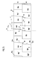
- This has a first axial end 84a at the first axial end 54a of the inlet space 54 and a second axial end 84b at the second axial end 54b of the inlet space and carries two sets outside of profile elements, namely a first set, which of Profile elements 86a, 86b, 86c and 86d is formed, as well a second set, formed by profile elements 88a, 88b, 88c and 88d.
- the first set of profile elements forms one itself in the rotor circumferential direction or direction of rotation U des Rotor's first row of profile elements and in between arranged gaps 86a ', 86b', 86c 'and 86d', and this row defines a first axial rotor section 90, which faces the inlet space 52;
- the second set of Profile elements 88a-88d form a second, just the same Row of profile elements and gaps arranged between them 88a ', 88b', 88c 'and 88d', and this second row defines a second axial rotor section 92 which is the reject space 56 is adjacent.
- all profile elements are of equal height (in Direction of the axis 34 measured), depending on the desired sorting result and / or depending on the type of sorting fiber suspension, however, could be appropriate be to choose the height of the first row larger or smaller than the height of the second row. It can also be useful be to provide the rotor with more than two such rows.
- each profile element one lying in the direction of rotation U at the front End face or first flank I, which is perpendicular to the circular cylindrical Outer peripheral surface of the rotor shell 84 and thus to the area in front of it in the direction of rotation U. Gap runs, as well as a directly on the first edge I. subsequent back surface or second flank II, which against the direction of rotation U in the radial direction to the inside and thus to the axis 34, so that the Profile elements in cross section perpendicular to axis 34 which have a very acute triangle equal, which was bent concentrically to axis 34.
- first flanks I become strong positive in the inlet area 54 Pressure surges and strong turbulence are generated, also with the first flanks I the fiber suspension in the inlet space 54 greatly accelerated, at most up to the rotational speed of the profile elements.
- Particularly strong Turbulence occurs in the inlet space 54 as a result of the in Direction of rotation U directed flow component of the Fiber suspension when the inside of the sieve 38 "Rough" according to the invention, i.e. is profiled.
- the first edges I run in preferred embodiments of the pressure sorter according to the invention not in parallel to axis 34, but form with the direction of axis 34 an acute angle a, namely the flanks I are opposite the direction of the axis 34 so inclined that thereby the in Flow component of the direction of the axis 34 Fiber suspension in the inlet space 54 in the direction of the first axial end 54a of the inlet space to its second axial End 54b is reinforced.
- the profile elements 86a-86d of the first row - measured in the rotor circumferential direction or direction of rotation U - are shorter than the profile elements 88a-88d of the second row.
- This measure serves the purpose of adapting the effect of the profile elements to the different consistency of the fiber suspension, the consistency of which increases in the inlet space 54 from its first end 54a to its second end 54b.
- each of the profile elements 86a-86d of the first row extends over a circumferential angle of 45 ° (this is the maximum length L 1 of the profile elements)
- the length of the profile elements to the second axial end 84b of the Rotor jacket 84 decreases because the first flanks I run obliquely to the direction of the axis 34, while the rear edges of the second flanks II are aligned parallel to the axis 34.
- the smallest length L 1 'of the gaps 86a' - 86d 'of the first row is also 45 ° and is therefore equal to the greatest length L 1 of the profile elements of this row, the length of the gaps in the direction of the second axial end 84b of the rotor shell 84 increases.
- the maximum length L 2 of the profile elements 88a-88d of the second row is 53 ° in this embodiment; since the number of profile elements of the second row is equal to the number of profile elements of the first row, the minimum length L 2 'of the gaps 88a' - 88d 'of the second row results in a lower value of 37 ° here.
- the profile elements 88a-88d of the second row and thus their gaps are offset with respect to the profile elements of the first row or their gaps against the direction of rotation U, the size of the offset thus being based on the lengths of the profile elements or the gaps are coordinated so that gaps of the two rows which are adjacent to one another in the axial direction overlap in the direction of rotation U or in the rotor circumferential direction to such an extent that they form a continuous channel in the axial direction which extends from one axial end 84a of the rotor shell 84 to whose other axial end 84b extends.
- the inside width L 3 of this channel is 25 °, the inside width being understood as the width which the observer sees in the direction of the axis 34 when the rotor is viewed from the front.
- the Lengths of the profile elements of the first row are approximately equal to the lengths of the gaps in the first row
- the lengths of the Profile elements of the second row are larger than the lengths the profile elements of the first row
- the lengths of the Gaps in the second row are smaller than the lengths of the Profile elements of the second row and smaller than the lengths the gaps in the first row.
- the lengths of the profile elements and the gaps were expressed in circumferential angles above.
- the lengths L 1 and L 2 are in a range between approximately 200 mm and approximately 450 mm.
- peripheral speeds achieved by adjusting the rotor speed the rotor are expediently between about 10 m / s and about 40 m / s, generally the best sorting results with circumferential speeds of approximately 15 to about 30 m / s can be reached.
- the sieve openings 38a of the sieve 38 are concerned Bores, their diameter is conveniently included approx. 1 mm to approx. 3.5 mm if the rotor with a peripheral speed is operated from approx. 10 to approx. 15 m / s. At higher peripheral speeds can have smaller holes be used; expediently one operates according to the invention Pressure sorter with circumferential rotor speeds from approx. 15 to approx. 40 m / s and then selects for the sieve openings Bores with a diameter of approx. 0.5 to approx. 1.5 mm. Are the screen openings 38a Slots, so these should be at rotor peripheral speeds from approx. 10 to approx. 15 m / s a width of approx.
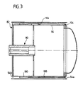
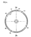
- FIGS. 3 and 4 86a-86d and 88a-88d of the preferred shown Embodiment.
- Each of these profile elements exists - sees one looks from the rotor jacket 84 - the first flank from one I forming bar 100, one forming the second flank II curved sheet 102 and two side walls 104, with respect 3 should be noted that in this Figure because of the oblique course of the first flanks I and so that the last 100 bars not perpendicular to theirs Longitudinal extension, but were cut at an angle to it.
- Those of the rotor jacket 84, the strips 100, the sheets 102 and the side walls 104 enclosed cavities 106 of the profile elements should be liquid tight or with a filler, such as. a foam plastic, to be filled in to avoid the creation of imbalances in the rotor. Same thing applies to the cavity of the rotor body 82.
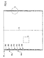
- FIGS. 6 and 8 there are 300 in the wall of the screen 38 around the screen axis 34 a plurality of rows 302 (6 rows in the illustrated embodiment) of screen openings 38a formed between which annular webs 304 are provided, in the areas of which the screen wall 300 has neither screen openings nor a surface profile.
- FIG. 6 shows forms the inner surface of the circular cylindrical, concentric to the axis 34 Siebs 38 whose upstream side 306, its outer surface the downstream side 308 of the sieve.
- FIGS. 7-9 and in particular using FIG. 9 are now the inventive design and arrangement of Sieve openings 38a are explained in more detail, wherein for a simpler drawing in Fig. 9 the screen wall 300 was drawn in the flat, flat state, e.g. B. So in the state in which the stainless steel sheet existing screen wall 300 during processing and before the bending and welding to a circular cylinder.
- each of the sieve openings 38a consists of four components, which partially overlap each other, namely from three Grooves and a slot. From the one forming the screen wall 300 Sheet was made for each screen opening 38a from the inflow side 306 Here, an inlet-side groove 400 is milled out from the outflow side 308 ago first an inner groove 402 and then one outer groove 404, the opening angle of which is larger than that the inner groove 402. Then a slot was finally made in the screen wall 300 sawn, which one of the grooves 400 and 402 interconnecting sieve passage 406 forms.
- each screen opening 38a The various components of each screen opening 38a are arranged relative to each other so that after Bend the screen wall 300 to the circular cylindrical screen 38 all on a diameter plane 408 containing the sieve axis 34 lie - this diameter plane represents the middle plane of the slot-shaped sieve passage 406, as well as the Center planes of the grooves 402 and 404, which are to this diameter plane 408 are designed symmetrically, and finally the base of the groove 400 also lies on the diameter plane 408.
- Siebs is approximately the total thickness of the sieve wall 6 mm, the one measured perpendicular to the inflow side 306
- the depth of the groove 400 is 1 mm, the distance between the just formed Bottom of the groove 402 from the downstream side is 308 4 mm, and the groove 404 should be 0.72 mm deep.
- the opening angle (measured in the plane of the drawing in FIG. 9) inner groove 402 should be 16 °, that of the outer groove 404 120 °. It follows from this that on the outflow side 308 measured the width measured in the circumferential direction of the sieve the outer groove 404 is 2.5 mm.
- the one in the same direction measured width (also called slot width) of the slot-shaped Sieve passage 406 depends on the desired fineness of sorting of the sieve and is in particular 0.1 mm to 0.25 mm.
- each of the grooves 400 now has a steeper one front groove side wall 400a and a flatter rear Groove sidewall 400b, which is preferred in the illustrated Embodiment form an angle of 97.5 ° with one another, while the angle a between the front groove side wall 400a and the diameter plane 408 is 37.5 °, the angle ⁇ between the diameter plane 408 and the rear groove side wall 400b 60 °.
Landscapes
- Engineering & Computer Science (AREA)
- Mechanical Engineering (AREA)
- Paper (AREA)
- Nonwoven Fabrics (AREA)
Description
- Fig. 1
- eine teilweise geschnittene Seitenansicht des erfindungsgemäßen Drucksortierers, wobei die Schnittdarstellung ein Schnitt in einer vertikalen Durchmesserebene des Rotors bzw. Siebs ist;
- Fig. 2
- einen Schnitt nach der Linie 2-2 in Fig. 1;
- Fig. 3
- Sieb und Rotor des Drucksortierers wie in Fig. 1 dargestellt, jedoch in größerem Maßstab als in Fig. 1, wobei auch hier das Sieb nur schematisch angedeutet wurde;
- Fig. 4
- eine Stirnansicht des Rotors, gemäß Fig. 1 von links gesehen, und zwar samt in einem axialen Schnitt dargestelltem Sieb;
- Fig. 5
- eine Abwicklung des Rotorumfangs, d.h. eine Draufsicht auf die gesamte Rotorumfangsfläche, welche jedoch in einer Ebene dargestellt wurde;
- Fig. 6
- einen Schnitt durch eine bevorzugte Ausführungsform des erfindungsgemäßen Siebs längs einer die Achse 34, welche auch die Siebachse darstellt, enthaltenden Durchmesserebene (allerdings wurden in Fig. 6 die bei einer Ansicht der Anströmseite des Siebs sichtbaren Details der Einfachheit halber weggelassen);
- Fig. 7
- den Ausschnitt "X" aus Fig. 6 in größerem Maßstab bzw. einen Schnitt nach der Linie 7-7 in Fig. 8;
- Fig. 8
- den Ausschnitt "Y" aus Fig. 6 in größerem Maßstab, und
- Fig. 9
- einen Schnitt durch einen Teil der Siebwand entsprechend der Linie 9-9 in Fig. 8.
Claims (25)
- Sieb (38) zum Sortieren von Fasersuspensionen, welches zu einer Siebachse (34) rotationssymmetrisch ausgebildet ist sowie eine Anströmseite (306) für die zu sortierende Fasersuspension und eine dieser gegenüberliegende Abströmseite (308) besitzt, für Drucksortierer (10) mit einem um die Siebachse (34) rotatorisch antreibbaren Rotor (36), welcher der Anströmseite (306) dieses Siebs (38) benachbart umlaufende Profilelemente (86a - 86d, 88a - 88d) zur Erzeugung positiver und negativer Druckstöße in der zu sortierenden Fasersuspension besitzt, wobei das Sieb (38) an seiner Anströmseite (306) in Umfangsrichtung (U) des Siebs (38) aufeinanderfolgende und ungefähr parallel zur Siebachse (34) verlaufende, im Querschnitt ungefähr V-förmige Nuten (400) aufweist, in deren jede wenigstens ein Siebdurchlaßkanal (406) mündet, welcher als - auf die Anströmseite (306) des Siebs (38) gesehen - sich ungefähr parallel zur Siebachse (34) erstreckender Schlitz ausgebildet ist, wobei jede der Nuten (400) - in Umlaufrichtung der Profilelemente (86a - 86d, 88a - 88d) gesehen - durch eine vordere sowie eine hintere Nutseitenwand (400a bzw. 400b) begrenzt wird und einen Nutgrund besitzt, wobei der Siebdurchlaßkanal (406) mindestens ungefähr in den Nutgrund mündet und die vordere Nutseitenwand (400a) gegenüber der Siebumfangsrichtung (U) stärker geneigt ist als die hintere Nutseitenwand (400b), und wobei an der Anströmseite (306) des Siebs (38) in dessen Umfangsrichtung (U) zwischen aufeinanderfolgenden Nuten (400) jeweils ein im wesentlichen ebener und zur Umfangsrichtung (U) zumindest ungefähr paralleler Oberflächenbereich (410) vorgesehen ist, dadurch gekennzeichnet, daß(a) im Schnitt senkrecht zur Siebachse (34) die vordere Nutseitenwand (400a) mit der Siebumfangsrichtung (U) einen Winkel (90° - α) von ungefähr 40° bis ungefähr 70° bildet;(b) im Schnitt senkrecht zur Siebachse (34) die beiden Nutseitenwände (400a, 400b) miteinander einen Winkel (α + β) von ungefähr 80° bis ungefähr 110° bilden, und daß(c) - in Siebumfangsrichtung (U) gesehen - die Breite der Oberflächenbereiche (410) ungefähr 20 % bis ungefähr 30 % der Nutbreite beträgt.
- Sieb nach Anspruch 1, dadurch gekennzeichnet, daß die vordere Nutseitenwand (400a) mit der Siebumfangsrichtung (U) einen Winkel von ungefähr 45° bis ungefähr 60° bildet.
- Sieb nach Anspruch 2, dadurch gekennzeichnet, daß die vordere Nutseitenwand (400a) mit der Siebumfangsrichtung (U) einen Winkel von ungefähr 50° bis ungefähr 55° bildet.
- Sieb nach Anspruch 3, dadurch gekennzeichnet, daß die vordere Nutseitenwand (400a) mit der Siebumfangsrichtung (U) einen Winkel von ungefähr 52° bis ungefähr 53° bildet.
- Sieb nach einem oder mehreren der vorstehenden Ansprüche, dadurch gekennzeichnet, daß die hintere Nutseitenwand (400b) mit der Siebumfangsrichtung (U) einen Winkel von ungefähr 20° bis ungefähr 40° bildet.
- Sieb nach Anspruch 5, dadurch gekennzeichnet, daß die hintere Nutseitenwand (400b) mit der Siebumfangsrichtung (U) einen Winkel von ungefähr 25° bis ungefähr 35° bildet.
- Sieb nach Anspruch 6, dadurch gekennzeichnet, daß die hintere Nutseitenwand (400b) mit der Siebumfangsrichtung (U) einen Winkel von ungefähr 30° bildet.
- Sieb nach einem oder mehreren der vorstehenden Ansprüche, dadurch gekennzeichnet, daß der Winkel zwischen den beiden Nutseitenwänden (400a, 400b) ungefähr 90° bis ungefähr 105° beträgt.
- Sieb nach Anspruch 8, dadurch gekennzeichnet, daß der Winkel zwischen den beiden Nutseitenwänden (400a, 400b) ungefähr 95° bis ungefähr 100° beträgt.
- Sieb nach Anspruch 9, dadurch gekennzeichnet, daß der Winkel zwischen den beiden Nutseitenwänden (400a, 400b) ungefähr 97° bis ungefähr 98° beträgt.
- Sieb nach einem oder mehreren der vorstehenden Ansprüche, dadurch gekennzeichnet, daß - im Schnitt senkrecht zur Siebachse (34) - ein Zentrum der der Anströmseite (306) zugekehrten Mündung des Siebdurchlaßkanals (406) zumindest ungefähr im Schnittpunkt der beiden Nutseitenwände (400a, 400b) liegt.
- Sieb nach einem oder mehreren der vorstehenden Ansprüche, dadurch gekennzeichnet, daß sich der Siebdurchlaßkanal (406) - im Schnitt senkrecht zur Siebachse (34) sowie auf letztere bezogen - ungefähr in radialer Richtung erstreckt.
- Sieb nach einem oder mehreren der vorstehenden Ansprüche, dadurch gekennzeichnet, daß - in bezüglich der Siebachse (34) radialer Richtung gemessen - die Tiefe der Nut (400) ungefähr 0,8 mm bis ungefähr 1,2 mm beträgt.
- Sieb nach Anspruch 13, dadurch gekennzeichnet, daß die Nuttiefe ungefähr 0,8 mm bis ungefähr 1 mm beträgt.
- Sieb nach Anspruch 14, dadurch gekennzeichnet, daß die Nuttiefe ungefähr 1 mm beträgt.
- Sieb nach einem oder mehreren der vorstehenden Ansprüche, dadurch gekennzeichnet, daß die Breite des Oberflächenbereichs (410) ungefähr gleich 1/5 der Nutbreite ist.
- Sieb nach einem oder mehreren der vorstehenden Ansprüche, dadurch gekennzeichnet, daß die Nuten (400) und Siebdurchlaßkanäle (406) in einer zur Siebachse (34) rotationssymmetrischen Siebwand (300) aus einem rostfreien Stahlblech ausgebildet sind.
- Sieb nach einem oder mehreren der vorstehenden Ansprüche, dadurch gekennzeichnet, daß - auf die Anströmseite (306) des Siebs (38) gesehen - die Nuten (400) mehrere sich in Siebumfangsrichtung erstreckende und in Richtung der Siebachse (34) im Abstand voneinander angeordnete Nutreihen (302) bilden.
- Sieb nach Anspruch 17 oder 18, dadurch gekennzeichnet, daß die Nuten (400) als durch zerspanende Bearbeitung erzeugte Vertiefungen ausgebildet sind.
- Sieb nach einem oder mehreren der Ansprüche 17 - 19, dadurch gekennzeichnet, daß die Siebwand (300) außerhalb von die Anströmseite (306) mit der Abströmseite (308) verbindenden Sieböffnungen (400, 406, 402, 404) eine Wandstärke von ungefähr 6 mm bis ungefähr 10 mm hat.
- Sieb nach einem oder mehreren der vorstehenden Ansprüche, dadurch gekennzeichnet, daß das Sieb (38) an seiner Abströmseite (308) Vertiefungen (402, 404) aufweist, in deren jede wenigstens ein Siebdurchlaßkanal (406) mündet.
- Sieb nach Anspruch 21, dadurch gekennzeichnet, daß die Vertiefungen (402, 404) die Form von ungefähr parallel zur Siebachse (34) verlaufenden Nuten (402, 404) haben.
- Sieb nach Anspruch 21 oder 22, dadurch gekennzeichnet, daß in jeder zur Siebachse (34) senkrechten Ebene in jede Vertiefung (402, 404) nur ein einziger Siebdurchlaßkanal (406) mündet.
- Sieb nach einem oder mehreren der vorstehenden Ansprüche, dadurch gekennzeichnet, daß in jede der an der Anströmseite (306) des Siebs (38) liegenden Nuten (400) nur ein einziger Siebdurchlaßkanal (406) mündet.
- Drucksortierer für Fasersuspensionen, insbesondere zur Aufbereitung von aus Altpapier gewonnenen Fasersuspensionen, mit einem Gehäuse, in dem ein stationäres, zu einer Siebachse rotationssymmetrisches Sieb angeordnet ist, welches im Gehäuse einen vom Sieb umfaßten Zulaufraum von einem außerhalb des Siebs liegenden Gutstoffraum trennt, sowie mit einem durch einen Motor um die Siebachse antreibbaren Rotor, dessen Umfangsfläche zusammen mit einer Anströmseite des Siebs den Zulaufraum in radialer Richtung begrenzt, einem mit einem ersten axialen Ende des Zulaufraums kommunizierenden Zulauf für die zu behandelnde Fasersuspension und einem mit einem zweiten axialen Ende des Zulaufraums kommunizierenden Spuckstoffauslaß, wobei zur Erzeugung positiver und negativer Druckstöße in der Fasersuspension an der Umfangsfläche des Rotors Profilelemente vorgesehen sind, welche sich in Rotorumfangsrichtung erstrecken und jeweils eine in Rotationsrichtung vorn liegende erste Flanke zum Antreiben der Fasersuspension in Rotationsrichtung sowie eine entgegen der Rotationsrichtung hinter der ersten Flanke liegende zweite Flanke zum Zurücksaugen von Flüssigkeit aus dem Gutstoffraum durch das Sieb hindurch in den Zulaufraum aufweisen, gekennzeichnet durch ein Sieb (38) nach einem oder mehreren der Ansprüche 1 bis 24.
Priority Applications (2)
| Application Number | Priority Date | Filing Date | Title |
|---|---|---|---|
| EP98122514A EP0905309B1 (de) | 1995-02-03 | 1995-02-03 | Sieb zum sortieren von sowie Drucksortierer für Fasersuspensionen |
| AT95907639T ATE181120T1 (de) | 1995-02-03 | 1995-02-03 | Drucksortierer zum sortieren von fasersuspensionen sowie sieb für einen solchen drucksortierer |
Applications Claiming Priority (2)
| Application Number | Priority Date | Filing Date | Title |
|---|---|---|---|
| EP98122514A EP0905309B1 (de) | 1995-02-03 | 1995-02-03 | Sieb zum sortieren von sowie Drucksortierer für Fasersuspensionen |
| PCT/EP1995/000388 WO1996023930A1 (de) | 1995-02-03 | 1995-02-03 | Drucksortierer zum sortieren von fasersuspensionen sowie sieb für einen solchen drucksortierer |
Related Child Applications (1)
| Application Number | Title | Priority Date | Filing Date |
|---|---|---|---|
| EP98122514A Division EP0905309B1 (de) | 1995-02-03 | 1995-02-03 | Sieb zum sortieren von sowie Drucksortierer für Fasersuspensionen |
Publications (2)
| Publication Number | Publication Date |
|---|---|
| EP0805890A1 EP0805890A1 (de) | 1997-11-12 |
| EP0805890B1 true EP0805890B1 (de) | 1999-06-09 |
Family
ID=8165950
Family Applications (1)
| Application Number | Title | Priority Date | Filing Date |
|---|---|---|---|
| EP95907639A Expired - Lifetime EP0805890B1 (de) | 1995-02-03 | 1995-02-03 | Drucksortierer zum sortieren von fasersuspensionen sowie sieb für einen solchen drucksortierer |
Country Status (6)
| Country | Link |
|---|---|
| US (1) | US6029825A (de) |
| EP (1) | EP0805890B1 (de) |
| CA (1) | CA2210877C (de) |
| DE (1) | DE59506189D1 (de) |
| FI (1) | FI973189L (de) |
| WO (1) | WO1996023930A1 (de) |
Families Citing this family (5)
| Publication number | Priority date | Publication date | Assignee | Title |
|---|---|---|---|---|
| JP4048258B2 (ja) * | 1998-02-03 | 2008-02-20 | 株式会社Ihi | 古紙パルプの選別装置 |
| WO1999046026A1 (en) * | 1998-03-11 | 1999-09-16 | Thermo Black Clawson Inc. | Variable pressure screening |
| CA2403127A1 (en) * | 2000-02-19 | 2002-10-11 | Voith Finckh Fiber Systems Gmbh & Co. Kg | Sieve for fibre suspensions and a method for producing same |
| SE537441C2 (sv) * | 2013-08-29 | 2015-04-28 | Bomill Ab | Trumma, en maskin som innefattar en sådan trumma, och ett förfarande för tillverkning av en sådan trumma |
| CN113550705B (zh) * | 2021-09-23 | 2021-12-28 | 西南石油大学 | 一种脉冲负压钻井振动筛 |
Family Cites Families (8)
| Publication number | Priority date | Publication date | Assignee | Title |
|---|---|---|---|---|
| SE427124B (sv) * | 1980-01-28 | 1983-03-07 | Celleco Ab | Anordning for silning av fibermassasuspensioner |
| FI67588C (fi) * | 1983-01-26 | 1985-04-10 | Ahlstroem Oy | Silplaot |
| WO1988009843A1 (en) * | 1987-06-11 | 1988-12-15 | A. Ahlstrom Corporation | Pulp screening apparatus |
| EP0205623B1 (de) * | 1984-12-25 | 1989-09-13 | Mitsubishi Jukogyo Kabushiki Kaisha | Druckschlitzsieb |
| DE3816152A1 (de) * | 1987-11-14 | 1989-11-23 | Voith Gmbh J M | Siebkorb und verfahren zu dessen herstellung |
| DE9108129U1 (de) * | 1991-07-02 | 1991-09-05 | Heinrich Fiedler GmbH & Co. KG, 8400 Regensburg | Siebelement |
| DE4121896A1 (de) * | 1991-07-02 | 1993-01-07 | Fiedler Heinrich Gmbh | Siebelement |
| DE59207688D1 (de) * | 1992-06-20 | 1997-01-23 | Finckh Maschf | Drucksortierer für fasersuspensionen |
-
1995
- 1995-02-03 CA CA002210877A patent/CA2210877C/en not_active Expired - Fee Related
- 1995-02-03 DE DE59506189T patent/DE59506189D1/de not_active Expired - Fee Related
- 1995-02-03 FI FI973189A patent/FI973189L/fi not_active IP Right Cessation
- 1995-02-03 EP EP95907639A patent/EP0805890B1/de not_active Expired - Lifetime
- 1995-02-03 WO PCT/EP1995/000388 patent/WO1996023930A1/de not_active Ceased
-
1997
- 1997-07-22 US US08/898,672 patent/US6029825A/en not_active Expired - Fee Related
Also Published As
| Publication number | Publication date |
|---|---|
| FI973189A0 (fi) | 1997-08-01 |
| CA2210877A1 (en) | 1996-08-08 |
| FI973189A7 (fi) | 1997-08-01 |
| WO1996023930A1 (de) | 1996-08-08 |
| US6029825A (en) | 2000-02-29 |
| DE59506189D1 (de) | 1999-07-15 |
| EP0805890A1 (de) | 1997-11-12 |
| FI973189L (fi) | 1997-08-01 |
| CA2210877C (en) | 1999-12-21 |
Similar Documents
| Publication | Publication Date | Title |
|---|---|---|
| EP0034780B1 (de) | Rotationssortierer | |
| DE69311898T3 (de) | Vorrichtung zur behandlung von fasersuspensionen | |
| DE4000248C2 (de) | ||
| EP0646199B1 (de) | Drucksortierer für fasersuspensionen | |
| EP0456788B1 (de) | Sieb für drucksortierer für fasersuspensionen | |
| DE69424661T2 (de) | Siebvorrichtung für papierbrei | |
| DE2712715A1 (de) | Sortierer fuer fasersuspensionen | |
| DE2830386C2 (de) | Verfahren zum Sortieren von Fasersuspensionen sowie Drucksortierer zur Durchführung des Verfahrens | |
| DE2345148A1 (de) | Verfahren und vorrichtung zum sortieren von papierfaserstoff | |
| EP0146641B1 (de) | Sortiersieb für Fasersuspensionen | |
| DE69314034T2 (de) | Siebvorrichtung für faserbrei | |
| EP0805890B1 (de) | Drucksortierer zum sortieren von fasersuspensionen sowie sieb für einen solchen drucksortierer | |
| WO2012084562A1 (de) | Drucksortierer | |
| DE19518609C1 (de) | Zerspaner für Hackschnitzel | |
| EP0567726B1 (de) | Siebvorrichtung | |
| DE69003953T2 (de) | Siebblech zum sieben von pulpe. | |
| EP0905309B1 (de) | Sieb zum sortieren von sowie Drucksortierer für Fasersuspensionen | |
| DE102018133114A1 (de) | Mahlanordnung | |
| EP2780505B1 (de) | Sieb | |
| AT15802U1 (de) | Drucksortierer | |
| EP0807709B1 (de) | Vorrichtung zum Sortieren von faserstoffhaltiger Suspension | |
| DE19625726C1 (de) | Siebvorrichtung mit spaltförmigen Öffnungen | |
| DE3015370C2 (de) | Siebkorb für Sortierer der Papierindustrie | |
| DE19747653C2 (de) | Sieb für Faserstoffsuspensionen | |
| DE10112478A1 (de) | Verfahren zum Sortieren einer Faserstoffsuspension |
Legal Events
| Date | Code | Title | Description |
|---|---|---|---|
| PUAI | Public reference made under article 153(3) epc to a published international application that has entered the european phase |
Free format text: ORIGINAL CODE: 0009012 |
|
| 17P | Request for examination filed |
Effective date: 19970717 |
|
| AK | Designated contracting states |
Kind code of ref document: A1 Designated state(s): AT BE CH DE DK FR GB IE IT LI NL PT SE |
|
| 17Q | First examination report despatched |
Effective date: 19980406 |
|
| GRAG | Despatch of communication of intention to grant |
Free format text: ORIGINAL CODE: EPIDOS AGRA |
|
| GRAG | Despatch of communication of intention to grant |
Free format text: ORIGINAL CODE: EPIDOS AGRA |
|
| GRAH | Despatch of communication of intention to grant a patent |
Free format text: ORIGINAL CODE: EPIDOS IGRA |
|
| GRAH | Despatch of communication of intention to grant a patent |
Free format text: ORIGINAL CODE: EPIDOS IGRA |
|
| GRAA | (expected) grant |
Free format text: ORIGINAL CODE: 0009210 |
|
| AK | Designated contracting states |
Kind code of ref document: B1 Designated state(s): AT BE CH DE DK FR GB IE IT LI NL PT SE |
|
| REF | Corresponds to: |
Ref document number: 181120 Country of ref document: AT Date of ref document: 19990615 Kind code of ref document: T |
|
| REG | Reference to a national code |
Ref country code: CH Ref legal event code: EP |
|
| REF | Corresponds to: |
Ref document number: 59506189 Country of ref document: DE Date of ref document: 19990715 |
|
| REG | Reference to a national code |
Ref country code: IE Ref legal event code: FG4D Free format text: GERMAN |
|
| ET | Fr: translation filed | ||
| PG25 | Lapsed in a contracting state [announced via postgrant information from national office to epo] |
Ref country code: PT Free format text: LAPSE BECAUSE OF FAILURE TO SUBMIT A TRANSLATION OF THE DESCRIPTION OR TO PAY THE FEE WITHIN THE PRESCRIBED TIME-LIMIT Effective date: 19990909 Ref country code: DK Free format text: LAPSE BECAUSE OF FAILURE TO SUBMIT A TRANSLATION OF THE DESCRIPTION OR TO PAY THE FEE WITHIN THE PRESCRIBED TIME-LIMIT Effective date: 19990909 |
|
| GBT | Gb: translation of ep patent filed (gb section 77(6)(a)/1977) |
Effective date: 19990906 |
|
| PG25 | Lapsed in a contracting state [announced via postgrant information from national office to epo] |
Ref country code: BE Free format text: LAPSE BECAUSE OF NON-PAYMENT OF DUE FEES Effective date: 20000228 |
|
| PG25 | Lapsed in a contracting state [announced via postgrant information from national office to epo] |
Ref country code: LI Free format text: LAPSE BECAUSE OF NON-PAYMENT OF DUE FEES Effective date: 20000229 Ref country code: CH Free format text: LAPSE BECAUSE OF NON-PAYMENT OF DUE FEES Effective date: 20000229 |
|
| PLBE | No opposition filed within time limit |
Free format text: ORIGINAL CODE: 0009261 |
|
| STAA | Information on the status of an ep patent application or granted ep patent |
Free format text: STATUS: NO OPPOSITION FILED WITHIN TIME LIMIT |
|
| 26N | No opposition filed | ||
| PG25 | Lapsed in a contracting state [announced via postgrant information from national office to epo] |
Ref country code: IE Free format text: LAPSE BECAUSE OF NON-PAYMENT OF DUE FEES Effective date: 20000719 |
|
| REG | Reference to a national code |
Ref country code: IE Ref legal event code: FD4D |
|
| BERE | Be: lapsed |
Owner name: HERMANN FINCKH MASCHINENFABRIK G.M.B.H. & CO. Effective date: 20000228 |
|
| REG | Reference to a national code |
Ref country code: CH Ref legal event code: PL |
|
| REG | Reference to a national code |
Ref country code: GB Ref legal event code: IF02 |
|
| PGFP | Annual fee paid to national office [announced via postgrant information from national office to epo] |
Ref country code: GB Payment date: 20041116 Year of fee payment: 11 |
|
| PGFP | Annual fee paid to national office [announced via postgrant information from national office to epo] |
Ref country code: AT Payment date: 20050207 Year of fee payment: 11 |
|
| PGFP | Annual fee paid to national office [announced via postgrant information from national office to epo] |
Ref country code: FR Payment date: 20050211 Year of fee payment: 11 |
|
| PGFP | Annual fee paid to national office [announced via postgrant information from national office to epo] |
Ref country code: SE Payment date: 20050215 Year of fee payment: 11 |
|
| PGFP | Annual fee paid to national office [announced via postgrant information from national office to epo] |
Ref country code: NL Payment date: 20050228 Year of fee payment: 11 |
|
| PGFP | Annual fee paid to national office [announced via postgrant information from national office to epo] |
Ref country code: DE Payment date: 20050324 Year of fee payment: 11 |
|
| PG25 | Lapsed in a contracting state [announced via postgrant information from national office to epo] |
Ref country code: GB Free format text: LAPSE BECAUSE OF NON-PAYMENT OF DUE FEES Effective date: 20060203 Ref country code: AT Free format text: LAPSE BECAUSE OF NON-PAYMENT OF DUE FEES Effective date: 20060203 |
|
| PG25 | Lapsed in a contracting state [announced via postgrant information from national office to epo] |
Ref country code: SE Free format text: LAPSE BECAUSE OF NON-PAYMENT OF DUE FEES Effective date: 20060204 |
|
| PGFP | Annual fee paid to national office [announced via postgrant information from national office to epo] |
Ref country code: IT Payment date: 20060228 Year of fee payment: 12 |
|
| PG25 | Lapsed in a contracting state [announced via postgrant information from national office to epo] |
Ref country code: NL Free format text: LAPSE BECAUSE OF NON-PAYMENT OF DUE FEES Effective date: 20060901 Ref country code: DE Free format text: LAPSE BECAUSE OF NON-PAYMENT OF DUE FEES Effective date: 20060901 |
|
| EUG | Se: european patent has lapsed | ||
| GBPC | Gb: european patent ceased through non-payment of renewal fee |
Effective date: 20060203 |
|
| NLV4 | Nl: lapsed or anulled due to non-payment of the annual fee |
Effective date: 20060901 |
|
| REG | Reference to a national code |
Ref country code: FR Ref legal event code: ST Effective date: 20061031 |
|
| PG25 | Lapsed in a contracting state [announced via postgrant information from national office to epo] |
Ref country code: FR Free format text: LAPSE BECAUSE OF NON-PAYMENT OF DUE FEES Effective date: 20060228 |
|
| PG25 | Lapsed in a contracting state [announced via postgrant information from national office to epo] |
Ref country code: IT Free format text: LAPSE BECAUSE OF NON-PAYMENT OF DUE FEES Effective date: 20070203 |