EP0805848B1 - Verfahren und vorrichtung zur herstellung von fassdauben - Google Patents
Verfahren und vorrichtung zur herstellung von fassdauben Download PDFInfo
- Publication number
- EP0805848B1 EP0805848B1 EP96900366A EP96900366A EP0805848B1 EP 0805848 B1 EP0805848 B1 EP 0805848B1 EP 96900366 A EP96900366 A EP 96900366A EP 96900366 A EP96900366 A EP 96900366A EP 0805848 B1 EP0805848 B1 EP 0805848B1
- Authority
- EP
- European Patent Office
- Prior art keywords
- stave
- heated
- blank
- heating
- stave blank
- Prior art date
- Legal status (The legal status is an assumption and is not a legal conclusion. Google has not performed a legal analysis and makes no representation as to the accuracy of the status listed.)
- Expired - Lifetime
Links
- 238000010438 heat treatment Methods 0.000 description 49
- 238000000034 method Methods 0.000 description 16
- 239000002023 wood Substances 0.000 description 14
- 238000003825 pressing Methods 0.000 description 10
- 238000004519 manufacturing process Methods 0.000 description 9
- 230000035800 maturation Effects 0.000 description 6
- 239000000796 flavoring agent Substances 0.000 description 5
- 235000019634 flavors Nutrition 0.000 description 5
- 230000008569 process Effects 0.000 description 5
- 239000000126 substance Substances 0.000 description 5
- 235000015041 whisky Nutrition 0.000 description 5
- 230000000694 effects Effects 0.000 description 4
- 235000020092 scotch whiskey Nutrition 0.000 description 4
- XLYOFNOQVPJJNP-UHFFFAOYSA-N water Substances O XLYOFNOQVPJJNP-UHFFFAOYSA-N 0.000 description 4
- 230000003278 mimic effect Effects 0.000 description 3
- 239000002243 precursor Substances 0.000 description 3
- 238000005507 spraying Methods 0.000 description 3
- 230000008901 benefit Effects 0.000 description 2
- 230000005670 electromagnetic radiation Effects 0.000 description 2
- 239000007789 gas Substances 0.000 description 2
- 238000007654 immersion Methods 0.000 description 2
- QVGXLLKOCUKJST-UHFFFAOYSA-N atomic oxygen Chemical compound [O] QVGXLLKOCUKJST-UHFFFAOYSA-N 0.000 description 1
- 235000020086 bourbon whiskey Nutrition 0.000 description 1
- 235000013532 brandy Nutrition 0.000 description 1
- 230000008859 change Effects 0.000 description 1
- 239000012707 chemical precursor Substances 0.000 description 1
- 230000007423 decrease Effects 0.000 description 1
- 230000001419 dependent effect Effects 0.000 description 1
- 239000002184 metal Substances 0.000 description 1
- 239000001301 oxygen Substances 0.000 description 1
- 229910052760 oxygen Inorganic materials 0.000 description 1
- 230000005855 radiation Effects 0.000 description 1
- 230000008439 repair process Effects 0.000 description 1
- 235000015096 spirit Nutrition 0.000 description 1
- 235000014101 wine Nutrition 0.000 description 1
Images

Classifications
-
- B—PERFORMING OPERATIONS; TRANSPORTING
- B27—WORKING OR PRESERVING WOOD OR SIMILAR MATERIAL; NAILING OR STAPLING MACHINES IN GENERAL
- B27H—BENDING WOOD OR SIMILAR MATERIAL; COOPERAGE; MAKING WHEELS FROM WOOD OR SIMILAR MATERIAL
- B27H3/00—Manufacture of constructional elements of tubes, coops, or barrels
- B27H3/02—Manufacture of barrel staves
-
- C—CHEMISTRY; METALLURGY
- C12—BIOCHEMISTRY; BEER; SPIRITS; WINE; VINEGAR; MICROBIOLOGY; ENZYMOLOGY; MUTATION OR GENETIC ENGINEERING
- C12G—WINE; PREPARATION THEREOF; ALCOHOLIC BEVERAGES; PREPARATION OF ALCOHOLIC BEVERAGES NOT PROVIDED FOR IN SUBCLASSES C12C OR C12H
- C12G3/00—Preparation of other alcoholic beverages
- C12G3/04—Preparation of other alcoholic beverages by mixing, e.g. for preparation of liqueurs
- C12G3/06—Preparation of other alcoholic beverages by mixing, e.g. for preparation of liqueurs with flavouring ingredients
- C12G3/07—Flavouring with wood extracts, e.g. generated by contact with wood; Wood pretreatment therefor
Definitions
- the present invention relates to a method and apparatus for manufacturing cask staves which can subsequently be either automatically or manually assembled into casks.
- the object of the present invention is to overcome the problem of providing cask staves of consistent quality from new wood which in turn allows the assembly of casks using the existing skill base of the coopers.
- a method of manufacturing a cask stave comprising the steps of providing a stave blank of the required shape and size, and volumetrically heating said stave blank such that chemical changes brought about by the heating are uniform throughout the stave blank.
- the present invention also provides apparatus for the manufacture of cask staves comprising volumetric heating means for uniformly heating a stave blank of the required shape and size such that uniform chemical changes take place throughout said stave blank.
- the main difference between the traditional method of heat treatment and the heat treatment method of the present invention is in the depth and degree of uniformity of heating which can be achieved throughout the thickness of the stave.
- the more uniform heat treatment of the stave using the method and apparatus of the present invention has the effect of making more of the precursors available for exchange with the spirit and thereby enhances the maturation both in time and in specific characteristics of flavour and colour.
- the more uniform heating of the thickness of the stave also provides the benefit of providing a sufficient reserve of precursors for second and subsequent fills of the cask.
- the traditional method involves heating the inner surface of casks to high temperature e.g. using a flame which has the effect of charring as well as changing the internal wood chemistry.
- a combination of volumetric and surface heating is used.
- the volumetric heating can be achieved by dielectric heating e.g. using radio frequency electromagnetic radiation or microwave radiation. This cannot be used alone for the production of staves for whisky casks since a burnt inner surface is required to provide colour and flavour.
- the burnt surface is achieved in accordance with one embodiment of the present invention using radiant heat such as an infrared source.
- a combination of volumetric heating and surface heating is able to mimic the traditional technique whilst providing the additional benefit of a more uniform heating of the wood.
- the heating process to provide the required colour and flavour may only require the volumetric heating of the cask staves.
- the volumetric heating the process for the production of cask staves, in order to reduce surface heat loss and enhance the uniform heating of the cask staves, hot air can be circulated around the staves.
- the staves are typically heated to a temperature of 100°C and 140° and the temperature of the air being circulated can be of a similar range.
- the rate of temperature rise must be controlled and it has been found that the time taken to reach the maximum temperature should be in the region of at least two or three minutes.
- the present invention is not limited to this since it is believed that the two heating stages, if carried out, can be carried out in any order.
- the radiant heater operates at a temperature in the range of 600°C to 900°C.
- the duration of the surface heating will then be determined by the degree of toasting which is required and this is determined by the requirements of the spirit to be matured.
- a cask stave may be formed with a desired degree of curvature by supporting the stave on two supports such that said stave is supported just inboard of ends of said stave, and applying a force to a point on said stave between said supports until said stave achieves said desired degree of curvature.
- apparatus for preforming cask staves comprising a support arrangement for supporting a pre-cut elongate stave, said support arrangement comprising two supports to support said stave just inboard of ends of said stave, and a press for applying a force to a point on said stave between said supports until said stave achieves a desired degree of curvature.
- staves can be pressed automatically to the desired shape.
- the shape is held for the time necessary for the shape to be set whereby the finished stave can then be made available for assembly into a cask.
- the staves to be pressed have already undergone the heat treatment process, the staves are passed straight into the press to be pressed whilst still hot.
- the staves have not yet undergone the heat treatment, or have been allowed to cool off, in accordance with one embodiment of the present invention the staves can be heated either directly before or during the pressing process.
- the apparatus is able to press a plurality of cask staves simultaneously and comprises conveying means for conveying a plurality of the staves between the support arrangement and the press.
- the support arrangement is arranged to support a plurality of the staves simultaneously and the press is arranged to apply a force to the plurality of staves simultaneously.
- the conveying means comprises two parallel conveyors arranged to support and convey a plurality of substantially parallel spaced staves.
- the conveyors are preferably arranged to be deflected when the force is applied to the staves by the press such that the staves become supported by the support arrangement.
- the press In order for the final shape of the stave to be held, it is preferable for the press to apply the force for between two and five minutes.
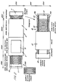
- a heating section generally indicated by A is provided and includes a continuously operating conveyor 1 onto which staves 10 which have been pre-cut to the desired shape and size can be loaded at one end.
- the staves are generally flat elongate pieces of wood with tapering ends. In cross-section the upper (inner) surface is slightly concave whilst the lower (outer) surface is slightly convex. The cross-sectional shape is necessary to form the bilge.
- the staves 10 are then transported by the conveyor 1 into a volumetric heating section 2 which provides volumetric heating by the application of radio frequency electromagnetic radiation.
- the volumetric heating section 2 comprises a radio frequency heating section in this embodiment and includes a matching box 3 and an RF electrode 4 which is suspended above the conveyor.
- the radiant heating section 5 comprises an array of infrared emitters 6 suspended above the conveyor 1 to thereby toast the upper (inner) surface of the cask staves 10 as they pass through the radiant heating section 5.
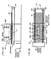
- the pressing section B comprises a conveyor arrangement 11 for conveying a plurality of parallel spaced heated staves 10 through the press arrangement 12.
- the conveyor arrangement 11 comprises two parallel chain conveyors 11a and 11b which support the staves 10 just inboard of their outer ends.
- the chain conveyors 11a and 11b carry locators 13 to position each stave 10 so that it is presented correctly to the press arrangement 12.
- the conveyor arrangement 11 conveys the staves 10 into the press arrangement 12.
- the press arrangement 12 comprises a male press part 14 comprising a plurality of male press faces 15.
- the male press part 14 is arranged to lie above the centre of a plurality (in the illustrated example 10) of staves 10.
- the male press part 14 is connected to and driven by two actuators 16a and 16b which can operate to force the male press member against the upper surfaces of the centre part of the staves 10 as shown in Figure 3a.
- the faces 15 of the press male part 14 have a convex surface in two orthogonal directions so that when they contact the upper surface of the centre portion of the staves 10 they tend to induce a curvature along the elongate axis of the staves 10 and fit into the concave shape of the upper (inner) surface of the stave without damaging its edges.
- a female press arrangement 17 which can be seen in Figure 3b as comprising two parallel bars 17a and 17b arranged at or near the ends of the staves 10.
- the actuators 16a and 16b force the male press part 14 against the upper surfaces of a plurality of staves 10, whereby the chain conveyors 11a and 11b are deflected such that the ends of the staves 10 come into contact with the female press arrangement 17 comprising the bars 17a and 17b. Further force by the actuators 16a and 16b causes the curving of the staves 10.
- the pressing section B also includes a hopper 18 to receive the formed staves. Alternatively the formed staves can be discharged into an assembly jig for the automatic forming of casks.
- Staves which have been pre-cut to the required shape and size from new wood are loaded onto the conveyor belt 1 of the heating section A and continually pass first through a radio frequency heated zone 2 where the temperature of the body of the stave 10 is raised to a predetermined temperature which is preferably in the order of 100°C to 140°C.
- a predetermined temperature which is preferably in the order of 100°C to 140°C.
- This heating process also makes the structure of the wood more pliable for later forming.
- the rate of temperature rise must be controlled to avoid damage to the structure of the wood and it has been found that three minutes is a satisfactory time in which to raise the temperature with minimum damage.
- heated air can be simultaneously applied in order to prevent heat loss from the surface of the staves 10.
- a convenient air temperature for this is in the region of 130°C.
- the stave blanks 10 are then carried into a surface toasting zone which is the radiant heating section 5 which can either be electrically or gas operated.
- the radiant heating section 5 what will become the inner cask surface is then heated using a high power density non-contact heating system which can conveniently be a medium wave electric or gas infrared heater with an emitter surface temperature in the range of 600°C to 900°C.
- the so-called “toasting" of the surface causes local changes to the wood chemistry manifest by a colour change.
- the degree of toasting is controlled by the duration of the heating to achieve the desired flavour and colour characteristics as specified by a distiller.
- the staves 10 Once the staves 10 have been heated in the two stages they can be transferred automatically or manually to the pressing section B, where by mechanical or hydraulical means the stave is formed to the desired shape whilst still hot.
- the staves 10 are transferred onto a conveyor arrangement 11 and are arranged to lie spaced and parallel with the toasted surface facing upwards. The staves 10 are then transferred into the press arrangement 12.
- a male press member 14 is forced onto the middle section of the toasted upper surface of the staves 10 whereby the conveyor arrangement 11 is deflected downwards until the staves 10 contact the female press arrangement 17.
- the female press arrangement 17 supports the ends of the staves and further application of force by the male press arrangement 14 causes the staves 10 to bend.
- casks are required to be watertight. To achieve this it is necessary that the formed staves offered up for assembly are slightly under bent so that the metal hoops can pull them to final shape during assembly. It is therefore important that the degree of over-bend and spring-back is controlled accordingly. Provision is made on the press to adjust the position of a stop on the closing stroke to achieve this.
- the water can be applied to the stave 10 in a number of ways including immersion, wiping and spraying. In the embodiment illustrated the preferred method is spraying.
- a typical cycle time of press closure, hold and press release is in the region of three minutes.
- the present invention is not limited to the combination of such features although a most useful method of forming cask staves for certain applications is achieved using the combination.
- the heating section A it is also within the scope of the present invention to only utilise the heating section A to provide cask staves which have been heat treated as desired for assembling into casks using traditional methods.
- the heating section A can be used to heat treat second hand staves which have become "exhausted" by earlier fills.
- the pressing section B is not required.
- each of the faces 15 of the male press part 14 may be provided with an individual actuator and each face 15 may be of a different shape i.e. curvature.
Landscapes
- Life Sciences & Earth Sciences (AREA)
- Engineering & Computer Science (AREA)
- Wood Science & Technology (AREA)
- Organic Chemistry (AREA)
- Chemical & Material Sciences (AREA)
- General Health & Medical Sciences (AREA)
- Bioinformatics & Cheminformatics (AREA)
- General Engineering & Computer Science (AREA)
- Biochemistry (AREA)
- Genetics & Genomics (AREA)
- Health & Medical Sciences (AREA)
- Zoology (AREA)
- Manufacturing & Machinery (AREA)
- Mechanical Engineering (AREA)
- Forests & Forestry (AREA)
- Chemical And Physical Treatments For Wood And The Like (AREA)
- Extrusion Moulding Of Plastics Or The Like (AREA)
Claims (30)
- Verfahren zum Herstellen von Faßdauben, umfassend die Schritte des Bereitstellens eines Daubenrohlings (10) der geforderten Form und Größe, sowie des volumetrischen Aufheizens des Daubenrohlings (10) derart, daß durch das Aufheizen herbeigeführte chemische Veränderungen im gesamten Daubenrohling gleichförmig sind.
- Verfahren nach Anspruch 1, wobei der Daubenrohling (10) unter Verwendung von elektromagnetischer Strahlung dielektrisch aufgeheizt wird.
- Verfahren nach Anspruch 2, wobei der Daubenrohling (10) unter Verwendung von Radiofrequenzstrahlung aufgeheizt wird.
- Verfahren nach Anspruch 2, wobei der Daubenrohling (10) unter Verwendung von Mikrowellenstrahlung aufgeheizt wird.
- Verfahren nach einem der vorhergehenden Ansprüche, umfassend den Schritt des Aufheizens einer Fläche des Daubenrohlings (10).
- Verfahren nach Anspruch 5, wobei die Fläche des Daubenrohlings (10) unter Verwendung von Strahlungswärme aufgeheizt wird.
- Verfahren nach einem der vorhergehenden Ansprüche, wobei der Schritt des volumetrischen Aufheizens die Temperatur des Daubenrohlings (10) gleichförmig auf zwischen 100°C und 140°C erhöht.
- Verfahren nach Anspruch 7, wobei die Temperatur des Daubenrohlings (10) auf zwischen 100°C und 140°C innerhalb einer Zeitskala von 2 Minuten oder mehr erhöht wird.
- Verfahren nach Anspruch 8, wobei die Zeitskala wenigstens 3 Minuten beträgt.
- Verfahren nach Anspruch 6, wobei die Strahlungswärme durch ein Strahlungsheizelement (6) bereitgestellt wird, welches in dem Bereich von 600° C bis 900° C betrieben wird und die Fläche nicht berührt.
- Verfahren nach einem der vorhergehenden Ansprüche, wobei der Schritt des volumentrischen Aufheizens den Schritt des Umwälzens von heißer Luft um den Daubenrohling (10) herum umfaßt.
- Verfahren nach Anspruch 11, wobei die Luft bei einer Temperatur von zwischen 100°C und 150°C umgewälzt wird.
- Verfahren nach einem der vorhergehenden Ansprüche, umfassend den Schritt des Pressens des aufgeheizten Daubenrohlings (10) während dieser noch heiß ist, um eine gewünschte Krümmung des aufgeheizten Daubenrohlings (10) zu erreichen.
- Verfahren nach Anspruch 13, wobei der Schritt des Pressens den Schritt des Anordnens des aufgeheizten Daubenrohlings (10) auf zwei Trägern (11a, 11b) umfaßt, derart, daß der aufgeheizte Daubenrohling (10) von seinen Enden ein wenig einwärts aufgenommen ist, sowie des Ausübens einer Kraft auf die Mitte des aufgeheizten Daubenrohlings (10), bis der gewünschte Grad der Krümmung erreicht ist.
- Verfahren nach Anspruch 13 oder 14, umfassend den Schritt des Aufbringens von Wasser auf eine zweite Fläche des aufgeheizten Daubenrohlings (10), welche der Fläche, die der Strahlungsheizung ausgesetzt wurde, entgegengesetzt ist.
- Verfahren nach Anspruch 15, wobei das Wasser durch Eintauchen, Wischen oder Sprühen aufgebracht wird.
- Verfahren nach einem der Ansprüche 13 bis 16, wobei der Schritt des Pressens zwischen 2 und 5 Minuten dauert.
- Verfahren nach einem der vorhergehenden Ansprüche, umfassend den Schritt des Schneidens des Daubenrohlings (10) der geforderten Form und Größe von einem gewünschten Holz.
- Vorrichtung zur Herstellung von Faßdauben, umfassend volumetrische Aufheizmittel (2) zum gleichförmigen Aufheizen eines Daubenrohlings (10) der geforderten Gestalt und Größe derart, daß im gesamten Daubenrohling (10) gleichförmige chemische Veränderungen stattfinden.
- Vorrichtung nach Anspruch 19, wobei die volumetrischen Aufheizmittel (2) dielektrische Aufheizmittel (4) zum dielektrischen Heizen des Daubenrohlings (10) unter Verwendung von elektromagnetischer Strahlung umfassen.
- Vorrichtung nach Anspruch 19 oder 20, wobei die dielektrischen Aufheizmittel (2) ein Radiofrequenzheizelement (4) umfassen.
- Vorrichtung nach Anspruch 19 oder 20, wobei die dielektrischen Aufheizmittel (2) ein Mikrowellenheizelement umfassen.
- Vorrichtung nach einem der Ansprüche 19 bis 22, umfassend ein Strahlungsheizelement (6) zum Aufheizen einer Fläche des Daubenrohlings (10).
- Vorrichtung nach einem der Ansprüche 19 bis 23, umfassend Heißluftumwälzmittel zum Umwälzen von heißer Luft um den Daubenrohling (10) herum während des volumetrischen Aufheizens.
- Vorrichtung nach einem der Ansprüche 19 bis 24, umfassend Fördermittel (1) zum kontinuierlichen Fördern einer Mehrzahl von Daubenrohlingen (10) durch die volumetrischen Aufheizmittel (2).
- Vorrichtung nach einem der Ansprüche 19 bis 25, umfassend eine Presse (12) zum Pressen des aufgeheizten Daubenrohlings (10), während dieser noch heiß ist, um die gewünschte Krümmung des aufgeheizten Daubenrohlings (10) zu erreichen.
- Vorrichtung nach Anspruch 26, umfassend ein zweites Fördermittel (11) zum Fördern einer Mehrzahl von aufgeheizten Daubenrohlingen (10) in die Presse (12), wobei die Presse (12) zum gleichzeitigen Pressen einer Mehrzahl von aufgeheizten Daubenrohlingen (10) ausgebildet ist.
- Vorrichtung nach Anspruch 27, wobei das zweite Fördermittel (11) zwei parallele Förderer (11a, 11b) umfaßt, welche angeordnet sind, um eine Mehrzahl von im wesentlichen parallelen, mit Abstand zueinander angeordneten aufgeheizten Daubenrohlingen (10) zu tragen.
- Vorrichtung nach Anspruch 28, wobei die Presse (2) ein männliches Teil (14) umfaßt, welches bewegbar ausgebildet ist, um eine Kraft auf die Mitte der aufgeheizten Daubenrohlinge (10) auf den Förderern (11a, 11b) auszuüben, sowie ein weibliches Teil (17) umfaßt, welches unter den Förderern (11a, 11b) angeordnet ist, um die aufgeheizten Daubenrohlinge (10) aufzunehmen, da die Förderer (11 a, 11b) durch die vom männlichen Teil (14) ausgeübte Kraft verlagert sind, wobei das weibliche Teil (17) angeordnet ist, um die aufgeheizten Daubenrohlinge (10) von deren Enden ein wenig einwärts zu stützen, während die Kraft durch das männliche Teil (14) auf die Mitte der aufgeheizten Daubenrohlinge (10) ausgeübt wird.
- Vorrichtung nach einem der Ansprüche 19 bis 29, umfassend Aufbringmittel zum Aufbringen von Wasser auf eine zweite Fläche des aufgeheizten Daubenrohlings (10), welche der Fläche entgegengesetzt ist, die der während des Pressens ausgeübten Kraft ausgesetzt ist.
Applications Claiming Priority (3)
| Application Number | Priority Date | Filing Date | Title |
|---|---|---|---|
| GB9501049A GB2297077B (en) | 1995-01-19 | 1995-01-19 | Method of manufacturing cask staves |
| GB9501049 | 1995-01-19 | ||
| PCT/GB1996/000084 WO1996022358A1 (en) | 1995-01-19 | 1996-01-17 | Apparatus for and method of manufacturing cask staves |
Publications (2)
| Publication Number | Publication Date |
|---|---|
| EP0805848A1 EP0805848A1 (de) | 1997-11-12 |
| EP0805848B1 true EP0805848B1 (de) | 2000-03-15 |
Family
ID=10768260
Family Applications (1)
| Application Number | Title | Priority Date | Filing Date |
|---|---|---|---|
| EP96900366A Expired - Lifetime EP0805848B1 (de) | 1995-01-19 | 1996-01-17 | Verfahren und vorrichtung zur herstellung von fassdauben |
Country Status (6)
| Country | Link |
|---|---|
| EP (1) | EP0805848B1 (de) |
| AU (1) | AU704316B2 (de) |
| DE (1) | DE69607144D1 (de) |
| ES (1) | ES2146381T3 (de) |
| GB (1) | GB2297077B (de) |
| WO (1) | WO1996022358A1 (de) |
Families Citing this family (2)
| Publication number | Priority date | Publication date | Assignee | Title |
|---|---|---|---|---|
| FR2907703B1 (fr) * | 2006-10-30 | 2008-12-19 | Patrick Lalanne | Procede de fabrication d'une barrique en bois, kit pour barrique, barrique obtenue. |
| US8381926B2 (en) | 2009-05-29 | 2013-02-26 | DBGlobal, LLC | Barrel construction |
Family Cites Families (9)
| Publication number | Priority date | Publication date | Assignee | Title |
|---|---|---|---|---|
| GB463135A (en) * | 1934-08-22 | 1937-03-22 | William Ralph Anderson | Improvements relating to a method and mechanism for bending barrel staves and making barrels therefrom |
| GB654785A (en) * | 1948-08-30 | 1951-06-27 | Arthur Cyril Merron | Improvements in the manufacture of barrels |
| US3842723A (en) * | 1969-02-10 | 1974-10-22 | Seagram & Sons Inc | Whiskey barrel |
| US4018642A (en) * | 1975-09-08 | 1977-04-19 | Macmillan Bloedel Limited | Microwave curing of alkaline phenolic resins in wood-resin compositions |
| SU630292A1 (ru) * | 1977-06-23 | 1978-10-30 | Московский ордена Трудового Красного Знамени технологический институт пищевой промышленности | Способ выделени дубильных веществ из древесины дуба при производстве крепких напитков |
| SU1196373A1 (ru) * | 1982-11-03 | 1985-12-07 | Московский ордена Трудового Красного Знамени технологический институт пищевой промышленности | Способ созревани крепких напитков |
| GB2163777B (en) * | 1984-08-31 | 1988-04-07 | Mo T I Pischevoi Promy | Process for maturing strong beverages |
| AU585065B2 (en) * | 1985-09-19 | 1989-06-08 | Douglas William Fulton | Method and apparatus for making barrels and casks |
| GB2281016A (en) * | 1993-08-10 | 1995-02-15 | Ea Tech Ltd | Microwave-assisted processing of materials |
-
1995
- 1995-01-19 GB GB9501049A patent/GB2297077B/en not_active Revoked
-
1996
- 1996-01-17 ES ES96900366T patent/ES2146381T3/es not_active Expired - Lifetime
- 1996-01-17 AU AU43962/96A patent/AU704316B2/en not_active Ceased
- 1996-01-17 EP EP96900366A patent/EP0805848B1/de not_active Expired - Lifetime
- 1996-01-17 WO PCT/GB1996/000084 patent/WO1996022358A1/en not_active Ceased
- 1996-01-17 DE DE69607144T patent/DE69607144D1/de not_active Expired - Lifetime
Also Published As
| Publication number | Publication date |
|---|---|
| ES2146381T3 (es) | 2000-08-01 |
| WO1996022358A1 (en) | 1996-07-25 |
| AU4396296A (en) | 1996-08-07 |
| DE69607144D1 (de) | 2000-04-20 |
| GB2297077A (en) | 1996-07-24 |
| AU704316B2 (en) | 1999-04-22 |
| GB2297077B (en) | 1999-03-10 |
| GB9501049D0 (en) | 1995-03-08 |
| EP0805848A1 (de) | 1997-11-12 |
Similar Documents
| Publication | Publication Date | Title |
|---|---|---|
| EP1308252B1 (de) | Verfahren und Vorrichtung zum Formen von Holzfaserplatten | |
| US6898834B1 (en) | Barrel stave reclaim | |
| EP0805848B1 (de) | Verfahren und vorrichtung zur herstellung von fassdauben | |
| EP0928587A1 (de) | Kochgerät mit einer Platinenabdeckung aus Stahl und Verfahren und Gerät zum Formen desselben | |
| US9610707B2 (en) | Method and device for the molding of wood fiber board | |
| CN110653573A (zh) | 三复合封头制作方法 | |
| US8038437B2 (en) | Method and device for heat treatment of wooden staves designed to form aromatic inserts | |
| JP5097604B2 (ja) | 木材の成形方法 | |
| KR20170100793A (ko) | 바닥의 내구성이 향상된 인덕션용 프라이팬 제조방법 및 그 방법에 의해 제조된 프라이팬 | |
| JP5248948B2 (ja) | 圧縮木製品の製造方法および圧縮木製品 | |
| US7179082B2 (en) | Process and apparatus for inner wall toasting of casks for wine guard by hot air convection | |
| KR102723961B1 (ko) | 균일 가열 가능한 조리용기 제조용 단조금형 | |
| AU737480B2 (en) | Process for coating and sublistatically printing ceramic articles | |
| JP5265469B2 (ja) | 木材成形用金型 | |
| JP2009255345A (ja) | 木材の成形方法 | |
| JPH04164603A (ja) | 弯曲集成板の製造方法 | |
| GB2309402A (en) | Container handles | |
| JP2011011444A (ja) | 圧縮用木材および木材の成形方法 | |
| JP2005041121A (ja) | 木製トレー製造用金型 |
Legal Events
| Date | Code | Title | Description |
|---|---|---|---|
| PUAI | Public reference made under article 153(3) epc to a published international application that has entered the european phase |
Free format text: ORIGINAL CODE: 0009012 |
|
| 17P | Request for examination filed |
Effective date: 19970703 |
|
| AK | Designated contracting states |
Kind code of ref document: A1 Designated state(s): DE ES FR GB IT |
|
| 17Q | First examination report despatched |
Effective date: 19981208 |
|
| GRAG | Despatch of communication of intention to grant |
Free format text: ORIGINAL CODE: EPIDOS AGRA |
|
| GRAG | Despatch of communication of intention to grant |
Free format text: ORIGINAL CODE: EPIDOS AGRA |
|
| GRAG | Despatch of communication of intention to grant |
Free format text: ORIGINAL CODE: EPIDOS AGRA |
|
| GRAH | Despatch of communication of intention to grant a patent |
Free format text: ORIGINAL CODE: EPIDOS IGRA |
|
| GRAH | Despatch of communication of intention to grant a patent |
Free format text: ORIGINAL CODE: EPIDOS IGRA |
|
| GRAA | (expected) grant |
Free format text: ORIGINAL CODE: 0009210 |
|
| AK | Designated contracting states |
Kind code of ref document: B1 Designated state(s): DE ES FR GB IT |
|
| REF | Corresponds to: |
Ref document number: 69607144 Country of ref document: DE Date of ref document: 20000420 |
|
| ET | Fr: translation filed | ||
| RAP2 | Party data changed (patent owner data changed or rights of a patent transferred) |
Owner name: SCOTTISH AND SOUTHERN ENERGY PLC |
|
| ITF | It: translation for a ep patent filed | ||
| PG25 | Lapsed in a contracting state [announced via postgrant information from national office to epo] |
Ref country code: DE Free format text: LAPSE BECAUSE OF FAILURE TO SUBMIT A TRANSLATION OF THE DESCRIPTION OR TO PAY THE FEE WITHIN THE PRESCRIBED TIME-LIMIT Effective date: 20000616 |
|
| REG | Reference to a national code |
Ref country code: ES Ref legal event code: FG2A Ref document number: 2146381 Country of ref document: ES Kind code of ref document: T3 |
|
| PGFP | Annual fee paid to national office [announced via postgrant information from national office to epo] |
Ref country code: FR Payment date: 20001128 Year of fee payment: 6 |
|
| PGFP | Annual fee paid to national office [announced via postgrant information from national office to epo] |
Ref country code: ES Payment date: 20010108 Year of fee payment: 6 |
|
| PLBE | No opposition filed within time limit |
Free format text: ORIGINAL CODE: 0009261 |
|
| STAA | Information on the status of an ep patent application or granted ep patent |
Free format text: STATUS: NO OPPOSITION FILED WITHIN TIME LIMIT |
|
| 26N | No opposition filed | ||
| REG | Reference to a national code |
Ref country code: GB Ref legal event code: IF02 |
|
| PGFP | Annual fee paid to national office [announced via postgrant information from national office to epo] |
Ref country code: GB Payment date: 20020327 Year of fee payment: 7 |
|
| PG25 | Lapsed in a contracting state [announced via postgrant information from national office to epo] |
Ref country code: GB Free format text: LAPSE BECAUSE OF NON-PAYMENT OF DUE FEES Effective date: 20030117 |
|
| GBPC | Gb: european patent ceased through non-payment of renewal fee | ||
| PG25 | Lapsed in a contracting state [announced via postgrant information from national office to epo] |
Ref country code: FR Free format text: LAPSE BECAUSE OF NON-PAYMENT OF DUE FEES Effective date: 20030930 |
|
| REG | Reference to a national code |
Ref country code: FR Ref legal event code: ST |
|
| PG25 | Lapsed in a contracting state [announced via postgrant information from national office to epo] |
Ref country code: ES Free format text: LAPSE BECAUSE OF NON-PAYMENT OF DUE FEES Effective date: 20031122 |
|
| REG | Reference to a national code |
Ref country code: ES Ref legal event code: FD2A Effective date: 20031122 |
|
| PG25 | Lapsed in a contracting state [announced via postgrant information from national office to epo] |
Ref country code: IT Free format text: LAPSE BECAUSE OF NON-PAYMENT OF DUE FEES Effective date: 20050117 |
|
| PG25 | Lapsed in a contracting state [announced via postgrant information from national office to epo] |
Ref country code: FR Free format text: LAPSE BECAUSE OF NON-PAYMENT OF DUE FEES Effective date: 20020131 |
|
| PG25 | Lapsed in a contracting state [announced via postgrant information from national office to epo] |
Ref country code: ES Free format text: LAPSE BECAUSE OF NON-PAYMENT OF DUE FEES Effective date: 20020131 |