EP0805543B1 - Elektromotor - Google Patents
Elektromotor Download PDFInfo
- Publication number
- EP0805543B1 EP0805543B1 EP97107063A EP97107063A EP0805543B1 EP 0805543 B1 EP0805543 B1 EP 0805543B1 EP 97107063 A EP97107063 A EP 97107063A EP 97107063 A EP97107063 A EP 97107063A EP 0805543 B1 EP0805543 B1 EP 0805543B1
- Authority
- EP
- European Patent Office
- Prior art keywords
- motor according
- shaft
- rotor shaft
- rotor
- spring element
- Prior art date
- Legal status (The legal status is an assumption and is not a legal conclusion. Google has not performed a legal analysis and makes no representation as to the accuracy of the status listed.)
- Expired - Lifetime
Links
- 239000004033 plastic Substances 0.000 claims abstract description 7
- 239000002184 metal Substances 0.000 claims abstract description 4
- 239000004952 Polyamide Substances 0.000 claims abstract description 3
- 229920002647 polyamide Polymers 0.000 claims abstract description 3
- 239000004810 polytetrafluoroethylene Substances 0.000 claims abstract description 3
- 229920001343 polytetrafluoroethylene Polymers 0.000 claims abstract description 3
- 230000005291 magnetic effect Effects 0.000 claims description 17
- 230000035699 permeability Effects 0.000 claims description 6
- 238000005299 abrasion Methods 0.000 claims description 2
- 230000037431 insertion Effects 0.000 claims 1
- 238000003780 insertion Methods 0.000 claims 1
- 238000011161 development Methods 0.000 description 3
- 230000018109 developmental process Effects 0.000 description 3
- 238000004804 winding Methods 0.000 description 3
- 230000000694 effects Effects 0.000 description 2
- 229910000897 Babbitt (metal) Inorganic materials 0.000 description 1
- 208000019300 CLIPPERS Diseases 0.000 description 1
- 208000021930 chronic lymphocytic inflammation with pontine perivascular enhancement responsive to steroids Diseases 0.000 description 1
- 230000001419 dependent effect Effects 0.000 description 1
- 239000003302 ferromagnetic material Substances 0.000 description 1
- 239000000314 lubricant Substances 0.000 description 1
- 239000000463 material Substances 0.000 description 1
- 230000036316 preload Effects 0.000 description 1
Images
Classifications
-
- H—ELECTRICITY
- H02—GENERATION; CONVERSION OR DISTRIBUTION OF ELECTRIC POWER
- H02K—DYNAMO-ELECTRIC MACHINES
- H02K5/00—Casings; Enclosures; Supports
- H02K5/04—Casings or enclosures characterised by the shape, form or construction thereof
- H02K5/16—Means for supporting bearings, e.g. insulating supports or means for fitting bearings in the bearing-shields
- H02K5/167—Means for supporting bearings, e.g. insulating supports or means for fitting bearings in the bearing-shields using sliding-contact or spherical cap bearings
- H02K5/1672—Means for supporting bearings, e.g. insulating supports or means for fitting bearings in the bearing-shields using sliding-contact or spherical cap bearings radially supporting the rotary shaft at both ends of the rotor
Definitions
- the invention relates to an electric motor with a housing which accommodates a stator in which a rotor is rotatably arranged with a rotor shaft, and with bearings arranged on the end side for the rotor shaft.
- electric motors in a motor housing have a stationary, housing-fixed stator and a rotor rotatable therein.
- the rotor is in this case arranged on a rotor shaft, which in turn is mounted in arranged on both end sides of the motor housing, so-called end shields.
- end shields For the power supply of the stator winding and arranged on the rotor rotor winding, in which an opposing field is generated, further terminals are provided, which are each connected to the associated windings.
- a major cause of this noise is the bearing for the rotor shaft, which is guided in the bearings provided in the end shields.
- the shafts are fitted with the prescribed tolerance in the bearings, but cause tolerances, the surface condition of the rotor and its deviation from the straightness, that is the deviation of its geometry from the specifications, to corresponding imbalances, in turn, on the bearings impact loads. It has been shown that, especially in radial bearing loads, as they occur when using the engine as an eccentric, for example, in razors, hair trimmers and the like., The emanating from the camps noise is significantly increased.
- the rotor shaft is selectively acted on one side of a radially directed force at one of its two ends.
- the mentioned fit clearance between the rotor shaft and the bearing or between the rotor shaft and the housing is minimized by the shaft is deflected laterally with respect to its longitudinal axis by the amount of the existing matching game and thus a certain Preload is subject to, which is suppressed without such measures from the bearing clearance or the match clearance noise.
- thereby caused braking effects for the rotor shaft are negligible.
- a spring element is provided for applying the radial force, which exerts the radially directed force on one side on one end of the rotor shaft.
- the spring element may be made of metal or plastic.
- the required deflection forces are so low that the use of plastic springs is considered unproblematic.
- a leaf spring is provided as a spring element, which is clamped on the housing and applies with the required bias against the intended shaft end.
- the spring element indirectly acts on the end of the rotor shaft, namely with the interposition of a pressure piece.
- Such a pressure piece which serves in particular to ensure the radial as well as possibly the axial guidance of the rotor shaft by being adapted to the wave contour can advantageously consist of abrasion-resistant plastic, in particular of PTFE or polyamide, but also of a metal body, for Example with a bearing made of bearing metal.
- the pressure piece has a felt support which cooperates directly with the rotor shaft.
- This felt pad is advantageously soaked with a lubricious lubricant to minimize frictional resistance.
- a further embodiment provides that the spring element provided for noise reduction acts on the bearing associated with the relevant shaft end. This solution has the advantage that the mentioned friction forces are kept as low as possible and the frictional wear on the shaft or on the spring element is avoided.
- the rotor shaft at the respective end has a permeability ⁇ R > 1, preferably a permeability ⁇ R >> 1, and that this shaft end targeted on one side radially with magnetic force is charged.
- the invention makes use of the fact that the rotor shafts of electric motors as well as the rotors themselves are usually made of ferromagnetic materials.
- the shaft material has a permeability ⁇ R ⁇ 1 that the magnet shaft acted upon shaft end of the rotor shaft is provided with an additional part which has a permeability ⁇ R > 1 and the load from the absorbed magnetic force on the shaft end transfers.
- the respective end of the shaft can be associated with a magnet having a magnetic field directed radially on one side radially on the shaft end, which supplies the magnetic force required for suppressing the noise-favorable matching clearance.
- the magnet may be formed as a permanent magnet or as an electromagnet.
- the inventive device for noise reduction is basically suitable for all electric motors, but the application of the invention is particularly intended for small and micro motors, as they are commonly used as drive motors for the mentioned electric shavers, hair clippers and similar high-speed electrical equipment, in which a high noise level is distracting.
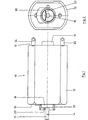
- Fig. 1 is an inventive electric motor 10 is shown with a housing 12 in side view.
- the electric motor 10 has, like all such motors, a stator and a rotor, which are covered in this view by the outer wall of the housing 12, and a rotor shaft 14, with which the rotor is connected and at the in Fig. 1 left end face 16 of the housing 12 is mounted in a first bearing 18 and from which a shaft end 15 protrudes.
- the first bearing 18 cooperates with a spring device 20, which surrounds the bearing 18 in a ring-like manner and acts on the front-side outer surface directly exiting the here emerging shaft end of the rotor shaft 14 with a leaf spring 22 on one side radially.
- a spring device 20 which surrounds the bearing 18 in a ring-like manner and acts on the front-side outer surface directly exiting the here emerging shaft end of the rotor shaft 14 with a leaf spring 22 on one side radially.
- a bearing plate 19 is provided with a further bearing in which the associated end of the rotor shaft 14 is mounted.
- terminal contacts 24, 25 are arranged for the electrical power supply of the motor 10 at this end face.
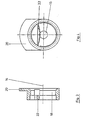
- Fig. 2 is the view of the provided with the spring device 20 end face of the motor 10 reproduced, from which it can be seen how the leaf spring 22 is applied virtually tangentially to the rotor shaft 14.
- Fig. 3 is a longitudinal section through the spring device 20 described above, which surrounds the support bearing 18 for the rotor shaft 14 in the installed state, shown on an enlarged scale. It can be seen clearly that the leaf spring 22 of the spring device 20 has a curved toward the shaft 14 outward contour to keep the contact surface with the rotor shaft 14 as small as possible and thus to minimize the resulting friction losses.
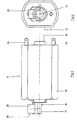
- Fig. 5 is also an inventive electric motor 11 with a housing 12 in side view shown.
- the electric motor 10 also has a stator and a rotor and a rotor shaft 14, with which the rotor is connected and which are connected to the in Fig. 4 left end face 16 of the housing 12 is mounted in a first bearing 18 and from which a shaft end 15 protrudes.
- the first bearing 18 cooperates with a magnetic device 26 which surrounds the bearing 18 in an annular manner and acts on the frontal outer surface directly exiting the here emerging shaft end of the rotor shaft 14 with a magnet 28 on one side radially directed.
- a magnetic device 26 which surrounds the bearing 18 in an annular manner and acts on the frontal outer surface directly exiting the here emerging shaft end of the rotor shaft 14 with a magnet 28 on one side radially directed.
- the rotor shaft 14 is acted upon by the existing clearance play in the direction away from the magnet 28, whereby the existing match play is compensated and possible noise developments caused by the matching play are suppressed.
- a bearing plate 19 is provided with a further bearing in which the associated end of the rotor shaft 14 is mounted.
- terminal contacts 24, 25 are arranged for the electrical power supply of the motor 10 at this end face.
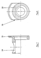
- Fig. 6 is the view of the provided with the magnetic device 26 end face of the motor 11 reproduced, from which it can be seen how the magnet 28 is arranged quasi-tangentially at a distance from the rotor shaft 14 and this applied to its magnetic field.
- Fig. 7 is a longitudinal section through the previously described magnetic device 26, which surrounds the support bearing 18 for the rotor shaft 14 in the installed state, shown in an enlarged scale. This is clear to recognize that the magnet 28 of the magnetic device 26 has a distance from the shaft 14 and in this way avoids any frictional contact with the rotor shaft 14.
Landscapes
- Engineering & Computer Science (AREA)
- Power Engineering (AREA)
- Motor Or Generator Frames (AREA)
- Valve Device For Special Equipments (AREA)
- Transition And Organic Metals Composition Catalysts For Addition Polymerization (AREA)
- Glass Compositions (AREA)
- Connection Of Motors, Electrical Generators, Mechanical Devices, And The Like (AREA)
- Iron Core Of Rotating Electric Machines (AREA)
Applications Claiming Priority (2)
| Application Number | Priority Date | Filing Date | Title |
|---|---|---|---|
| DE19617448 | 1996-05-02 | ||
| DE19617448A DE19617448A1 (de) | 1996-05-02 | 1996-05-02 | Elektromotor |
Publications (3)
| Publication Number | Publication Date |
|---|---|
| EP0805543A2 EP0805543A2 (de) | 1997-11-05 |
| EP0805543A3 EP0805543A3 (de) | 2000-08-30 |
| EP0805543B1 true EP0805543B1 (de) | 2009-07-01 |
Family
ID=7792996
Family Applications (1)
| Application Number | Title | Priority Date | Filing Date |
|---|---|---|---|
| EP97107063A Expired - Lifetime EP0805543B1 (de) | 1996-05-02 | 1997-04-29 | Elektromotor |
Country Status (5)
| Country | Link |
|---|---|
| EP (1) | EP0805543B1 (ja) |
| JP (1) | JPH1051992A (ja) |
| AT (1) | ATE435514T1 (ja) |
| DE (2) | DE19617448A1 (ja) |
| ES (1) | ES2328090T3 (ja) |
Families Citing this family (6)
| Publication number | Priority date | Publication date | Assignee | Title |
|---|---|---|---|---|
| DE19854535A1 (de) | 1998-11-26 | 2000-06-15 | Valeo Auto Electric Gmbh | Antriebsvorrichtung, insbesondere für eine Scheibenwischanlage eines Kraftfahrzeugs |
| US6739053B2 (en) | 2000-12-14 | 2004-05-25 | Wahl Clipper Corporation | Hair clipping device with internal vacuum |
| US6684511B2 (en) | 2000-12-14 | 2004-02-03 | Wahl Clipper Corporation | Hair clipping device with rotating bladeset having multiple cutting edges |
| DE10145558B4 (de) * | 2001-09-14 | 2006-05-18 | Bühler Motor GmbH | Stellantrieb, insbesondere für einen Schwenkantrieb in oder an Kraftfahrzeugen |
| JP2006014578A (ja) * | 2004-05-24 | 2006-01-12 | Minebea Co Ltd | ステッピングモータ |
| US8844142B2 (en) | 2011-03-18 | 2014-09-30 | Spectrum Brands, Inc. | Adjustable comb assembly for hair cutting appliance |
Citations (3)
| Publication number | Priority date | Publication date | Assignee | Title |
|---|---|---|---|---|
| JPS6318949A (ja) * | 1986-07-09 | 1988-01-26 | Matsushita Electric Ind Co Ltd | 小型モ−タの振動防止装置 |
| JPH01283041A (ja) * | 1988-05-06 | 1989-11-14 | Mitsubishi Electric Corp | モータ軸の振動抑制装置 |
| JPH08140306A (ja) * | 1994-11-11 | 1996-05-31 | Tokyo Parts Ind Co Ltd | ギヤードアクチュエーター |
Family Cites Families (10)
| Publication number | Priority date | Publication date | Assignee | Title |
|---|---|---|---|---|
| DE7116069U (de) * | 1971-04-26 | 1972-01-05 | Gebhardt W Kg | Achsenlagerung von Antriebsaggregaten |
| US4079274A (en) * | 1976-11-17 | 1978-03-14 | General Time Corporation | Damping of noise |
| DE2711560A1 (de) * | 1977-03-17 | 1978-09-21 | Weiss Paul Fa | Wellenlager fuer gleichstrom-kleinmotore |
| CH621456B (de) * | 1977-08-31 | Sodeco Compteurs De Geneve | Kleinsynchronmotor. | |
| DE3336385A1 (de) * | 1983-10-06 | 1985-04-25 | Philips Patentverwaltung Gmbh, 2000 Hamburg | Antriebsvorrichtung mit einem einphasensynchronmotor |
| DE3543544A1 (de) * | 1985-12-10 | 1987-06-11 | Bosch Gmbh Robert | Vorrichtung zur lueftergeraeuschminderung und -daempfung bei drehstromgeneratoren |
| NL8800914A (nl) * | 1988-04-08 | 1989-11-01 | Unihef Automobiel Bv | Voertuig met op en neer beweegbare laadvloer. |
| US5355042A (en) * | 1988-09-09 | 1994-10-11 | University Of Virginia Patent Foundation | Magnetic bearings for pumps, compressors and other rotating machinery |
| DE3840587C1 (en) * | 1988-12-02 | 1989-12-28 | Elektromotoren Werke Karl Kaiser Gmbh & Co, 2350 Neumuenster, De | Drawing-roller drive |
| DE69306422T2 (de) * | 1992-01-24 | 1997-06-05 | Philips Electronics Nv | Getriebe mit veränderlicher mechanischer Vorspannung |
-
1996
- 1996-05-02 DE DE19617448A patent/DE19617448A1/de not_active Withdrawn
-
1997
- 1997-04-29 AT AT97107063T patent/ATE435514T1/de not_active IP Right Cessation
- 1997-04-29 EP EP97107063A patent/EP0805543B1/de not_active Expired - Lifetime
- 1997-04-29 DE DE59713012T patent/DE59713012D1/de not_active Expired - Lifetime
- 1997-04-29 ES ES97107063T patent/ES2328090T3/es not_active Expired - Lifetime
- 1997-05-02 JP JP9114750A patent/JPH1051992A/ja active Pending
Patent Citations (3)
| Publication number | Priority date | Publication date | Assignee | Title |
|---|---|---|---|---|
| JPS6318949A (ja) * | 1986-07-09 | 1988-01-26 | Matsushita Electric Ind Co Ltd | 小型モ−タの振動防止装置 |
| JPH01283041A (ja) * | 1988-05-06 | 1989-11-14 | Mitsubishi Electric Corp | モータ軸の振動抑制装置 |
| JPH08140306A (ja) * | 1994-11-11 | 1996-05-31 | Tokyo Parts Ind Co Ltd | ギヤードアクチュエーター |
Also Published As
| Publication number | Publication date |
|---|---|
| EP0805543A2 (de) | 1997-11-05 |
| DE59713012D1 (de) | 2009-08-13 |
| EP0805543A3 (de) | 2000-08-30 |
| JPH1051992A (ja) | 1998-02-20 |
| ATE435514T1 (de) | 2009-07-15 |
| DE19617448A1 (de) | 1997-11-13 |
| ES2328090T3 (es) | 2009-11-06 |
Similar Documents
| Publication | Publication Date | Title |
|---|---|---|
| DE60023782T2 (de) | Kleinstmotor und sein Herstellungsverfahren | |
| EP1584130A1 (de) | Vorgespannte lagerung für elektrische maschinen | |
| EP0563583A1 (de) | Motorantrieb,insbesondere elektromotorischer Fenster- oder Schiebedachantrieb | |
| DE29513700U1 (de) | Motor-Getriebe-Antriebseinheit, insbesondere für einen Kraftfahrzeug-Fensterheberantrieb o.dgl. | |
| EP1609228A1 (de) | Elektrische maschine mit in den stator integrierter rotorlagerung | |
| EP1722459B1 (de) | Elektrische Maschine mit Abstützung des Rotors auf einer Stirnseite des Stators | |
| EP0805543B1 (de) | Elektromotor | |
| WO2000044082A1 (de) | Scheibenläufermotor mit lagervorspannung | |
| EP0222312A1 (de) | Federdruckbremse | |
| DE10160847A1 (de) | Betätigungsvorrichtung, insbesondere zur Betätigung von Sperrdifferentialen von Fahrzeugen | |
| DE102021109498A1 (de) | AUßENLÄUFERMOTOR | |
| EP4210206A1 (de) | Elektromotor zum antrieb einer fahrzeugklappe, verwendung und verfahren zur herstellung des elektromotors | |
| DE102021109493A1 (de) | AUßENLÄUFERMOTOR MIT KRAFTÜBERTRAGUNGSABSCHNITT | |
| DE3534381C2 (ja) | ||
| DE29624386U1 (de) | Elektromotor | |
| DE10018626A1 (de) | Rotor-Kräfteausgleichsstruktur | |
| DE102015207358A1 (de) | Elektrische Maschine und Lagerschild | |
| DE4206761C2 (de) | Lageranordnung für Rotoren elektrischer Maschinen | |
| EP0168744A2 (de) | Lagerschild für Gleichstrom-Kleinstmotoren | |
| EP0410488B1 (de) | Antriebseinheit mit einem Elektromotor | |
| DE3721757C2 (ja) | ||
| DE102004044340A1 (de) | Anlaufscheibe für eine elektrische Maschine | |
| WO2009049807A1 (de) | Elektromotor zur verwendung in einem zahnärztlichen, zahnmedizinischen oder dentaltechnischen handstück | |
| DE102016107855B4 (de) | Seitenkanalgebläse, insbesondere für ein Fahrzeugheizgerät | |
| WO2004040735A1 (de) | Antriebsvorrichtung |
Legal Events
| Date | Code | Title | Description |
|---|---|---|---|
| PUAI | Public reference made under article 153(3) epc to a published international application that has entered the european phase |
Free format text: ORIGINAL CODE: 0009012 |
|
| AK | Designated contracting states |
Kind code of ref document: A2 Designated state(s): AT CH DE ES FR GB IT LI NL |
|
| PUAL | Search report despatched |
Free format text: ORIGINAL CODE: 0009013 |
|
| AK | Designated contracting states |
Kind code of ref document: A3 Designated state(s): AT CH DE ES FR GB IT LI NL |
|
| 17P | Request for examination filed |
Effective date: 20001026 |
|
| RAP1 | Party data changed (applicant data changed or rights of an application transferred) |
Owner name: WAHL GMBH |
|
| 17Q | First examination report despatched |
Effective date: 20041011 |
|
| GRAP | Despatch of communication of intention to grant a patent |
Free format text: ORIGINAL CODE: EPIDOSNIGR1 |
|
| GRAS | Grant fee paid |
Free format text: ORIGINAL CODE: EPIDOSNIGR3 |
|
| GRAA | (expected) grant |
Free format text: ORIGINAL CODE: 0009210 |
|
| AK | Designated contracting states |
Kind code of ref document: B1 Designated state(s): AT CH DE ES FR GB IT LI NL |
|
| REG | Reference to a national code |
Ref country code: GB Ref legal event code: FG4D Free format text: NOT ENGLISH |
|
| REG | Reference to a national code |
Ref country code: CH Ref legal event code: EP |
|
| REF | Corresponds to: |
Ref document number: 59713012 Country of ref document: DE Date of ref document: 20090813 Kind code of ref document: P |
|
| REG | Reference to a national code |
Ref country code: ES Ref legal event code: FG2A Ref document number: 2328090 Country of ref document: ES Kind code of ref document: T3 |
|
| PLBE | No opposition filed within time limit |
Free format text: ORIGINAL CODE: 0009261 |
|
| STAA | Information on the status of an ep patent application or granted ep patent |
Free format text: STATUS: NO OPPOSITION FILED WITHIN TIME LIMIT |
|
| 26N | No opposition filed |
Effective date: 20100406 |
|
| REG | Reference to a national code |
Ref country code: CH Ref legal event code: PL |
|
| PG25 | Lapsed in a contracting state [announced via postgrant information from national office to epo] |
Ref country code: LI Free format text: LAPSE BECAUSE OF NON-PAYMENT OF DUE FEES Effective date: 20100430 Ref country code: CH Free format text: LAPSE BECAUSE OF NON-PAYMENT OF DUE FEES Effective date: 20100430 |
|
| PG25 | Lapsed in a contracting state [announced via postgrant information from national office to epo] |
Ref country code: AT Free format text: LAPSE BECAUSE OF NON-PAYMENT OF DUE FEES Effective date: 20100429 |
|
| REG | Reference to a national code |
Ref country code: FR Ref legal event code: PLFP Year of fee payment: 19 |
|
| PGFP | Annual fee paid to national office [announced via postgrant information from national office to epo] |
Ref country code: NL Payment date: 20150422 Year of fee payment: 19 |
|
| PGFP | Annual fee paid to national office [announced via postgrant information from national office to epo] |
Ref country code: GB Payment date: 20150423 Year of fee payment: 19 Ref country code: DE Payment date: 20150521 Year of fee payment: 19 Ref country code: ES Payment date: 20150427 Year of fee payment: 19 |
|
| PGFP | Annual fee paid to national office [announced via postgrant information from national office to epo] |
Ref country code: FR Payment date: 20150422 Year of fee payment: 19 Ref country code: IT Payment date: 20150427 Year of fee payment: 19 |
|
| REG | Reference to a national code |
Ref country code: DE Ref legal event code: R119 Ref document number: 59713012 Country of ref document: DE |
|
| REG | Reference to a national code |
Ref country code: NL Ref legal event code: MM Effective date: 20160501 |
|
| GBPC | Gb: european patent ceased through non-payment of renewal fee |
Effective date: 20160429 |
|
| REG | Reference to a national code |
Ref country code: FR Ref legal event code: ST Effective date: 20161230 |
|
| PG25 | Lapsed in a contracting state [announced via postgrant information from national office to epo] |
Ref country code: GB Free format text: LAPSE BECAUSE OF NON-PAYMENT OF DUE FEES Effective date: 20160429 Ref country code: DE Free format text: LAPSE BECAUSE OF NON-PAYMENT OF DUE FEES Effective date: 20161101 Ref country code: FR Free format text: LAPSE BECAUSE OF NON-PAYMENT OF DUE FEES Effective date: 20160502 Ref country code: NL Free format text: LAPSE BECAUSE OF NON-PAYMENT OF DUE FEES Effective date: 20160501 |
|
| PG25 | Lapsed in a contracting state [announced via postgrant information from national office to epo] |
Ref country code: IT Free format text: LAPSE BECAUSE OF NON-PAYMENT OF DUE FEES Effective date: 20160429 |
|
| REG | Reference to a national code |
Ref country code: ES Ref legal event code: FD2A Effective date: 20180507 |
|
| PG25 | Lapsed in a contracting state [announced via postgrant information from national office to epo] |
Ref country code: ES Free format text: LAPSE BECAUSE OF NON-PAYMENT OF DUE FEES Effective date: 20160430 |