EP0805543A2 - Elektromotor - Google Patents
Elektromotor Download PDFInfo
- Publication number
- EP0805543A2 EP0805543A2 EP97107063A EP97107063A EP0805543A2 EP 0805543 A2 EP0805543 A2 EP 0805543A2 EP 97107063 A EP97107063 A EP 97107063A EP 97107063 A EP97107063 A EP 97107063A EP 0805543 A2 EP0805543 A2 EP 0805543A2
- Authority
- EP
- European Patent Office
- Prior art keywords
- motor according
- shaft
- shaft end
- rotor shaft
- rotor
- Prior art date
- Legal status (The legal status is an assumption and is not a legal conclusion. Google has not performed a legal analysis and makes no representation as to the accuracy of the status listed.)
- Granted
Links
Images

Classifications
-
- H—ELECTRICITY
- H02—GENERATION; CONVERSION OR DISTRIBUTION OF ELECTRIC POWER
- H02K—DYNAMO-ELECTRIC MACHINES
- H02K5/00—Casings; Enclosures; Supports
- H02K5/04—Casings or enclosures characterised by the shape, form or construction thereof
- H02K5/16—Means for supporting bearings, e.g. insulating supports or means for fitting bearings in the bearing-shields
- H02K5/167—Means for supporting bearings, e.g. insulating supports or means for fitting bearings in the bearing-shields using sliding-contact or spherical cap bearings
- H02K5/1672—Means for supporting bearings, e.g. insulating supports or means for fitting bearings in the bearing-shields using sliding-contact or spherical cap bearings radially supporting the rotary shaft at both ends of the rotor
Definitions
- the invention relates to an electric motor with a housing that receives a stator, in which a rotor is rotatably arranged with a rotor shaft, and with bearings for the rotor shaft arranged on the end face.
- electric motors in a motor housing have a stationary, housing-fixed stator and a rotor rotatable therein.
- the rotor is arranged on a rotor shaft, which in turn is mounted in so-called end shields arranged on both ends of the motor housing.
- end shields arranged on both ends of the motor housing.
- connecting terminals are also provided, which are each connected to the assigned windings.
- a major cause of this noise development is the bearing for the rotor shaft, which is guided in the bearings provided in the end shields.
- the shafts are fitted into the bearing with the prescribed tolerance, but tolerances, the surface properties of the rotor and its deviation from the straightness, i.e. the deviation of its geometry from the specifications, lead to corresponding imbalances, which in turn affect those from the bearing impact loads. It has been shown that, particularly in the case of radial bearing loads such as occur when the motor is used as an eccentric drive, for example in razors, hair clippers and the like, the noise generated by the bearings is significantly increased.
- the rotor shaft is selectively acted upon on one side by a radially directed force at one of its two ends. This minimizes the mentioned clearance between the rotor shaft and the bearing or between the rotor shaft and the housing, in that the shaft is laterally deflected with respect to its longitudinal axis by the amount of the clearance clearance present and thus to a certain extent
- Bias is subject, whereby a noise development resulting from the bearing play or the fit play is suppressed without such measures. Fundamentally possible braking effects for the rotor shaft caused thereby are negligible.
- a spring element is provided for applying the radial force, which exerts the radially directed force on one side on one end of the rotor shaft.
- the spring element can consist of metal or plastic.
- the required deflection forces are so low that the use of plastic springs can be regarded as unproblematic.
- a leaf spring is provided as the spring element, which is clamped to the housing and bears against the intended shaft end with the required pretension.
- the spring element acts on the end of the rotor shaft indirectly, namely with the interposition of a pressure piece.
- Such a pressure piece which is used in particular to ensure the radial and optionally the axial guidance of the rotor shaft by adapting the shaft contour, can advantageously consist of abrasion-resistant plastic, in particular of PTFE or polyamide, but also of a metal body for Example with a bearing made of bearing metal.
- the pressure piece has a felt pad that works directly with the rotor shaft.
- This felt pad is advantageously impregnated with an easy-to-slide lubricant in order to minimize the frictional resistance.
- a further embodiment provides that the spring element provided for noise reduction acts on the bearing assigned to the relevant shaft end.
- This solution has the advantage that the friction forces mentioned are kept as low as possible and the frictional wear on the shaft or on the spring element is avoided.
- the rotor shaft at the respective end ⁇ a permeability R> has from 1, preferably a permeability ⁇ R >> 1, and that this shaft end targeted one side radially with magnetic force is acted upon.
- the invention makes use of the fact that the rotor shafts of electric motors as well as the rotors themselves are usually made of ferromagnetic materials.
- the shaft material has a permeability ⁇ R ⁇ 1
- the shaft end of the rotor shaft which is subjected to magnetic force is provided with an additional part which has a permeability ⁇ R > 1 and the load from the magnetic force absorbed on the shaft end transmits.
- a magnet with a magnetic field directed radially onto the shaft end on one side can be assigned to the shaft end in question, which magnetic field supplies the magnetic force required to suppress the noise-promoting clearance.
- the magnet can be designed as a permanent magnet or as an electromagnet.
- the device according to the invention for noise reduction is fundamentally suitable for all electric motors
- the application of the invention is particularly intended for small and very small motors, as are usually used as drive motors for the mentioned electric shavers, hair clippers and similar high-speed electrical devices in which a high noise level is perceived as annoying.
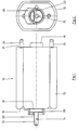
- FIG 1 shows an electric motor 10 according to the invention with a housing 12 in a side view.
- the electric motor 10 has a stator and a rotor, which in this view are covered by the outer wall of the housing 12, and a rotor shaft 14, to which the rotor is connected and which on the left-hand end face 16 of FIG Housing 12 is mounted in a first bearing 18 and from which a shaft end 15 protrudes.
- the first bearing 18 cooperates with a spring device 20 which encompasses the bearing 18 in a ring-like manner and on the end-side outer surface directly acts radially on one side on the end of the rotor shaft 14 emerging here with a leaf spring 22. This pushes the rotor shaft around the existing clearance in the direction facing away from the spring, which compensates for the existing clearance and possible noise developments caused by the fit play are suppressed.
- a bearing plate 19 is provided with a further bearing, in which the associated end of the rotor shaft 14 is mounted.
- connection contacts 24, 25 for the electrical power supply of the motor 10 are arranged on this end face.
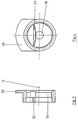
- FIG. 2 shows the view of the end face of the motor 10 provided with the spring device 20, from which it can be seen how the leaf spring 22 rests quasi tangentially on the rotor shaft 14.
- Fig. 3 is a longitudinal section through the spring device 20 described above, which engages around the support bearing 18 for the rotor shaft 14 in the installed state, is shown on an enlarged scale. From this it can be clearly seen that the leaf spring 22 of the spring device 20 has an outer contour curved toward the shaft 14 in order to keep the contact area with the rotor shaft 14 as small as possible and thus to minimize the resulting friction losses.
- FIG. 4 shows an enlarged representation of the view of the outer end face of the spring device 20.
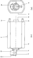
- the electric motor 10 is also an electric motor 11 according to the invention with a housing 12 in a side view shown.
- the electric motor 10 also has a stator and a rotor, as well as a rotor shaft 14, to which the rotor is connected and which is mounted on the left end face 16 of the housing 12 in FIG. 4 in a first bearing 18 and from which a shaft end 15 protrudes.
- the first bearing 18 cooperates with a magnet device 26 which encompasses the bearing 18 in a ring-like manner and on the end face outer surface directly acts on the shaft end of the rotor shaft 14 emerging here with a magnet 28 directed radially on one side.
- a magnet device 26 which encompasses the bearing 18 in a ring-like manner and on the end face outer surface directly acts on the shaft end of the rotor shaft 14 emerging here with a magnet 28 directed radially on one side.
- the rotor shaft 14 is acted upon by the existing fit clearance in the direction facing away from the magnet 28, as a result of which the existing fit clearance is compensated for and possible noise developments caused by the fit clearance are suppressed.
- a bearing plate 19 is provided with a further bearing, in which the associated end of the rotor shaft 14 is mounted.
- connection contacts 24, 25 for the electrical power supply of the motor 10 are arranged on this end face.
- FIG. 6 shows the view of the end face of the motor 11 provided with the magnet device 26, from which it can be seen how the magnet 28 is arranged quasi tangentially at a distance from the rotor shaft 14 and acts on the rotor shaft 14 with its magnetic field.
- FIG. 7 shows a longitudinal section through the above-described magnet device 26, which in the installed state encompasses the support bearing 18 for the rotor shaft 14, on an enlarged scale.
- FIG. 8 shows an enlarged representation of the view of the outer end face of the magnet device 26.
Landscapes
- Engineering & Computer Science (AREA)
- Power Engineering (AREA)
- Motor Or Generator Frames (AREA)
- Iron Core Of Rotating Electric Machines (AREA)
- Connection Of Motors, Electrical Generators, Mechanical Devices, And The Like (AREA)
- Valve Device For Special Equipments (AREA)
- Transition And Organic Metals Composition Catalysts For Addition Polymerization (AREA)
- Glass Compositions (AREA)
Abstract
Description
- Die Erfindung betrifft einen Elektromotor mit einem Gehäuse, das einen Stator aufnimmt, in welchem ein Rotor mit einer Rotorwelle drehbar angeordnet ist, sowie mit stirnseitig angeordneten Lagern für die Rotorwelle.
- Es ist allgemein bekannt, daß Elektromotoren in einem Motorgehäuse einen stationären, gehäusefesten Ständer und einen hierin drehbaren Läufer aufweisen. Der Rotor ist hierbei auf einer Rotorwelle angeordnet, die ihrerseits in an beiden Stirnseiten des Motorgehäuses angeordneten, sogenannten Lagerschilden gelagert ist. Für die Stromversorgung der Statorwicklung und die am Läufer angeordnete Läuferwicklung, in welcher ein Gegenfeld erzeugt wird, sind ferner Anschlußklemmen vorgesehen, welche jeweils mit den zugeordneten Wicklungen verbunden sind.
- Bei der modernen Fertigung von Elektromotoren in Großserien, wie sie heutzutage üblich ist, treten zwangläufig zwischen den einzelnen Bauteilen Toleranzen auf, die auf die fehlerfreie Funktion des Elektromotors keine Auswirkung haben, jedoch eine zum Teil störende Geräuschentwicklung hervorrufen.
- Eine wesentliche Ursache für diese Geräuschentwicklung ist die Lagerung für die Rotorwelle, welche in den vorgesehenen Lagern in den Lagerschilden geführt ist. Dabei sind die Wellen zwar mit der vorgeschriebenen Toleranz in die Lager eingepaßt, doch führen Toleranzen, die Oberflächenbeschaffenheit des Rotors und dessen Abweichung von der Geradheit, das heißt die Abweichung seiner Geometrie von den Vorgaben, zu entsprechenden Unwuchten, die sich wiederum auf die vom Lager aufzunehmenden Belastungen auswirken. So hat sich gezeigt, daß insbesondere bei radialen Lagerbelastungen, wie sie beim Einsatz des Motors als Exzenterantrieb auftreten, zum Beispiel in Rasierapparaten, Haarschneidern und dgl., die von den Lagern ausgehende Geräuschentwicklung deutlich erhöht ist.
- Ausgehend von diesem Stand der Technik ist es Aufgabe der Erfindung, einen Elektromotor der eingangs genannten Art zu schaffen, der aufgrund seiner Gestaltung möglichst geräuscharm betrieben werden kann, wobei er einfach herstellbar sein soll.
- Diese Aufgabe wird erfindungsgemäß durch die kennzeichnenden Merkmale des Patentanspruches 1 gelöst. Weiterentwicklungen und Verbesserungen sind in den abhängigen Patentansprüchen angegeben.
- Entsprechend der Erfindung ist zur Lösung der vorstehend angegebenen Aufgabe vorgesehen, daß die Rotorwelle an einem ihrer beiden Enden gezielt einseitig von einer radial gerichteten Kraft beaufschlagt ist. Hiermit wird das erwähnte Passungsspiel zwischen der Rotorwelle und dem Lager beziehungsweise zwischen der Rotorwelle und dem Gehäuse minimiert, indem die Welle in bezug auf ihre Längsachse um den Betrag des vorhandenen Passungsspiels seitlich ausgelenkt wird und damit einer gewissen
- Vorspannung unterliegt, wodurch eine ohne derartige Maßnahmen aus dem Lagerspiel beziehungsweise dem Passungsspiel resultierende Geräuschentwicklung unterdrückt wird. Grundsätzlich mögliche, hierdurch hervorgerufene Bremseffekte für die Rotorwelle sind vernachlässigbar gering.
- Gemäß einer bevorzugten Ausführungsform der Erfindung ist zur Aufbringung der Radialkraft ein Federelement vorgesehen, welches die radial gerichtete Kraft einseitig auf ein Ende der Rotorwelle ausübt.
- In vorteilhafter Weiterbildung des erfindungsgemäßen Motors kann das Federelement aus Metall oder aus Kunststoff bestehen. Die erforderlichen Auslenkkräfte sind derart gering, daß die Verwendung von Kunststoffedern als unproblematisch anzusehen ist.
- Gemäß einer bevorzugten Ausgestaltung der Erfindung ist als Federelement eine Blattfeder vorgesehen, die am Gehäuse eingespannt ist und sich mit der erforderlichen Vorspannung gegen das vorgesehene Wellenende anlegt.
- Gemäß einer vorteilhaften Weiterbildung der Erfindung kann vorgesehen sein, daß das Federelement das Ende der Rotorwelle mittelbar, nämlich unter Zwischenfügung eines Druckstücks beaufschlagt.
- Ein derartiges Druckstück, das insbesondere dazu dient, die radiale wie auch gegebenenfalls die axiale Führung der Rotorwelle zu gewährleisten, indem es der Wellenkontur angepaßt ist, kann vorteilhafterweise aus abriebfestem Kunststoff bestehen, insbesondere aus PTFE oder aus Polyamid, aber auch aus einem Metallkörper, zum Beispiel mit einer Auflage aus Lagermetall.
- Zusätzlich kann vorgesehen sein, daß das Druckstück eine Filzauflage aufweist, welche mit der Rotorwelle unmittelbar zusammenarbeitet. Diese Filzauflage ist vorteilhafterweise mit einem gleitgünstigen Schmiermittel getränkt, um den Reibungswiderstand zu minimieren.
- Eine weitere Ausgestaltung sieht vor, daß das zur Geräuschminderung vorgesehene Federelement das dem betreffenden Wellenende zugeordnete Lager beaufschlagt. Diese Lösung hat den Vorteil, daß die erwähnten Reibungskräfte so gering wie möglich gehalten werden und der Reibverschleiß an der Welle beziehungsweise an dem Federelement vermieden wird.
- Entsprechend einer alternativen, quasi reibungsfreien Ausführungsform der erfindungsgemäßen Einrichtung zur Geräuschminderung des Elektromotors ist vorgesehen, daß die Rotorwelle an dem betreffenden Ende eine Permeabilität µ R > 1 aufweist, vorzugsweise eine Permeabilität µ R >> 1, und daß dieses Wellenende gezielt einseitig radial mit Magnetkraft beaufschlagt ist.
- Hierbei macht sich die Erfindung zunutze, daß die Rotorwellen von Elektromotoren ebenso wie die Rotoren selbst üblicherweise aus ferromagnetischen Werkstoffen gefertigt sind.
- Es kann aber auch vorgesehen sein, wenn der Wellenwerkstoff eine Permeabilität µ R < 1 aufweist, daß das mit Magnetkraft beaufschlagte Wellenende der Rotorwelle mit einem Zusatzteil versehen ist, welches eine Permeabilität µ R > 1 aufweist und die Belastung aus der aufgenommenen Magnetkraft auf das Wellenende überträgt.
- Vorteilhafterweise kann dem betreffenden Wellenende ein Magnet mit einem einseitig radial auf das Wellenende gerichteten Magnetfeld zugeordnet sein, welcher die zur Unterdrückung des geräuschbegünstigenden Passungsspiels erforderliche Magnetkraft liefert. Dabei kann der Magnet als Permanentmagnet oder als Elektromagnet ausgebildet sein.
- Zwar ist die erfindungsgemäße Einrichtung zur Geräuschminderung grundsätzlich für alle Elektromotoren geeignet, doch ist die Anwendung der Erfindung insbesondere vorgesehen für Klein- und Kleinstmotoren, wie sie üblicherweise als Antriebsmotoren für die erwähnten elektrischen Rasierapparate, Haarschneidegeräte und ähnliche schnellaufende elektrische Geräte eingesetzt werden, bei denen ein hoher Geräuschpegel als störend empfunden wird.
- Anhand eines in der Zeichnung dargestellten Ausführungsbeispieles sollen die Erfindung, vorteilhafte Ausgestaltungen und Verbesserungen der Erfindung näher erläutert und beschrieben werden.
- Es zeigen:
- Fig. 1
- eine Seitenansicht eines erfindungsgemäßen Elektromotors mit einer ersten Einrichtung zur Geräuschminderung;
- Fig. 2
- eine Stirnansicht auf den Motor gemäß Fig. 1 mit der ersten Einrichtung zur Geräuschminderung;
- Fig. 3
- eine Einzelheit "I" der in Fig. 1 dargestellten ersten Einrichtung zur Geräuschminderung von der Seite;
- Fig. 4
- eine Stirnansicht der Einzelheit gemäß Fig. 3;
- Fig. 5
- eine Seitenansicht eines erfindungsgemäßen Elektromotors mit einer alternativen Einrichtung zur Geräuschminderung;
- Fig. 6
- eine Stirnansicht auf den Motor gemäß Fig. 1 zweiten Einrichtung zur Geräuschminderung;
- Fig. 7
- eine Einzelheit "V" der Darstellung in Fig. 1 von der Seite mit der zweiten Einrichtung zur Geräuschminderung und
- Fig. 8
- eine Stirnansicht der Einzelheit gemäß Fig. 3;
- In Fig. 1 ist ein erfindungsgemäßer Elektromotor 10 mit einem Gehäuse 12 in Seitenansicht dargestellt. Der Elektromotor 10 besitzt wie alle solche Motoren einen Stator und einen Rotor, die in dieser Ansicht von der Außenwand des Gehäuses 12 verdeckt sind, sowie eine Rotorwelle 14, mit welcher der Rotor verbunden ist und die an der in Fig. 1 linken Stirnseite 16 des Gehäuses 12 in einem ersten Lager 18 gelagert ist und aus welcher ein Wellenende 15 herausragt.
- Das erste Lager 18 arbeitet mit einer Federeinrichtung 20 zusammen, welche das Lager 18 ringartig umgreift und an der stirnseitigen Außenfläche unmittelbar das hier austretende Weilenende der Rotorwelle 14 mit einer Blattfeder 22 einseitig radial beaufschlagt. Hierdurch wird die Rotorwelle um das bestehende Passungsspiel in die der Feder abgewandte Richtung gedrückt, wodurch das bestehende Passungsspiel kompensiert wird und mögliche, durch das Passungsspiel hervorgerufene Geräuschentwicklungen unterdrückt werden.
- An der gegenüberliegenden Stirnseite 17 des Gehäuses 12 ist ein Lagerschild 19 mit einem weiteren Lager vorgesehen, in welchem das zugeordnete Ende der Rotorwelle 14 gelagert ist. Außerdem sind an dieser Stirnseite Anschlußkontakte 24, 25 für die elektrische Stromversorgung des Motors 10 angeordnet.
- In den weiteren Fig. sind gleiche Teile mit den gleichen Bezugsziffern bezeichnet, so daß sich diesbezügliche Erläuterungen erübrigen und die Beschreibung nur auf die jeweiligen Besonderheiten der Darstellungen eingeht.
- In Fig. 2 ist die Ansicht der mit der Federeinrichtung 20 versehenen Stirnseite des Motors 10 wiedergegeben, woraus ersichtlich ist, wie die Blattfeder 22 quasi tangential an der Rotorwelle 14 anliegt.
- In Fig. 3 ist ein Längsschnitt durch die zuvor beschriebene Federeinrichtung 20, welche in eingebautem Zustand das Stützlager 18 für die Rotorwelle 14 umgreift, in vergrößertem Maßstab dargestellt. Hieraus ist deutlich zu erkennen, daß die Blattfeder 22 der Federeinrichtung 20 eine zur Welle 14 hin gekrümmte Außenkontur aufweist, um die Kontaktfläche mit der Rotorwelle 14 möglichst klein zu halten und so die hieraus resultierenden Reibungsverluste zu minimieren.
- In Fig. 4 schließlich ist eine vergrößerte Wiedergabe der Ansicht der außenliegenden Stirnseite der Federeinrichtung 20 gezeigt.
- In Fig. 5 ist ebenfalls ein erfindungsgemäßer Elektromotor 11 mit einem Gehäuse 12 in Seitenansicht dargestellt. Der Elektromotor 10 besitzt ebenfalls einen Stator und einen Rotor sowie eine Rotorwelle 14, mit welcher der Rotor verbunden ist und die an der in Fig. 4 linken Stirnseite 16 des Gehäuses 12 in einem ersten Lager 18 gelagert ist und aus welcher ein Wellenende 15 herausragt.
- Das erste Lager 18 arbeitet mit einer Magneteinrichtung 26 zusammen, welche das Lager 18 ringartig umgreift und an der stirnseitigen Außenfläche unmittelbar das hier austretende Wellenende der Rotorwelle 14 mit einem Magneten 28 einseitig radial gerichtet beaufschlagt. Auch hier wird die Rotorwelle 14 um das bestehende Passungsspiel in die dem Magneten 28 abgewandte Richtung beaufschlagt, wodurch das bestehende Passungsspiel kompensiert wird und mögliche, durch das Passungsspiel hervorgerufene Geräuschentwicklungen unterdrückt werden.
- An der gegenüberliegenden Stirnseite 17 des Gehäuses 12 ist in gleicher Weise wie zuvor bei dem Motor gemäß Fig. 1 bis 4 ein Lagerschild 19 mit einem weiteren Lager vorgesehen, in welchem das zugeordnete Ende der Rotorwelle 14 gelagert ist. Außerdem sind an dieser Stirnseite Anschlußkontakte 24, 25 für die elektrische Stromversorgung des Motors 10 angeordnet.
- In Fig. 6 ist die Ansicht der mit der Magneteinrichtung 26 versehenen Stirnseite des Motors 11 wiedergegeben, woraus ersichtlich ist, wie der Magnet 28 quasi tangential im Abstand zu der Rotorwelle 14 angeordnet ist und diese mit seinem Magnetfeld beaufschlagt.
- In Fig. 7 ist ein Längsschnitt durch die zuvor beschriebene Magneteinrichtung 26, welche in eingebautem Zustand das Stützlager 18 für die Rotorwelle 14 umgreift, in vergrößertem Maßstab dargestellt. Hieraus ist deutlich zu erkennen, daß der Magnet 28 der Magneteinrichtung 26 einen Abstand zur Welle 14 hin aufweist und auf diese Weise jeglichen Reibkontakt mit der Rotorwelle 14 vermeidet.
- In Fig. 8 schließlich ist eine vergrößerte Wiedergabe der Ansicht der außenliegenden Stirnseite der Magneteinrichtung 26 gezeigt.
-
- 10
- Elektromotor
- 11
- Elektromotor
- 12
- Gehäuse
- 14
- Rotorwelle
- 16
- Wellenstumpf/ Wellenende
- 18
- Lager
- 19
- Lagerschild
- 20
- Federeinrichtung
- 22
- Blattfeder
- 24
- Anschlußkontakte
- 25
- Anschlußkontakte
- 26
- Magneteinrichtung
- 28
- Magnet
Claims (15)
- Elektromotor (11) mit einem Gehäuse (12) mit einem darin angeordneten Stator und mit einem im Stator drehbar angeordneten Rotor mit einer Rotorwelle (14), die den Stator zentral durchgreift und in an dessen Stirnseiten angeordneten Lagern (18, 19) mit ihren Enden (15) gelagert ist,
dadurch gekennzeichnet, daß
die Rotorwelle (14) an einem ihrer Enden (15) gezielt einseitig von einer radial gerichteten Kraft beaufschlagt ist. - Motor nach Anspruch 1, dadurch gekennzeichnet, daß eine Federeinrichtung (20) mit einem Federelement (22) vorgesehen ist, welches die radial gerichtete Kraft einseitig auf ein Wellenende (15) der Rotorwelle (14) ausübt.
- Motor nach Anspruch 1 oder 2, dadurch gekennzeichnet, daß das Federelement (22) aus Metall besteht.
- Motor nach Anspruch 1 oder 2, dadurch gekennzeichnet, daß das Federelement (22) aus Kunststoff besteht.
- Motor nach einem der Ansprüche 2 bis 4, dadurch gekennzeichnet, daß als Federelement (22) eine Blattfeder vorgesehen ist.
- Motor nach Anspruch 3 oder 4, dadurch gekennzeichnet, daß das Federelement (22) das dem betreffenden Wellenende (15) zugeordnete Lager (18) beaufschlagt.
- Motor nach einem der Ansprüche 2 bis 5, dadurch gekennzeichnet, daß das Federelement (22) das Ende (15) der Rotorwelle (14) mittelbar unter Zwischenfügung eines Druckstücks beaufschlagt.
- Motor nach Anspruch 7, dadurch gekennzeichnet, daß das Druckstück aus abriebfestem Kunststoff besteht, insbesondere aus PTFE oder aus Polyamid.
- Motor nach Anspruch 7 oder 8, dadurch gekennzeichnet, daß das Druckstück eine Filzauflage aufweist, welche mit der Rotorwelle (14) unmittelbar zusammenarbeitet.
- Motor nach Anspruch 7, dadurch gekennzeichnet, daß das Druckstück als zusätzliches Lager, insbesondere als Sinterlager, ausgebildet ist.
- Motor nach Anspruch 1, dadurch gekennzeichnet, daß die Rotorwelle (14) an dem betreffenden Ende (15) eine Permeabilität µ R > 1 aufweist und daß dieses Wellenende (15) gezielt einseitig radial mit Magnetkraft beaufschlagt ist.
- Motor nach Anspruch 11, dadurch gekennzeichnet, daß das mit Magnetkraft beaufschlagte Wellenende (15) mit einem Zusatzteil mit einer Permeabilität µ R > 1 versehen ist, welches die Belastung aus der Magnetkraft auf das Wellenende (15) überträgt.
- Motor nach Anspruch 11 oder 12, dadurch gekennzeichnet, daß eine Magneteinrichtung (26) an dem betreffenden Wellenende (15) angeordnet ist und daß ein Magnet (28) an dem betreffenden Wellenende (15) mit einem einseitig radial auf das Wellenende gerichteten Magnetfeld zugeordnet ist.
- Motor nach Anspruch 13, dadurch gekennzeichnet, daß dem Wellenende (15) ein Permanentmagnet (28) zugeordnet ist.
- Motor nach Anspruch 13, dadurch gekennzeichnet, daß dem Wellenende ein Elektromagnet zugeordnet ist.
Applications Claiming Priority (2)
| Application Number | Priority Date | Filing Date | Title |
|---|---|---|---|
| DE19617448A DE19617448A1 (de) | 1996-05-02 | 1996-05-02 | Elektromotor |
| DE19617448 | 1996-05-02 |
Publications (3)
| Publication Number | Publication Date |
|---|---|
| EP0805543A2 true EP0805543A2 (de) | 1997-11-05 |
| EP0805543A3 EP0805543A3 (de) | 2000-08-30 |
| EP0805543B1 EP0805543B1 (de) | 2009-07-01 |
Family
ID=7792996
Family Applications (1)
| Application Number | Title | Priority Date | Filing Date |
|---|---|---|---|
| EP97107063A Expired - Lifetime EP0805543B1 (de) | 1996-05-02 | 1997-04-29 | Elektromotor |
Country Status (5)
| Country | Link |
|---|---|
| EP (1) | EP0805543B1 (de) |
| JP (1) | JPH1051992A (de) |
| AT (1) | ATE435514T1 (de) |
| DE (2) | DE19617448A1 (de) |
| ES (1) | ES2328090T3 (de) |
Cited By (1)
| Publication number | Priority date | Publication date | Assignee | Title |
|---|---|---|---|---|
| EP1601088A3 (de) * | 2004-05-24 | 2007-04-18 | Minebea Co. Ltd. | Schrittmotor zur Verwendung in Umgebungen mit hoher Temperatur |
Families Citing this family (5)
| Publication number | Priority date | Publication date | Assignee | Title |
|---|---|---|---|---|
| DE19854535A1 (de) * | 1998-11-26 | 2000-06-15 | Valeo Auto Electric Gmbh | Antriebsvorrichtung, insbesondere für eine Scheibenwischanlage eines Kraftfahrzeugs |
| US6739053B2 (en) | 2000-12-14 | 2004-05-25 | Wahl Clipper Corporation | Hair clipping device with internal vacuum |
| US6684511B2 (en) | 2000-12-14 | 2004-02-03 | Wahl Clipper Corporation | Hair clipping device with rotating bladeset having multiple cutting edges |
| DE10145558B4 (de) * | 2001-09-14 | 2006-05-18 | Bühler Motor GmbH | Stellantrieb, insbesondere für einen Schwenkantrieb in oder an Kraftfahrzeugen |
| US8844142B2 (en) | 2011-03-18 | 2014-09-30 | Spectrum Brands, Inc. | Adjustable comb assembly for hair cutting appliance |
Family Cites Families (13)
| Publication number | Priority date | Publication date | Assignee | Title |
|---|---|---|---|---|
| DE7116069U (de) * | 1971-04-26 | 1972-01-05 | Gebhardt W Kg | Achsenlagerung von Antriebsaggregaten |
| US4079274A (en) * | 1976-11-17 | 1978-03-14 | General Time Corporation | Damping of noise |
| DE2711560A1 (de) * | 1977-03-17 | 1978-09-21 | Weiss Paul Fa | Wellenlager fuer gleichstrom-kleinmotore |
| CH621456B (de) * | 1977-08-31 | Sodeco Compteurs De Geneve | Kleinsynchronmotor. | |
| DE3336385A1 (de) * | 1983-10-06 | 1985-04-25 | Philips Patentverwaltung Gmbh, 2000 Hamburg | Antriebsvorrichtung mit einem einphasensynchronmotor |
| DE3543544A1 (de) * | 1985-12-10 | 1987-06-11 | Bosch Gmbh Robert | Vorrichtung zur lueftergeraeuschminderung und -daempfung bei drehstromgeneratoren |
| JPS6318949A (ja) * | 1986-07-09 | 1988-01-26 | Matsushita Electric Ind Co Ltd | 小型モ−タの振動防止装置 |
| NL8800914A (nl) * | 1988-04-08 | 1989-11-01 | Unihef Automobiel Bv | Voertuig met op en neer beweegbare laadvloer. |
| JPH01283041A (ja) * | 1988-05-06 | 1989-11-14 | Mitsubishi Electric Corp | モータ軸の振動抑制装置 |
| US5355042A (en) * | 1988-09-09 | 1994-10-11 | University Of Virginia Patent Foundation | Magnetic bearings for pumps, compressors and other rotating machinery |
| DE3840587C1 (en) * | 1988-12-02 | 1989-12-28 | Elektromotoren Werke Karl Kaiser Gmbh & Co, 2350 Neumuenster, De | Drawing-roller drive |
| DE69306422T2 (de) * | 1992-01-24 | 1997-06-05 | Philips Electronics Nv | Getriebe mit veränderlicher mechanischer Vorspannung |
| JPH08140306A (ja) * | 1994-11-11 | 1996-05-31 | Tokyo Parts Ind Co Ltd | ギヤードアクチュエーター |
-
1996
- 1996-05-02 DE DE19617448A patent/DE19617448A1/de not_active Withdrawn
-
1997
- 1997-04-29 ES ES97107063T patent/ES2328090T3/es not_active Expired - Lifetime
- 1997-04-29 EP EP97107063A patent/EP0805543B1/de not_active Expired - Lifetime
- 1997-04-29 AT AT97107063T patent/ATE435514T1/de not_active IP Right Cessation
- 1997-04-29 DE DE59713012T patent/DE59713012D1/de not_active Expired - Lifetime
- 1997-05-02 JP JP9114750A patent/JPH1051992A/ja active Pending
Cited By (1)
| Publication number | Priority date | Publication date | Assignee | Title |
|---|---|---|---|---|
| EP1601088A3 (de) * | 2004-05-24 | 2007-04-18 | Minebea Co. Ltd. | Schrittmotor zur Verwendung in Umgebungen mit hoher Temperatur |
Also Published As
| Publication number | Publication date |
|---|---|
| JPH1051992A (ja) | 1998-02-20 |
| EP0805543B1 (de) | 2009-07-01 |
| DE19617448A1 (de) | 1997-11-13 |
| EP0805543A3 (de) | 2000-08-30 |
| DE59713012D1 (de) | 2009-08-13 |
| ES2328090T3 (es) | 2009-11-06 |
| ATE435514T1 (de) | 2009-07-15 |
Similar Documents
| Publication | Publication Date | Title |
|---|---|---|
| DE60023782T2 (de) | Kleinstmotor und sein Herstellungsverfahren | |
| DE102004030830B4 (de) | Bremsenaufbau für eine Traktionsmaschine | |
| EP0563583A1 (de) | Motorantrieb,insbesondere elektromotorischer Fenster- oder Schiebedachantrieb | |
| EP1584130A1 (de) | Vorgespannte lagerung für elektrische maschinen | |
| DE29513700U1 (de) | Motor-Getriebe-Antriebseinheit, insbesondere für einen Kraftfahrzeug-Fensterheberantrieb o.dgl. | |
| EP1609228A1 (de) | Elektrische maschine mit in den stator integrierter rotorlagerung | |
| EP1348077B1 (de) | Kältemittelverdichter | |
| EP1090201A1 (de) | Elektromotorischer antrieb, insbesondere fensterheberantrieb für ein kraftfahrzeug | |
| EP1145410A1 (de) | Scheibenläufermotor mit lagervorspannung | |
| EP0805543B1 (de) | Elektromotor | |
| DE10160847A1 (de) | Betätigungsvorrichtung, insbesondere zur Betätigung von Sperrdifferentialen von Fahrzeugen | |
| DE102011121935B4 (de) | Lagerbuchse mit Lager zur Verwendung in einer elektrischen Maschine | |
| WO2021005151A1 (de) | Druckversorgungseinrichtung mit einer zahnradpumpe | |
| DE102021109493A1 (de) | AUßENLÄUFERMOTOR MIT KRAFTÜBERTRAGUNGSABSCHNITT | |
| DE29624386U1 (de) | Elektromotor | |
| DE3721757C2 (de) | ||
| DE4206761C2 (de) | Lageranordnung für Rotoren elektrischer Maschinen | |
| WO2009049807A1 (de) | Elektromotor zur verwendung in einem zahnärztlichen, zahnmedizinischen oder dentaltechnischen handstück | |
| EP2600503B1 (de) | Bürstendeckel für einen bürstenkommutierten Elektromotor und Elektromotor | |
| DE102009046603A1 (de) | Elektrische Maschine mit reduzierter Geräuschentwicklung | |
| DE102007023389A1 (de) | Wellenanlaufanordnung; Stellantrieb sowie Fensterhebereinrichtung | |
| WO2004040735A1 (de) | Antriebsvorrichtung | |
| EP0259714A1 (de) | Anlaufscheibe | |
| DE10042405A1 (de) | Lageraufnahme | |
| DE19718723C2 (de) | Drehsensor-Anordnung |
Legal Events
| Date | Code | Title | Description |
|---|---|---|---|
| PUAI | Public reference made under article 153(3) epc to a published international application that has entered the european phase |
Free format text: ORIGINAL CODE: 0009012 |
|
| AK | Designated contracting states |
Kind code of ref document: A2 Designated state(s): AT CH DE ES FR GB IT LI NL |
|
| PUAL | Search report despatched |
Free format text: ORIGINAL CODE: 0009013 |
|
| AK | Designated contracting states |
Kind code of ref document: A3 Designated state(s): AT CH DE ES FR GB IT LI NL |
|
| 17P | Request for examination filed |
Effective date: 20001026 |
|
| RAP1 | Party data changed (applicant data changed or rights of an application transferred) |
Owner name: WAHL GMBH |
|
| 17Q | First examination report despatched |
Effective date: 20041011 |
|
| GRAP | Despatch of communication of intention to grant a patent |
Free format text: ORIGINAL CODE: EPIDOSNIGR1 |
|
| GRAS | Grant fee paid |
Free format text: ORIGINAL CODE: EPIDOSNIGR3 |
|
| GRAA | (expected) grant |
Free format text: ORIGINAL CODE: 0009210 |
|
| AK | Designated contracting states |
Kind code of ref document: B1 Designated state(s): AT CH DE ES FR GB IT LI NL |
|
| REG | Reference to a national code |
Ref country code: GB Ref legal event code: FG4D Free format text: NOT ENGLISH |
|
| REG | Reference to a national code |
Ref country code: CH Ref legal event code: EP |
|
| REF | Corresponds to: |
Ref document number: 59713012 Country of ref document: DE Date of ref document: 20090813 Kind code of ref document: P |
|
| REG | Reference to a national code |
Ref country code: ES Ref legal event code: FG2A Ref document number: 2328090 Country of ref document: ES Kind code of ref document: T3 |
|
| PLBE | No opposition filed within time limit |
Free format text: ORIGINAL CODE: 0009261 |
|
| STAA | Information on the status of an ep patent application or granted ep patent |
Free format text: STATUS: NO OPPOSITION FILED WITHIN TIME LIMIT |
|
| 26N | No opposition filed |
Effective date: 20100406 |
|
| REG | Reference to a national code |
Ref country code: CH Ref legal event code: PL |
|
| PG25 | Lapsed in a contracting state [announced via postgrant information from national office to epo] |
Ref country code: LI Free format text: LAPSE BECAUSE OF NON-PAYMENT OF DUE FEES Effective date: 20100430 Ref country code: CH Free format text: LAPSE BECAUSE OF NON-PAYMENT OF DUE FEES Effective date: 20100430 |
|
| PG25 | Lapsed in a contracting state [announced via postgrant information from national office to epo] |
Ref country code: AT Free format text: LAPSE BECAUSE OF NON-PAYMENT OF DUE FEES Effective date: 20100429 |
|
| REG | Reference to a national code |
Ref country code: FR Ref legal event code: PLFP Year of fee payment: 19 |
|
| PGFP | Annual fee paid to national office [announced via postgrant information from national office to epo] |
Ref country code: NL Payment date: 20150422 Year of fee payment: 19 |
|
| PGFP | Annual fee paid to national office [announced via postgrant information from national office to epo] |
Ref country code: GB Payment date: 20150423 Year of fee payment: 19 Ref country code: DE Payment date: 20150521 Year of fee payment: 19 Ref country code: ES Payment date: 20150427 Year of fee payment: 19 |
|
| PGFP | Annual fee paid to national office [announced via postgrant information from national office to epo] |
Ref country code: FR Payment date: 20150422 Year of fee payment: 19 Ref country code: IT Payment date: 20150427 Year of fee payment: 19 |
|
| REG | Reference to a national code |
Ref country code: DE Ref legal event code: R119 Ref document number: 59713012 Country of ref document: DE |
|
| REG | Reference to a national code |
Ref country code: NL Ref legal event code: MM Effective date: 20160501 |
|
| GBPC | Gb: european patent ceased through non-payment of renewal fee |
Effective date: 20160429 |
|
| REG | Reference to a national code |
Ref country code: FR Ref legal event code: ST Effective date: 20161230 |
|
| PG25 | Lapsed in a contracting state [announced via postgrant information from national office to epo] |
Ref country code: GB Free format text: LAPSE BECAUSE OF NON-PAYMENT OF DUE FEES Effective date: 20160429 Ref country code: DE Free format text: LAPSE BECAUSE OF NON-PAYMENT OF DUE FEES Effective date: 20161101 Ref country code: FR Free format text: LAPSE BECAUSE OF NON-PAYMENT OF DUE FEES Effective date: 20160502 Ref country code: NL Free format text: LAPSE BECAUSE OF NON-PAYMENT OF DUE FEES Effective date: 20160501 |
|
| PG25 | Lapsed in a contracting state [announced via postgrant information from national office to epo] |
Ref country code: IT Free format text: LAPSE BECAUSE OF NON-PAYMENT OF DUE FEES Effective date: 20160429 |
|
| REG | Reference to a national code |
Ref country code: ES Ref legal event code: FD2A Effective date: 20180507 |
|
| PG25 | Lapsed in a contracting state [announced via postgrant information from national office to epo] |
Ref country code: ES Free format text: LAPSE BECAUSE OF NON-PAYMENT OF DUE FEES Effective date: 20160430 |