EP0805514B1 - Selbst-Eichung einer Gruppenantenne mit ungleichmässiger gegenseitiger Kupplung der Antennenelemente und willkürlicher Orientierung des Antennnengitters - Google Patents
Selbst-Eichung einer Gruppenantenne mit ungleichmässiger gegenseitiger Kupplung der Antennenelemente und willkürlicher Orientierung des Antennnengitters Download PDFInfo
- Publication number
- EP0805514B1 EP0805514B1 EP97107195A EP97107195A EP0805514B1 EP 0805514 B1 EP0805514 B1 EP 0805514B1 EP 97107195 A EP97107195 A EP 97107195A EP 97107195 A EP97107195 A EP 97107195A EP 0805514 B1 EP0805514 B1 EP 0805514B1
- Authority
- EP
- European Patent Office
- Prior art keywords
- elements
- phase
- lattice
- array
- interleaved
- Prior art date
- Legal status (The legal status is an assumption and is not a legal conclusion. Google has not performed a legal analysis and makes no representation as to the accuracy of the status listed.)
- Expired - Lifetime
Links
- 230000008878 coupling Effects 0.000 title claims description 45
- 238000010168 coupling process Methods 0.000 title claims description 45
- 238000005859 coupling reaction Methods 0.000 title claims description 45
- 238000000034 method Methods 0.000 claims description 57
- 238000005259 measurement Methods 0.000 claims description 29
- QNRATNLHPGXHMA-XZHTYLCXSA-N (r)-(6-ethoxyquinolin-4-yl)-[(2s,4s,5r)-5-ethyl-1-azabicyclo[2.2.2]octan-2-yl]methanol;hydrochloride Chemical compound Cl.C([C@H]([C@H](C1)CC)C2)CN1[C@@H]2[C@H](O)C1=CC=NC2=CC=C(OCC)C=C21 QNRATNLHPGXHMA-XZHTYLCXSA-N 0.000 claims description 11
- 230000005540 biological transmission Effects 0.000 claims description 9
- 238000012937 correction Methods 0.000 claims description 7
- 229920000126 latex Polymers 0.000 claims 1
- 238000012360 testing method Methods 0.000 description 7
- 230000005284 excitation Effects 0.000 description 5
- 238000012546 transfer Methods 0.000 description 5
- 239000000523 sample Substances 0.000 description 3
- 238000003491 array Methods 0.000 description 2
- 230000001419 dependent effect Effects 0.000 description 2
- 230000003213 activating effect Effects 0.000 description 1
- 238000010586 diagram Methods 0.000 description 1
- 230000000694 effects Effects 0.000 description 1
- 239000011159 matrix material Substances 0.000 description 1
- 238000012544 monitoring process Methods 0.000 description 1
- 238000012545 processing Methods 0.000 description 1
- 238000001228 spectrum Methods 0.000 description 1
Images

Classifications
-
- H—ELECTRICITY
- H01—ELECTRIC ELEMENTS
- H01Q—ANTENNAS, i.e. RADIO AERIALS
- H01Q3/00—Arrangements for changing or varying the orientation or the shape of the directional pattern of the waves radiated from an antenna or antenna system
- H01Q3/26—Arrangements for changing or varying the orientation or the shape of the directional pattern of the waves radiated from an antenna or antenna system varying the relative phase or relative amplitude of energisation between two or more active radiating elements; varying the distribution of energy across a radiating aperture
- H01Q3/267—Phased-array testing or checking devices
-
- H—ELECTRICITY
- H01—ELECTRIC ELEMENTS
- H01Q—ANTENNAS, i.e. RADIO AERIALS
- H01Q3/00—Arrangements for changing or varying the orientation or the shape of the directional pattern of the waves radiated from an antenna or antenna system
- H01Q3/26—Arrangements for changing or varying the orientation or the shape of the directional pattern of the waves radiated from an antenna or antenna system varying the relative phase or relative amplitude of energisation between two or more active radiating elements; varying the distribution of energy across a radiating aperture
- H01Q3/2605—Array of radiating elements provided with a feedback control over the element weights, e.g. adaptive arrays
- H01Q3/2652—Self-phasing arrays
Definitions
- This invention relates to phased array antennas, and more particularly to an improved technique for calibrating the array elements to a known amplitude and phase.
- phase-up techniques typically require the use of external measurement facilities such as a nearfield range to provide a reference signal to each element in receive and to measure the output of each element in transmit. As all the elements must be operated at full power to provide the full transmit plane wave spectrum to sample, a great deal of energy is radiated during this testing. This dictates some implementation of high RF power containment, and carries with it a number of safety concerns. It would therefore be advantageous to provide a phase-up technique which minimizes the RF energy output.
- GB 2 171 849 A discloses a method of lining phased array antenna systems e.g. for radar purposes.
- Such an antenna system comprises a number of antenna elements each fed through a signal channel.
- Each such channel includes a module comprising a variable gain control and a variable phase control.
- one channel is selected as a reference channel.
- This one channel is energized and gain and phase control actuating means are appropriately commanded to produce a given gain and phase state in that channel.
- This reference channel is maintained energized at the chosen gain phase throughout the phase alignment procedure.
- a second channel is then selected and energized. The gain in the second channel is adjusted, using data already acquired to be equal to that in the reference channel.
- An instrument of conventional kind is connected between the outputs of the reference channel and the said second channel, to read the difference between the voltages appearing at those outputs.
- the command to phase control activating means of the second channel can be varied, hence varying the phase of the output voltage from the second channel. Then, the second channel is deenergized and isolated, and a third channel energized, when the procedure phase alignment is repeated; and so on through all of the channels to channel N.
- US 5,063,529 A discloses a calibration method for a phased array antenna using automated signal processing techniques to compute calibration coefficients.
- the calibration method disclosed therein uses calibration signals input to the array to generate in-phase and quadrature aperture responses, which are measured and used for computing the calibration coefficients.
- US 5,477,229 discloses a method of calibrating an active antenna, the active element of a transfer function matrix are measured using a near field probe for each radiating source of antenna. The probe is placed in front of each source in succession and each source is excited in turn with the opposite phase and with all the other sources of the array excited normally.
- GB 2,259,778 A discloses a testing radar antenna system.
- each array element is provided with a coupler.
- a test-transmission signal is sampled via the coupler of each active element by a transmission calibration detector, the signal passing via a splitter and a switch.
- a test pulse from a calibration test pulse generator is coupled to each active element and is detected by receiver circuitry.
- the antenna system disclosed therein consists of an antenna having a set of circularly-arrayed radiating columns.
- US 4,176,354 discloses a system an method for monitoring the operability of a radar system having a phased-array antenna system.
- This phased-array system comprises a plurality of identical radiating elements being located to the left and right, respectively, of the array center. It is apparent from the disclosure, the radiating elements are arranged as to lie on a line. Consequently, the phased array system is of an one dimensional type.
- This invention allows for the phase-up of array antennas without the use of a nearfield or farfield range.
- only one element is used in a transmit state at a time, thus reducing the RF energy output.
- Mutual coupling and/or reflections are utilized to provide a signal from one element to its neighbors. This signal provides a reference to allow for elements to be phased with respect to each other.
- the array is phased-up into, at most, four interleaved lattices.
- the invention also provides for a way of phasing the interleaved lattices with respect to each other, thus completing the phase-up process.
- This technique works with any general, regularly spaced, lattice orientation. The technique is applicable to both transmit and receive calibrations.
- a method for achieving phase-up of the radiative elements comprising an array antenna, wherein the elements are arranged in a plurality of spaced, interleaved lattices, comprising the steps of:
- a method for achieving phase-up of the radiative elements comprising an array antenna, wherein the elements are arranged in a rhombic lattice comprises the steps of:
- FIGS. 1A-1D illustrate, respectively, four quadrilateral configurations representing array element lattice positions.
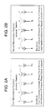
- FIG. 2A illustrates the technique of phasing up the even and odd interleaved lattices of a linear array of elements in receive and transmit, respectively
- FIG. 2B illustrates the technique of phasing up the even and odd lattices in transmit and receive, respectively.
- FIG. 3 illustrates four exemplary elements of a line array.
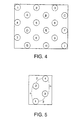
- FIG. 4 is a simplified schematic diagram illustrating a rhombic lattice configuration of an array.
- FIG. 5 illustrates the coupling paths of four elements of the rhombic array of FIG. 4.
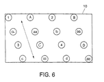
- FIG. 6 is a graphical depiction of the element positions in a parallelogram array lattice.
- This invention involves a method for calibrating the array antenna elements to a known amplitude and phase.
- the elements are generally disposed in accordance with a linear (one dimensional) or a two dimensional polygon configuration.
- a rhombus is a quadrilateral with equal length sides and opposite sides parallel, as indicated in FIG. 1A.
- a square is a special case of a rhombus wherein the angle between any adjacent sides is 90 degrees (FIG. 1B).
- a parallelogram is a quadrilateral with opposite sides parallel (FIG. 1C).
- a rectangle is a special case of a parallelogram where the angle between adjacent sides is 90 degrees (FIG. 1D)
- the corners of these quadrilaterals represent array element lattice positions in exemplary array configurations.
- the case of the linear array will be first discussed, with subsequent discussion of the rhombic and parallelogram cases.
- FIG. 2A shows a line array comprising elements 1-5.
- the sequence begins by transmitting from element 1 as shown in FIG. 2A as transmission T 1 , and simultaneously receiving a measurement signal R in element 2.
- a signal T 2 is then transmitted from element 3, and a measurement signal is received in element 2.
- the phase and gain response from element 2 in this case (reception of the transmitted signal from element 3) is compared to that for the previous measurement (reception of the transmitted signal from element 1). This allows the transmit phase/gain differences between elements 1 and 3 to be computed.
- a receive measurement is then made through element 4.
- the differences in receive phase/gain response for elements 2 and 4 can then be calculated.
- a signal T 3 is transmitted from element 5 and a receive signal is measured in element 4. Data from this measurement allows element 5 transmit phase/gain coefficients to be calculated with respect to transmit excitations for elements 1 and 3.
- the measurement sequences of transmitting from every element and making receive measurements from adjacent elements continues to the end of the array.
- the calibration technique can be applied to arbitrarily sized arrays. Receive measurements using elements other than those adjacent to the transmitting elements may also be used. These additional receive measurements can lead to reduced overall measurement time and increased measurement accuracy.
- Odd Element Receive Phase-up The second series of measurements is aimed at phasing up the odd numbered elements in receive and even numbered elements in transmit. These measurement sequences are similar to those described above for the even element phase-up, and are illustrated in FIG. 2B.
- a transmit signal from element 2 provides excitation for receive measurements from element 1 and then element 3. This allows the relative receive phase/gain responses of elements 1 and 3 to be calculated.
- a transmit signal from element 4 is then used to make receive measurements from element 3 and then element 5. This allows the relative receive phase/gain response of elements 3 and 5 to be calculated. Also, the relative transmit response of element 4 with respect to element 2 can be calculated. All of the coefficients can then be used to provide a receive phase-up of the even elements and a transmit phase-up of the odd elements.
- the interleaved phased-up odd-even elements need to be brought into overall phase/gain alignment.
- the following section describes a technique to determine coefficients that when applied achieve this.
- phase/gain references unique for each of the interleaved lattices.
- differences in phase/gain references for the interleaved lattices must be measurable.
- a technique to achieve the overall phase up goal is now described.
- a linear array is used as an example, since it most simply demonstrates a technique applicable to the general two-dimensional array, with two interleaved lattices, the odd/even lattices.
- the ratio of coefficients determined from the following allows for the phasing of two lattices together.
- FIG. 3 illustrates a four element segment of a line array.
- the coupling paths are indicated by ⁇ and ⁇ .
- a mutually coupled signal s includes three complex-valued components:
- the first step is to measure the two signals s 1 and s 2 , with the excitation provided by transmitting from element 1 and receiving in elements 2 and 3. Transmitting from element 1 and receiving in element 2 is described in eq. 1. Transmitting from element 1 and receiving in element 3 is described in eq. 2.
- the next step is to measure the two signals s 3 and s 4 with excitation provided by transmitting from element 4 and receiving in elements 2 and 3. Transmitting from element 4 and receiving in element 3 is described by eq. 3. Transmitting from element 4 and receiving in element 2 is described by equation 4.
- s 1 s 2 A ⁇ e j ⁇ ⁇ ⁇ A R 2 e j ⁇ R 2 A ⁇ e j ⁇ ⁇ ⁇ A R 3 e j ⁇ R 3 eq .5
- s 4 s 3 A ⁇ e j ⁇ ⁇ ⁇ A R 2 e j ⁇ R 2 A ⁇ e j ⁇ ⁇ ⁇ A R 3 e j ⁇ R 3 eq .6
- the determination of the ratio of coupling coefficients can be determined at near arbitrary locations in an array. This extension can be used to remove the effects of non-uniformities in array element coupling coefficients as needed.
- s 2 A T 1 e j ⁇ T 1 ⁇ A ⁇ e j ⁇ ⁇ ⁇ A R 3 e j ⁇ R 3 eq .8
- s 1 A T 1 e j ⁇ T 1 ⁇ A ⁇ e j ⁇ ⁇ ⁇ A R 2 e j ⁇ R 2 eq .9
- the amount ⁇ that element 3 must be adjusted to equal element 2 can be calculated as the ratio of s 2 ⁇ z and s 1 .
- the ratio of coupling coefficients can be used to bring the interleaved lattices into phase.
- the following discussion is one of a receive calibration.
- the technique is applicable to transmit if the roles of the transmit and receive elements are reversed.
- FIG. 4 is a graphical depiction of the element positions.
- the process begins by transmitting out of element A. Signals are received, one at a time, through elements 1, 2, 4, and 5. Due to the 2-plane symmetry of the mutual coupling, the coupling coefficient from A to 1, 2, 4, and 5 is the same. The elements 2, 4 and 5 can be adjusted to minimize the difference between their returned signals and the signal from element 1. Applying this adjustment brings elements 1, 2, 4 and 5 into phase.
- the next step is to bring these two interleaved lattices into phase.
- a mutually coupled signal s is comprised of three complex-valued components:
- the first step is to measure the four signals s 1 , s 2 , s 3 and s 4 .
- s 1 A T 1 e j ⁇ T 1 ⁇ A ⁇ e j ⁇ ⁇ ⁇ A R 2 e j ⁇ R 2 eq .13
- s 2 A T 1 e j ⁇ T 1 ⁇ A ⁇ e j ⁇ ⁇ ⁇ A R 3 e j ⁇ R 3 eq .14
- s 3 A T 4 e j ⁇ T 4 ⁇ A ⁇ e j ⁇ ⁇ ⁇ A R 3 e j ⁇ R 3 eq .15
- s 4 A T 1 e j ⁇ T 4 ⁇ A ⁇ e j ⁇ ⁇ ⁇ A R 2 e j ⁇ R 2 eq .16
- s 1 s 2 A ⁇ e j ⁇ ⁇ ⁇ A R 2 e j ⁇ R 2 A ⁇ e j ⁇ ⁇ ⁇ A R 3 e j ⁇ R 3 eq .17
- the ratio z is the desired coupling coefficient ratio.
- s 2 A T 1 e j ⁇ T 1 ⁇ A ⁇ e j ⁇ ⁇ ⁇ A R 3 e j ⁇ R 3 eq .20
- s 1 A T 1 e j ⁇ T 1 ⁇ A ⁇ e j ⁇ ⁇ ⁇ A R 2 e j ⁇ R 2 eq .21
- the amount that element 3 must be adjusted to equal element 2 in a complex sense is equal to the ratio of s 2 ⁇ z and s 1 .
- FIG. 6 is a graphical depiction of the element positions in a parallelogram lattice 10.
- the discussion from here on is one of a receive calibration. The technique is applicable to transmit calibration if the roles of the transmit and receive elements are reversed.
- Step 1 The process begins by transmitting out of element a. Signals are received one at a time through elements 1 and 3. Due to the symmetry of the mutual coupling, the coupling coefficient from element a to element 1 and from element 1 to element 3 is the same. Element 3 can be adjusted to minimize the phase and gain difference between its returned signal and the signal from element 1. Applying this adjustment through an array calibration system allows elements 1 and 3 to exhibit the same phase and gain excitation.
- Step 2 Next, a signal is transmitted out of element b. Element 4 is adjusted so that the difference between its signal and the signal from element 2 is minimized. This brings elements 2 and 4 into phase.
- Step 3 Next, a signal is transmitted out of element A. Element 2 is adjusted to minimize the difference in its signal and the signal from element 1. The same adjustment is applied to the already adjusted element 4. This brings elements 1, 2, 3 and 4 into phase.
- Step 4 By repeating this process, alternating elements in alternating columns are brought into phase.
- Steps 1-4 are repeated using transmissions from elements 3, 4 and aa to bring elements a, b, c and d into phase.
- the steps 1-4 are again repeated using transmissions from aa, bb and 2 to bring elements, A, B, C, and D into phase.
- the steps 1-4 are repeated one last time using transmissions from elements C, D, and c to bring elements aa, bb, cc and dd into phase.
- the parallelogram lattice is the most complex, with four interleaved lattices. Other lattices exhibit fewer interleaved lattices, i.e. two lattices for both the rhombic and line arrays.
- the previous technique for phasing up a line array is applied three times to the general parallelogram lattice.
- the following groups of elements as depicted in FIG. 1 are in phase with respect to each other: (1, 2, 3, 4); (a, b, c, d); (A, B, C, D), and (aa, bb, cc, dd).
- the line array phase-up technique above is first applied to elements A, aa, C, and cc. Using this technique allows elements A, B, C, D, aa, bb, cc and dd to be phased together.
- the process is then repeated with elements 2, b, 4, and d.
- This allows elements 1, 2, 3, 4, a, b, c, and d to be phased up.
- the process is repeated one last time using elements 3, C, 4, and D. This final step pulls all elements into phase.
- the invention provides several advantages over other phase-up methods.
- the invention allows for array phase-up with a minimal amount of external equipment or facilities.
- the method allows for asymmetries in lattice and element mutual coupling patterns.
- Other techniques are dependent on equal inter-element path length and equal element mutual coupling responses in all neighboring lattice orientations.
- the invention alleviates the need for external measurement of the difference in element mutual coupling paths.
Landscapes
- Variable-Direction Aerials And Aerial Arrays (AREA)
- Radar Systems Or Details Thereof (AREA)
Claims (7)
- Verfahren zur Erzielung einer Einphasung der strahlenden Elemente (1, 3, 5,.../2, 4, 5,...; 1, 2, 3, 4, 5, 6, 7, 9,.../A, B, C, D, E, F, G, H, I,...; 1, 2, 3, 4,.../A, B, C, D,.../a, b, c, d,.../aa, bb, cc, dd,...) einer Gruppenantenne, wobei die Elemente (1, 3, 5,.../2, 4, 5,...; 1, 2, 3, 4, 5, 6, 7, 9,.../A, B, C, D, E, F, G, H, I,...; 1, 2, 3, 4,.../A, B, C, D,.../a, b, c, d,.../aa, bb, cc, dd,...) in einer Vielzahl von beabstandeten verschachtelten Gittern (1-3-5-.../2-4-6-...; 1-2-3-4-5-6-7-8-9-.../A-B-C-D-E-F-G-H-I-...; 1-2-3-4-.../A-B-C-D-.../a-b-c-d-.../aa-bb-cc-dd-...) angeordnet sind, gekennzeichnet durch die Schritte:wobei das Einphasen der Gruppe durch Senden von Signalen durch nur ein Element zu einem gegebenen Zeitpunkt erreicht wird.(i) Senden eines Meßsignals (T) von einem einzelnen Element (1; 1; 1) eines ersten verschachtelten Gitters (1-3-5-...; 1-2-3-4-5-6-7-8-9-...; 1-2-3-4-...) zu einem Zeitpunkt, Empfangen (R) des gesendeten Meßsignals (T) an einem oder mehreren benachbarten Elementen (2, 4, 6,.../A, B, C, D, E, F, G, H, I,...; A, B, C, D,...) eines zweiten verschachtelten Gitters (2-4-6-...; A-B-C-D-E-F-G-H-I-...; A-B-C-D-...) und Berechnen der Phasen- und Verstärkungsunterschiede zwischen Elementen (2, 4, 6,...; A, B, C, D, E, F, G, H, I,...; A, B, C, D,...) des zweiten verschachtelten Gitters (2-4-6-...; A-B-C-D-E-F-G-H-I-...; A-B-C-D-...) als Ergebnis des Sendens von dem einzelnen Element (1; 1; 1) des ersten Gitters (1-3-5-...; 1-2-3-4-5-6-7-8-9-...; 1-2-3-4-...);ii) Wiederholen des Schritts i) um der Reihe nach Meßsignale (T) von anderen Elementen (3, 5...; 2, 3, 4, 5, 6, 7, 8, 9,...; 2, 3, 4...) des ersten Gitters (1-3-5-...; 1-2-3-4-5-6-7-8-9-...; 1-2-3-4-...) zu senden und Empfangen (R) der gesendeten Signale (T) von Elementen (2, 4, 6,...; A, B, C, D, E, F, G, H, I,...; A, B, C, D,...) des zweiten Gitters (2-4-6-...; A-B-C-D-E-F-G-H-I-...; A-B-C-D-...), Berechnen der sich ergebenden Phasen- und Verstärkungsunterschiede, und Verwenden der berechneten Phasen- und Verstärkungsunterschiede aus Schritten i) und ii), um eine erste Menge an Korrekturkoeffizienten (Δ) zu berechnen, die, wenn auf entsprechende Elemente (2, 4, 6,...; A, B, C, D, E, F, G, H, I,...; A, B, C, D,...) des zweiten Gitters (2-4-6-...; A-B-C-D-E-F-G-H-I-...; A-B-C-D-...) angewendet, es diesen Elementen (4, 6,...; A, B, C, D, E, F, G, H, I,...; A, B, C, D,...) ermöglicht, die gleiche Phasen- und Verstärkungsantwort zu zeigen und damit eine Einphasung des zweiten Gitters (2-4-6-...; A-B-C-D-E-F-G-H-I-...; A-B-C-D-...) vorzusehen;iii) für jedes der restlichen Gitter (a-b-c-d-..., aa-bb-cc-dd-...) der Elemente, Wiederholen der Schritte i) und ii), um eine Vielzahl von verschachtelten, eingephasten Gittern (1-3-5-.../2-4-6-...;1-2-3-4-5-6-7-8-9-.../A-B-C-D-E-F-G-H-I-...; 1-2-3-4-.../A-B-C-D-.../a-b-c-d-.../aa-bb-cc-dd-...) zu erhalten;iv) Bestimmen einer Menge von Verhältnissen (z) der Elementverkopplungskoeffzienten (s1/s2, s4/s3) für die Gruppe; undv) Verwenden der Menge von Verhältnissen (z), um notwendige Einstellungen der Elemente, die die Gruppe umfassen, zu bestimmen, um die Vielzahl von verschachtelten Gittern (1-3-5-.../2-4-6-...; 1-2-3-4-5-6-7-8-9-.../A-B-C-D-E-F-G-H-I-...; 1-2-3-4-.../A-B-C-D-.../a-b-c-d-.../aa-bb-cc-dd-...) in Phase zu bringen,
- Verfahren nach Anspruch 1, dadurch gekennzeichnet, daß die Gitterorientierung eine Trapezoidorientierung ist.
- Verfahren nach Anspruch 2, dadurch gekennzeichnet, daß die Gitterorientierung eine rhombische oder quadratische oder parallelogrammförmige oder rechteckige Orientierung ist.
- Verfahren nach Anspruch 2 oder 3, dadurch gekennzeichnet, daß die Gruppe vier verschachtelte Gitter (1-2-3-4-.../A-B-C-D-.../a-b-c-d-.../aa-bb-cc-dd-...) von Elementen umfaßt.
- Verfahren nach einem der Ansprüche 2 - 4, dadurch gekennzeichnet, daß die Gruppe in zumindest ein erstes und ein zweites verschachteltes Gitter von Elementen aufgeteilt wird, die in entsprechende Zeilen und Spalten angeordnet sind, und daß der Schritt i) das Senden von einem einzelnen Element des ersten Gitters zu einem Zeitpunkt, das Empfangen des ausgesendeten Signals an vier benachbarten Elementen in dem zweiten Gitter und das Einstellen von drei der Empfangselemente umfaßt, um den Unterschied zwischen den jeweiligen empfangenen Signalen und dem Signal zu minimieren, das an dem übrigen vierten Element der vier Empfangselemente empfangen wurde.
- Verfahren nach Anspruch 1, dadurch gekennzeichnet, daß die Gruppe eine lineare Gruppe eines ersten und eines zweite verschachtelten Gitters (1-3-5-.../2-4-...) von alternierenden Elementen ist.
- Verfahren nach Anspruch 6, dadurch gekennzeichnet, daß die Menge der Verhältnisse der Elementverkopplungskoeffiienten (z) Verhältnisse der Kopplungskoeffizienten (z) zwischen benachbarten und alternierenden Elementen, die die Gruppe umfassen, enthält.
Applications Claiming Priority (2)
| Application Number | Priority Date | Filing Date | Title |
|---|---|---|---|
| US08/642,033 US5657023A (en) | 1996-05-02 | 1996-05-02 | Self-phase up of array antennas with non-uniform element mutual coupling and arbitrary lattice orientation |
| US642033 | 2000-08-18 |
Publications (3)
| Publication Number | Publication Date |
|---|---|
| EP0805514A2 EP0805514A2 (de) | 1997-11-05 |
| EP0805514A3 EP0805514A3 (de) | 1998-01-14 |
| EP0805514B1 true EP0805514B1 (de) | 2000-01-19 |
Family
ID=24574896
Family Applications (1)
| Application Number | Title | Priority Date | Filing Date |
|---|---|---|---|
| EP97107195A Expired - Lifetime EP0805514B1 (de) | 1996-05-02 | 1997-04-30 | Selbst-Eichung einer Gruppenantenne mit ungleichmässiger gegenseitiger Kupplung der Antennenelemente und willkürlicher Orientierung des Antennnengitters |
Country Status (7)
| Country | Link |
|---|---|
| US (1) | US5657023A (de) |
| EP (1) | EP0805514B1 (de) |
| JP (1) | JP3215652B2 (de) |
| AU (1) | AU683821B1 (de) |
| CA (1) | CA2203965C (de) |
| DE (1) | DE69701165T2 (de) |
| ES (1) | ES2141557T3 (de) |
Families Citing this family (75)
| Publication number | Priority date | Publication date | Assignee | Title |
|---|---|---|---|---|
| US6900775B2 (en) * | 1997-03-03 | 2005-05-31 | Celletra Ltd. | Active antenna array configuration and control for cellular communication systems |
| US6208287B1 (en) | 1998-03-16 | 2001-03-27 | Raytheoncompany | Phased array antenna calibration system and method |
| US6252542B1 (en) * | 1998-03-16 | 2001-06-26 | Thomas V. Sikina | Phased array antenna calibration system and method using array clusters |
| JP2000082982A (ja) | 1998-09-03 | 2000-03-21 | Nec Corp | アレーアンテナ受信装置 |
| EP1133836B1 (de) * | 1998-11-24 | 2013-11-13 | Intel Corporation | Verfahren und vorrichtung zur kalibrierung einer drahtlosen kommunikationsstation mit einer gruppenantenne |
| SE513340C2 (sv) * | 1998-11-27 | 2000-08-28 | Radio Design Innovation Tj Ab | Kalibreringsmetod för fasstyrd gruppantenn |
| DE19943952B4 (de) * | 1999-09-14 | 2010-04-08 | Robert Bosch Gmbh | Verfahren zum Kalibrieren einer Gruppenantenne |
| KR100556171B1 (ko) * | 2000-07-14 | 2006-03-03 | 산요덴키가부시키가이샤 | 캘리브레이션 장치, 어댑티브 어레이 장치, 캘리브레이션 방법 및 프로그램 기록 매체 |
| US6417769B1 (en) * | 2001-03-27 | 2002-07-09 | Te-Chin Jan | Voice-controlled burglarproof device |
| US20030076257A1 (en) * | 2001-10-24 | 2003-04-24 | Neus Padros | Antenna array monitor and monitoring method |
| JP2003218621A (ja) * | 2002-01-21 | 2003-07-31 | Nec Corp | アレーアンテナの校正装置及び校正方法 |
| US7031669B2 (en) * | 2002-09-10 | 2006-04-18 | Cognio, Inc. | Techniques for correcting for phase and amplitude offsets in a MIMO radio device |
| JP2006003097A (ja) * | 2004-06-15 | 2006-01-05 | Fujitsu Ten Ltd | レーダ装置 |
| US7362266B2 (en) * | 2004-12-07 | 2008-04-22 | Lockheed Martin Corporation | Mutual coupling method for calibrating a phased array |
| US7081851B1 (en) | 2005-02-10 | 2006-07-25 | Raytheon Company | Overlapping subarray architecture |
| JP4478606B2 (ja) * | 2005-05-19 | 2010-06-09 | 富士通株式会社 | リニアアレイアンテナの校正装置及び校正方法 |
| EP1770827B1 (de) * | 2005-09-28 | 2008-05-28 | Alcatel Lucent | Kalibrierungsverfahren für intelligente Gruppenantenne |
| CN101479885B (zh) * | 2006-06-27 | 2013-02-06 | 爱尔兰梅努斯国立大学 | 天线阵列校准 |
| US8049662B2 (en) * | 2007-07-23 | 2011-11-01 | Aviation Communication&Surveillance Systems LLC | Systems and methods for antenna calibration |
| JP2008017515A (ja) * | 2007-08-27 | 2008-01-24 | Kyocera Corp | アダプティブアレイ基地局における送受信系調整方法およびアダプティブアレイ無線装置 |
| JP2008017516A (ja) * | 2007-08-27 | 2008-01-24 | Kyocera Corp | アダプティブアレイ基地局 |
| DK2183817T3 (da) * | 2007-08-31 | 2017-11-27 | Bae Systems Plc | Antenne kalibrering |
| EP2183820A1 (de) * | 2007-08-31 | 2010-05-12 | BAE Systems PLC | Antennenkalibration |
| EP2183818A1 (de) * | 2007-08-31 | 2010-05-12 | BAE Systems PLC | Antennenkalibration |
| WO2009027724A1 (en) * | 2007-08-31 | 2009-03-05 | Bae Systems Plc | Antenna calibration |
| EP2173005B1 (de) | 2008-10-02 | 2017-12-13 | Nokia Solutions and Networks Oy | Verbesserte Sondenkalibrierung für eine aktive Antenne |
| EP2173010A1 (de) | 2008-10-02 | 2010-04-07 | Nokia Siemens Networks OY | Verbesserte Sondenkalibrierung für eine aktive Antenne |
| ATE508491T1 (de) * | 2009-02-12 | 2011-05-15 | Alcatel Lucent | Fehlerdetektionsverfahren und vorrichtung dafür |
| US8154452B2 (en) | 2009-07-08 | 2012-04-10 | Raytheon Company | Method and apparatus for phased array antenna field recalibration |
| US20110319034A1 (en) | 2010-06-28 | 2011-12-29 | Boe Eric N | Method and system for propagation time measurement and calibration using mutual coupling in a radio frequency transmit/receive system |
| US8280312B2 (en) | 2010-07-22 | 2012-10-02 | Raytheon Company | Method and system for signal distortion characterization and predistortion compensation using mutual coupling in a radio frequency transmit/receive system |
| AU2010364993B2 (en) | 2010-12-01 | 2015-06-11 | Telefonaktiebolaget L M Ericsson (Publ) | Method, antenna array, computer program and computer program product for obtaining at least one calibration parameter |
| US8416126B2 (en) | 2010-12-01 | 2013-04-09 | Telefonaktiebolaget Lm Ericsson (Publ) | Obtaining a calibration parameter for an antenna array |
| JP5104938B2 (ja) * | 2010-12-09 | 2012-12-19 | 株式会社デンソー | フェーズドアレイアンテナの位相校正方法及びフェーズドアレイアンテナ |
| KR102422396B1 (ko) * | 2015-09-01 | 2022-07-20 | 주식회사 에이치엘클레무브 | 선형 위상 어레이 안테나의 공간 보간 방법 및 보간 장치 |
| WO2017175190A1 (en) | 2016-04-07 | 2017-10-12 | Uhnder, Inc. | Adaptive transmission and interference cancellation for mimo radar |
| US10261179B2 (en) | 2016-04-07 | 2019-04-16 | Uhnder, Inc. | Software defined automotive radar |
| US9846228B2 (en) | 2016-04-07 | 2017-12-19 | Uhnder, Inc. | Software defined automotive radar systems |
| US10103431B2 (en) * | 2016-04-21 | 2018-10-16 | Google Llc | Phased array antenna calibration |
| WO2017187306A1 (en) | 2016-04-25 | 2017-11-02 | Uhnder, Inc. | Adaptive filtering for fmcw interference mitigation in pmcw radar systems |
| US9791551B1 (en) * | 2016-04-25 | 2017-10-17 | Uhnder, Inc. | Vehicular radar system with self-interference cancellation |
| US9599702B1 (en) | 2016-04-25 | 2017-03-21 | Uhnder, Inc. | On-demand multi-scan micro doppler for vehicle |
| US10573959B2 (en) | 2016-04-25 | 2020-02-25 | Uhnder, Inc. | Vehicle radar system using shaped antenna patterns |
| US9806914B1 (en) | 2016-04-25 | 2017-10-31 | Uhnder, Inc. | Successive signal interference mitigation |
| WO2017187278A1 (en) | 2016-04-25 | 2017-11-02 | Uhnder, Inc. | Pmcw – pmcw interference mitigation |
| WO2017187304A2 (en) | 2016-04-25 | 2017-11-02 | Uhnder, Inc. | Digital frequency modulated continuous wave radar using handcrafted constant envelope modulation |
| WO2017187331A1 (en) | 2016-04-25 | 2017-11-02 | Uhnder, Inc. | Vehicle radar system with a shared radar and communication system |
| US9575160B1 (en) | 2016-04-25 | 2017-02-21 | Uhnder, Inc. | Vehicular radar sensing system utilizing high rate true random number generator |
| US9753121B1 (en) | 2016-06-20 | 2017-09-05 | Uhnder, Inc. | Power control for improved near-far performance of radar systems |
| EP3482508A1 (de) * | 2016-07-06 | 2019-05-15 | Telefonaktiebolaget LM Ericsson (publ) | Verfahren und anordnung zur antennenkalibrierung |
| US10641867B2 (en) | 2016-08-15 | 2020-05-05 | Magna Electronics Inc. | Vehicle radar system with shaped radar antennas |
| US20180062260A1 (en) * | 2016-08-26 | 2018-03-01 | Analog Devices Global | Antenna array calibration systems and methods |
| WO2018051288A1 (en) | 2016-09-16 | 2018-03-22 | Uhnder, Inc. | Virtual radar configuration for 2d array |
| WO2018146632A1 (en) | 2017-02-10 | 2018-08-16 | Uhnder, Inc. | Radar data buffering |
| US10908272B2 (en) | 2017-02-10 | 2021-02-02 | Uhnder, Inc. | Reduced complexity FFT-based correlation for automotive radar |
| US11454697B2 (en) | 2017-02-10 | 2022-09-27 | Uhnder, Inc. | Increasing performance of a receive pipeline of a radar with memory optimization |
| PL3596780T3 (pl) * | 2017-03-13 | 2022-01-31 | Telefonaktiebolaget Lm Ericsson (Publ) | Samokalibracja układu szyku antenowego |
| US11264715B2 (en) * | 2017-06-02 | 2022-03-01 | California Institute Of Technology | Self-calibrating phased-array transceiver |
| US11469498B2 (en) | 2017-09-15 | 2022-10-11 | Telefonaktiebolaget Lm Ericsson (Publ) | Systems and methods for self-calibration of an analog beamforming transceiver |
| US11105890B2 (en) | 2017-12-14 | 2021-08-31 | Uhnder, Inc. | Frequency modulated signal cancellation in variable power mode for radar applications |
| US12386029B2 (en) | 2018-01-29 | 2025-08-12 | Robert Bosch Gmbh | Millimeter wave automotive radar systems |
| US11199611B2 (en) | 2018-02-20 | 2021-12-14 | Magna Electronics Inc. | Vehicle radar system with T-shaped slot antennas |
| US11177567B2 (en) * | 2018-02-23 | 2021-11-16 | Analog Devices Global Unlimited Company | Antenna array calibration systems and methods |
| US10446930B1 (en) * | 2018-06-25 | 2019-10-15 | Nxp B.V. | Antenna combination device |
| WO2020043310A1 (en) * | 2018-08-31 | 2020-03-05 | Telefonaktiebolaget Lm Ericsson (Publ) | Efficient antenna calibration for large antenna arrays |
| US11474225B2 (en) | 2018-11-09 | 2022-10-18 | Uhnder, Inc. | Pulse digital mimo radar system |
| US11349208B2 (en) | 2019-01-14 | 2022-05-31 | Analog Devices International Unlimited Company | Antenna apparatus with switches for antenna array calibration |
| WO2020183392A1 (en) | 2019-03-12 | 2020-09-17 | Uhnder, Inc. | Method and apparatus for mitigation of low frequency noise in radar systems |
| US11404779B2 (en) | 2019-03-14 | 2022-08-02 | Analog Devices International Unlimited Company | On-chip phased array calibration systems and methods |
| US11953615B2 (en) | 2020-01-13 | 2024-04-09 | Uhnder Inc. | Method and system for antenna array calibration for cross-coupling and gain/phase variations in radar systems |
| US11450952B2 (en) | 2020-02-26 | 2022-09-20 | Analog Devices International Unlimited Company | Beamformer automatic calibration systems and methods |
| US11394115B2 (en) * | 2020-06-22 | 2022-07-19 | Mixcomm, Inc. | Array calibration thru polarization cross-coupling |
| US12537299B2 (en) | 2021-09-09 | 2026-01-27 | Telefonaktiebolaget Lm Ericsson (Publ) | Calibrated antenna array |
| WO2023100108A1 (en) | 2021-12-02 | 2023-06-08 | Uhnder, Inc. | Radar system with enhanced processing for increased contrast ratio, improved angular separability and elimination of ghost targets |
| US12284020B2 (en) * | 2022-09-19 | 2025-04-22 | International Business Machines Corporation | Amplitude and phase alignment of phased array elements |
Family Cites Families (5)
| Publication number | Priority date | Publication date | Assignee | Title |
|---|---|---|---|---|
| US4176354A (en) * | 1978-08-25 | 1979-11-27 | The United States Of America As Represented By The Secretary Of The Navy | Phased-array maintenance-monitoring system |
| GB2171849A (en) * | 1985-02-25 | 1986-09-03 | Secr Defence | Improvements in or relating to the alignment of phased array antenna systems |
| US5063529A (en) * | 1989-12-29 | 1991-11-05 | Texas Instruments Incorporated | Method for calibrating a phased array antenna |
| GB2289798B (en) * | 1991-09-17 | 1996-04-10 | Cossor Electronics Ltd | Improvements relating to radar antenna systems |
| FR2696553B1 (fr) * | 1992-10-01 | 1994-11-25 | Alcatel Espace | Méthode de calibration d'antenne en champ proche pour antenne active. |
-
1996
- 1996-05-02 US US08/642,033 patent/US5657023A/en not_active Expired - Lifetime
-
1997
- 1997-04-29 CA CA002203965A patent/CA2203965C/en not_active Expired - Lifetime
- 1997-04-30 EP EP97107195A patent/EP0805514B1/de not_active Expired - Lifetime
- 1997-04-30 ES ES97107195T patent/ES2141557T3/es not_active Expired - Lifetime
- 1997-04-30 DE DE69701165T patent/DE69701165T2/de not_active Expired - Lifetime
- 1997-05-01 AU AU19923/97A patent/AU683821B1/en not_active Expired
- 1997-05-02 JP JP11491597A patent/JP3215652B2/ja not_active Expired - Lifetime
Also Published As
| Publication number | Publication date |
|---|---|
| AU683821B1 (en) | 1997-11-20 |
| JP3215652B2 (ja) | 2001-10-09 |
| DE69701165T2 (de) | 2000-09-14 |
| CA2203965A1 (en) | 1997-11-02 |
| JPH1068751A (ja) | 1998-03-10 |
| EP0805514A2 (de) | 1997-11-05 |
| ES2141557T3 (es) | 2000-03-16 |
| US5657023A (en) | 1997-08-12 |
| EP0805514A3 (de) | 1998-01-14 |
| CA2203965C (en) | 1999-11-23 |
| DE69701165D1 (de) | 2000-02-24 |
Similar Documents
| Publication | Publication Date | Title |
|---|---|---|
| EP0805514B1 (de) | Selbst-Eichung einer Gruppenantenne mit ungleichmässiger gegenseitiger Kupplung der Antennenelemente und willkürlicher Orientierung des Antennnengitters | |
| US5477229A (en) | Active antenna near field calibration method | |
| US5864317A (en) | Simplified quadrant-partitioned array architecture and measure sequence to support mutual-coupling based calibration | |
| EP0126626B1 (de) | Resonanzhohlleiterschalter für strahlende Öffnung | |
| US6507315B2 (en) | System and method for efficiently characterizing the elements in an array antenna | |
| US4489325A (en) | Electronically scanned space fed antenna system and method of operation thereof | |
| US5253188A (en) | Built-in system for antenna calibration, performance monitoring and fault isolation of phased array antenna using signal injections and RF switches | |
| US5682165A (en) | Active array self calibration | |
| US8199048B1 (en) | Calibration technique for phased array antennas | |
| US8154452B2 (en) | Method and apparatus for phased array antenna field recalibration | |
| Shipley et al. | Mutual coupling-based calibration of phased array antennas | |
| US5166690A (en) | Array beamformer using unequal power couplers for plural beams | |
| EP0312588B1 (de) | Aktive multifunktionsantennengruppe | |
| EP0547274B1 (de) | Eichung eines Systems von mehreren elektrischen Kanälen | |
| KR950024370A (ko) | 진폭데이퍼를 갖는 능동 전송 위상조정 어레이 안테나. | |
| EP0929118A2 (de) | Kalibrierung einer phasengesteuerten Gruppenantenne durch orthogonale Phasenfolge | |
| US3540045A (en) | Electromagnetic polarization systems and methods | |
| WO1999054960A9 (en) | Phased array antenna calibration system and method using array clusters | |
| EP0506838B1 (de) | Breitbandige kreisförmige phasengesteuerte gruppenantenne | |
| GB2171849A (en) | Improvements in or relating to the alignment of phased array antenna systems | |
| EP2362485A1 (de) | Verfahren und Vorrichtung zur Bestimmung der Parameter eines Arrays | |
| US20250286634A1 (en) | Device and method for calibration of a phased array device | |
| GB2259778A (en) | Testing radar antenna systems | |
| US3209355A (en) | Dual operating mode circuit | |
| EP0614577B1 (de) | Gerät und methode zur korrektur von elektrischen leitungslängenphasenfehlern |
Legal Events
| Date | Code | Title | Description |
|---|---|---|---|
| PUAI | Public reference made under article 153(3) epc to a published international application that has entered the european phase |
Free format text: ORIGINAL CODE: 0009012 |
|
| AK | Designated contracting states |
Kind code of ref document: A2 Designated state(s): DE ES GB IT |
|
| PUAL | Search report despatched |
Free format text: ORIGINAL CODE: 0009013 |
|
| AK | Designated contracting states |
Kind code of ref document: A3 Designated state(s): DE ES GB IT |
|
| 17P | Request for examination filed |
Effective date: 19980627 |
|
| RAP1 | Party data changed (applicant data changed or rights of an application transferred) |
Owner name: RAYTHEON COMPANY |
|
| GRAG | Despatch of communication of intention to grant |
Free format text: ORIGINAL CODE: EPIDOS AGRA |
|
| GRAG | Despatch of communication of intention to grant |
Free format text: ORIGINAL CODE: EPIDOS AGRA |
|
| GRAH | Despatch of communication of intention to grant a patent |
Free format text: ORIGINAL CODE: EPIDOS IGRA |
|
| 17Q | First examination report despatched |
Effective date: 19990615 |
|
| GRAH | Despatch of communication of intention to grant a patent |
Free format text: ORIGINAL CODE: EPIDOS IGRA |
|
| GRAA | (expected) grant |
Free format text: ORIGINAL CODE: 0009210 |
|
| AK | Designated contracting states |
Kind code of ref document: B1 Designated state(s): DE ES GB IT |
|
| REF | Corresponds to: |
Ref document number: 69701165 Country of ref document: DE Date of ref document: 20000224 |
|
| ITF | It: translation for a ep patent filed | ||
| REG | Reference to a national code |
Ref country code: ES Ref legal event code: FG2A Ref document number: 2141557 Country of ref document: ES Kind code of ref document: T3 |
|
| PLBE | No opposition filed within time limit |
Free format text: ORIGINAL CODE: 0009261 |
|
| STAA | Information on the status of an ep patent application or granted ep patent |
Free format text: STATUS: NO OPPOSITION FILED WITHIN TIME LIMIT |
|
| 26N | No opposition filed | ||
| REG | Reference to a national code |
Ref country code: GB Ref legal event code: IF02 |
|
| PGFP | Annual fee paid to national office [announced via postgrant information from national office to epo] |
Ref country code: ES Payment date: 20160311 Year of fee payment: 20 |
|
| PGFP | Annual fee paid to national office [announced via postgrant information from national office to epo] |
Ref country code: DE Payment date: 20160426 Year of fee payment: 20 Ref country code: GB Payment date: 20160427 Year of fee payment: 20 |
|
| PGFP | Annual fee paid to national office [announced via postgrant information from national office to epo] |
Ref country code: IT Payment date: 20160418 Year of fee payment: 20 |
|
| REG | Reference to a national code |
Ref country code: DE Ref legal event code: R071 Ref document number: 69701165 Country of ref document: DE |
|
| REG | Reference to a national code |
Ref country code: GB Ref legal event code: PE20 Expiry date: 20170429 |
|
| PG25 | Lapsed in a contracting state [announced via postgrant information from national office to epo] |
Ref country code: GB Free format text: LAPSE BECAUSE OF EXPIRATION OF PROTECTION Effective date: 20170429 |
|
| REG | Reference to a national code |
Ref country code: ES Ref legal event code: FD2A Effective date: 20180508 |
|
| PG25 | Lapsed in a contracting state [announced via postgrant information from national office to epo] |
Ref country code: ES Free format text: LAPSE BECAUSE OF EXPIRATION OF PROTECTION Effective date: 20170501 |