EP0805382A1 - Dispositif de diagnostique pour une machine à commande électronique avec clés de combinaison d'états mesurés de la machine - Google Patents
Dispositif de diagnostique pour une machine à commande électronique avec clés de combinaison d'états mesurés de la machine Download PDFInfo
- Publication number
- EP0805382A1 EP0805382A1 EP97107317A EP97107317A EP0805382A1 EP 0805382 A1 EP0805382 A1 EP 0805382A1 EP 97107317 A EP97107317 A EP 97107317A EP 97107317 A EP97107317 A EP 97107317A EP 0805382 A1 EP0805382 A1 EP 0805382A1
- Authority
- EP
- European Patent Office
- Prior art keywords
- machine
- diagnostic device
- module
- keys
- events
- Prior art date
- Legal status (The legal status is an assumption and is not a legal conclusion. Google has not performed a legal analysis and makes no representation as to the accuracy of the status listed.)
- Granted
Links
Images


Classifications
-
- G—PHYSICS
- G05—CONTROLLING; REGULATING
- G05B—CONTROL OR REGULATING SYSTEMS IN GENERAL; FUNCTIONAL ELEMENTS OF SUCH SYSTEMS; MONITORING OR TESTING ARRANGEMENTS FOR SUCH SYSTEMS OR ELEMENTS
- G05B19/00—Programme-control systems
- G05B19/02—Programme-control systems electric
- G05B19/18—Numerical control [NC], i.e. automatically operating machines, in particular machine tools, e.g. in a manufacturing environment, so as to execute positioning, movement or co-ordinated operations by means of programme data in numerical form
- G05B19/406—Numerical control [NC], i.e. automatically operating machines, in particular machine tools, e.g. in a manufacturing environment, so as to execute positioning, movement or co-ordinated operations by means of programme data in numerical form characterised by monitoring or safety
-
- G—PHYSICS
- G05—CONTROLLING; REGULATING
- G05B—CONTROL OR REGULATING SYSTEMS IN GENERAL; FUNCTIONAL ELEMENTS OF SUCH SYSTEMS; MONITORING OR TESTING ARRANGEMENTS FOR SUCH SYSTEMS OR ELEMENTS
- G05B2219/00—Program-control systems
- G05B2219/30—Nc systems
- G05B2219/33—Director till display
- G05B2219/33287—Program panel to program, enter data for diagnostic
-
- G—PHYSICS
- G05—CONTROLLING; REGULATING
- G05B—CONTROL OR REGULATING SYSTEMS IN GENERAL; FUNCTIONAL ELEMENTS OF SUCH SYSTEMS; MONITORING OR TESTING ARRANGEMENTS FOR SUCH SYSTEMS OR ELEMENTS
- G05B2219/00—Program-control systems
- G05B2219/30—Nc systems
- G05B2219/33—Director till display
- G05B2219/33299—Real time, online diagnostic, integrated in normal control system
-
- G—PHYSICS
- G05—CONTROLLING; REGULATING
- G05B—CONTROL OR REGULATING SYSTEMS IN GENERAL; FUNCTIONAL ELEMENTS OF SUCH SYSTEMS; MONITORING OR TESTING ARRANGEMENTS FOR SUCH SYSTEMS OR ELEMENTS
- G05B2219/00—Program-control systems
- G05B2219/30—Nc systems
- G05B2219/33—Director till display
- G05B2219/33306—Configuration file to set how data will be displayed
-
- G—PHYSICS
- G05—CONTROLLING; REGULATING
- G05B—CONTROL OR REGULATING SYSTEMS IN GENERAL; FUNCTIONAL ELEMENTS OF SUCH SYSTEMS; MONITORING OR TESTING ARRANGEMENTS FOR SUCH SYSTEMS OR ELEMENTS
- G05B2219/00—Program-control systems
- G05B2219/30—Nc systems
- G05B2219/33—Director till display
- G05B2219/33324—What to diagnose, whole system, test, simulate
Definitions
- the present invention relates to a diagnostic device for at least one electronically controlled machine, in particular a CNC machine tool, a flexible manufacturing cell or the like.
- Such machines either have a computer unit, a storage unit, an input unit and an output unit, or they are operationally connected to them.
- the manufacturing accuracy and operational reliability of modern CNC machine tools or flexible manufacturing cells are very high. Malfunctions or deviations from specified manufacturing tolerances therefore occur very rarely, but cannot be excluded. The causes for this are natural wear, approaching process limits or process safety, as well as sporadic errors in individual components of the machine. Malfunctions and failures occur comparatively rarely, but can have a considerable impact on the production process. This is particularly evident in linked manufacturing processes. In addition, economic reasons often prohibit having redundant means of production available. For this reason, the causes of malfunctions and failures must be identified and eliminated as quickly as possible. However, this is very difficult in complex systems with a low frequency of malfunctions and error repetition rates.
- “Online diagnostic means” integrated in the control of the machine can record certain data and make fault conditions visible by displaying critical data on a display while the machine is operating. This can be either the display on individual displays (tachometer, temperature meter, signaling means for exceeding or falling below the range, etc.), or by displaying several (also in relation to each other) measured variables on a common screen. No interventions in the system are required, but sporadic errors can only be found if the correct measured variables have been recorded and observed during the error occurrence. This makes troubleshooting very difficult.
- the object of the invention is to provide a diagnostic device which makes it possible to narrow down and identify sporadically occurring errors or long-term deviations.
- the diagnostic device uses a computer unit, a memory unit, an input unit and an output unit for the solution from, the input unit being connected to transducers which record the analog and / or digital operating states of the machine, convert corresponding signals into these and feed them to the computing unit, the computing unit links the signals added to them with predetermined keys and the linking results of the storage unit and / or the output unit feeds, and wherein the operating states can be detected at time intervals, which ensures that events and / or faults relevant to the operation of the machine are converted into corresponding signals and fed to the computer unit.
- the invention is based on the knowledge that both digital states (input / output signals, contents of memory cells, data, commands transmitted within the machine control system) and analog signals (current, voltage, speed, temperature, forces, etc.) .) to be recorded.
- digital states input / output signals, contents of memory cells, data, commands transmitted within the machine control system
- analog signals current, voltage, speed, temperature, forces, etc.
- all states in the machine and / or variables occurring in its control could be recorded. However, since this is not feasible with reasonable effort and not all sizes are relevant, only certain sizes are recorded and evaluated. These are quantities that can be the cause of an error.
- the relevant variables or the signals that represent them are linked and placed in a functional and / or temporal context. The keys thus act as a filter in order to achieve a (further) reduction in the detected operating states of the machine, that is to say the analog and / or digital variables.
- the sizes selected by the key or filter are stored without interfering with the structure of the CNC machine tool or its electronic control.
- the data recording is organized in such a way that the type, content, temporal and functional relationship as well as the interdependencies of the individual sizes can be configured by simple parameter specification. Changes in the system or its structure are therefore not necessary. Rather, built-in mechanisms are activated. If the recorded quantities are provided with a time stamp before or after the combination with the keys, which reflects their time of acquisition, the quantity added in this way can also be clearly evaluated and added later other sizes in terms of time and function. The analysis can thus take place off-line, while the acquisition takes place in real time (on-line).
- control unit in modern CNC machines has a process computer, individual control tasks are processed in real time by dividing them into individual tasks, preferably with graded priority.
- a task with the highest priority level can link the data and measured variables arising in tasks with a lower priority with the respective keys, provide them with time values and save them. The required key can then be used to select the relevant data.
- the filters or keys can have a very complex structure, so that the error state can be represented and identified by the smallest possible volume of data.
- Error-relevant events and / or faults are preferably recorded simultaneously for the operation of the machine.
- a selection, temporal and functional assignment can then be achieved by linking to the keys. If the recording of the analog and / or digital operating states of the machine takes place in real time and also analog and digital quantities are recorded synchronously and time stamps are carried along, it is possible to carry out the evaluation, storage and display one after the other, if necessary, without the time assignment of signals and the possibility of one corresponding subsequent evaluation is lost. This also reduces the computing capacity required.
- the keys or filters are preferably defined in such a way that they are temporally and functionally related to the events and / or faults relevant to the operation of the machine. It is thus possible to control the point in time and the duration of the data recording by means of variables occurring in the manufacturing process.
- the sensors record events and / or faults relevant to the operation of the machine in synchronism with actuation signals occurring in the machine for actuators or operating resources of the machine. Since an electronically controlled machine, for example a CNC machine tool, works clock-controlled, interfering signals falling between the clock intervals, which are shorter than individual clock intervals, can have practically no influence on the process control. If faults persist for so long that they fall within an active clock interval, they are also recorded and can be evaluated and localized.
- the sensors detect events and / or faults in the electronic control of the machine, the machine itself or other devices that are operationally connected to the machine or its electronic control and are relevant to the operation of the machine. This applies in particular to components of linked systems.
- the diagnostic device preferably has an observer module that monitors a manufacturing process, a configurator module that defines the keys, a result storage module, and an evaluation module.
- the observer module can monitor all control data in a time-controlled or event-controlled manner.
- the configurator module can create the keys or filters depending on a configuration file containing monitoring criteria. Because the storage capacity of the result storage module is not unlimited records that are longest in time without an error occurring during this period are deleted.
- the memory is preferably organized as a first-in-first-out (FIFO) memory.
- a permanent storage medium disk, diskette or the like
- the deletion of data from the memory can also take place depending on other criteria (change within successive data records, completed manufacturing section or the like).
- the evaluation module can display operating states, events and / or faults relevant to the operation of the machine, as well as results of links with keys, so that the temporal relationship can be restored and displayed (visualized) synchronously. Furthermore, maps (maps) of states can be created and saved with tolerance windows (on data carriers or via remote transmission), so that wear trends can be monitored over longer periods of time using statistical methods and the approach to limits can be determined. Preventive maintenance measures and maintenance planning can then be derived from this at an early stage.
- Equipment in the electronic control of the machine is preferably used to implement the components: result storage module, evaluation module, and / or observer module. This has the advantage that less hardware is required on the one hand. On the other hand, a closed and uniform implementation of the overall system is possible. This makes troubleshooting easier. As an alternative to this, a separate implementation can also be carried out for machines whose electronic control does not allow this for various reasons. in separate hardware, which are then connected to each other via correspondingly powerful data channels (e.g. BUS systems) and associated drivers.
- correspondingly powerful data channels e.g. BUS systems
- Operating states, events and / or faults relevant to the operation of the machine are preferably dependent of respective analog or digital signal levels and / or signal edges.
- the evaluation or the configuration of the keys or filters takes place on the basis of Boolean logic rules or fuzzy logic rules.
- the configurator module defines the keys or filters so that signals to be recorded are determined depending on their type, their content, their functional or temporal relationship to other events in the machine, or in other devices connected to the machine.
- the configurator module determines the keys so that digital and associated analog signals to be recorded are recorded simultaneously.
- search key the invention allows time-related search and analysis of events in CNC machines.
- the resources required to implement the diagnostic device can be activated without changing the structure of the machine control, since they are preferably integrated in the electronic control of the machine.
- sporadic errors can also be diagnosed by remote transmission. This is not feasible with conventional methods, since remote transmission devices operate according to their time interval controls, which in any case are asynchronous to the time control of the CNC computer and are certainly slower. However, since the data also carries its "time stamp" information ("stamped it"), the chronologically synchronous reference can be reconstructed at any time.
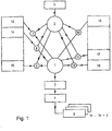
- data or signals 13 to 18 which are filtered by a plurality of keys 7 to 12 and which are characteristic of the operating states of a CNC machine tool are fed to an observer module 1.
- the keys or filters 7 to 12 are determined by a configurator module 2 so that they are related in time and / or function to the events and faults relevant to the operation of the machine.
- the observer module 1 feeds the data associated with the keys to a memory module 3.
- the memory module 3 can be queried with an evaluation module 4 for evaluating the data.
- the configurator module 2 is fed by a configuration file 5, in which monitoring criteria are included, so that the configurator module 2 can define the keys 7 to 12 in such a way that signals or data to be recorded from the operation of the CNC machine tool are dependent on their type, their content , their functional or temporal relationship to other events.
- identification cards 6 can be created in which data records are recorded. In addition to quality assurance, this also enables long-term diagnoses by regularly repeating the production of identification cards with subsequent comparison. This enables criteria to be found for an early warning system for preventive or event-driven maintenance planning.
- the configurator module 2 determines the keys on the basis of Boolean logic rules (AND, OR, NOT, etc.). Alternatively, fuzzy logic rules can also be implemented.
- the keys 7 to 12 in FIG. 1 are each applied to an analog or digital operating state of the machine before they are fed to the observer module 1. However, since the keys or filters 7 to 12 can also be determined depending on one another, it is also possible to record events with complex requirements and to feed them to the observer module 1.
- the data form and the temporal assignment of the filtered data or signals for storage in the memory module 3 are organized in the observer module 1. When the data is saved, a time value is also stored, so that an analysis at a later time in comparison to other data (and their time value) is possible.
- the individual operating states (inputs / outputs, contents of memory cells, data, commands, etc.) of the CNC machine tool are recorded, filtered and possibly stored together with a time stamp by the diagnostic device according to the invention in a predetermined time grid (for example, of a few milliseconds) .
- a time grid for example, of a few milliseconds.
- data from different priority levels can also be assigned to one another and evaluated in a time-correlated manner.
- all analog processes can also be recorded, filtered, and assigned to the corresponding digital data and saved in time.
- the memory module 3 is organized as a FIFO memory, so that the longest time data is deleted.
- the diagnostic device is implemented in the control of the CNC machine tool in that the individual functions are present in each task of the control software or can be called up during the processing of each task.
- a separate diagnostic module is added to each task of the usual control program, which ensures data acquisition, data selection and storage with the time stamp. Since each individual task of the control program has this function, data acquisition can be carried out done in real time.
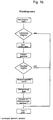
- the program flow chart of the respective diagnostic model is illustrated in Fig. 1c.
- the associated diagnostic module is called.
- the monitoring criteria are read out of the configuration file 5 and the keys are generated therefrom.
- the data generated in the respective task is then linked to the generated keys and it is determined whether relevant data are to be recorded.
- the observer module provides the data to be recorded with the current time stamp and stores this data together with the time stamp.
- the diagnostic module can also be called up and processed (several times) while a task is being processed. This can either be interrupt-controlled or by program-controlled calls to the diagnostic module in the course of the respective task. The time interval between two calls to the diagnostics module of each task is so short that it is ensured that all relevant events in the process are recorded.
- the keys can also be generated as part of an initialization, so that this does not have to take place during the program run (in real time).
- the configuration file 5 specifies in which area of the NC program the observer module 1 should be active. In addition, the time grid of the data acquisition (and thus also the recording speed) is determined. Furthermore, the criteria that must be met for the recording to start must be specified. As an example, the speed of the C-axis should be monitored and recorded if the speed deviates by a tolerance value (&& Limit) below a certain limit (100 revolutions / min).
- the configuration file 5 contains information which enables the configurator module 2 to generate keys or filters in order to extract from the entirety of those in the CNC machine tool and the data generated by the controller to save and extract the necessary and sufficient data from the function modules and their temporal relationship for the present application: current consumption of the C-axis, speed of the C-axis, temperature of the C-axis and digital control signals for the C -Axis.
- the configuration file will contain a program with the following function:
- This program function becomes active as soon as command G0 C0 (start C-axis) is reached in the NC program of the machine.
- the time interval between two queries is determined by the time TI.
- Fig. 3 shows a menu SETUP "SELECTION".
- the menu offers a setting aid for the diagnosis of different machine functions.
- Trigger pre-assignments for the SETUP "SAVE" menu are loaded from an internal memory of the electronic control of the CNC machine tool. Corresponding reference curves are available in a memory.
- the SETUP data is then saved under a specific file name (e.g. test 1).
- FIG. 4 shows in a schematic manner how data acquired and stored together with the respective time stamp are displayed at a later point in time.
- the individual data from the trigger time T1, T2, T3 are displayed.
- the data 1 can be the course of the digital signal MY2E
- the data 2 the speed course of the motor of the C-axis
- the data 3 can be another signal that is only acquired at a later point in time.
- the data of a signal curve are displayed along the time axis according to their respective time mark and the individual signal curves are thus correlated with one another.
- FIG. 5 shows a screen representation of the reproduction of the data which have been acquired in accordance with the diagnostic example from FIG. 2.
- digital signal profiles MY2E, MY2F are also illustrated.
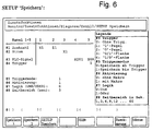
- FIG. 6 shows a menu SETUP "SAVE”. Various data can be selected in the parameters.
- the speed can be recorded for the following axes and spindles: X1, X2, Z1, Z2, Z3, V1, Y1, S1, S2, S3, S4.
- the current can be recorded for the following axes and spindles: X1, X2, Z1, Z2, Z3, V1, Y1, S1, S2, S3, S4.
- trigger conditions can be linked by a logical "AND” or “OR”. If the trigger condition is fulfilled, all data set in # 1 to # 3 are recorded.
- a macro means that the diagnosis is activated via the macro G309 and thus the possibility of synchronization with the NC program. However, the recording only starts from the G309 macro and when the trigger conditions of # 4 are fulfilled.
- time ranges or time intervals can be selected for recording: 1s, 3s, 6s, 9s, 12s, ... 60s.
Applications Claiming Priority (2)
| Application Number | Priority Date | Filing Date | Title |
|---|---|---|---|
| DE19617620A DE19617620A1 (de) | 1996-05-02 | 1996-05-02 | Diagnoseeinrichtung |
| DE19617620 | 1996-05-02 |
Publications (2)
| Publication Number | Publication Date |
|---|---|
| EP0805382A1 true EP0805382A1 (fr) | 1997-11-05 |
| EP0805382B1 EP0805382B1 (fr) | 1999-10-27 |
Family
ID=7793122
Family Applications (1)
| Application Number | Title | Priority Date | Filing Date |
|---|---|---|---|
| EP97107317A Expired - Lifetime EP0805382B1 (fr) | 1996-05-02 | 1997-05-02 | Dispositif de diagnostique pour une machine à commande électronique avec clés de combinaison d'états mesurés de la machine |
Country Status (3)
| Country | Link |
|---|---|
| EP (1) | EP0805382B1 (fr) |
| AT (1) | ATE186129T1 (fr) |
| DE (2) | DE19617620A1 (fr) |
Cited By (5)
| Publication number | Priority date | Publication date | Assignee | Title |
|---|---|---|---|---|
| WO1999044106A1 (fr) * | 1998-02-27 | 1999-09-02 | MTU MOTOREN- UND TURBINEN-UNION MüNCHEN GMBH | Systeme et procede pour le diagnostic d'etats de groupes motopropulseurs |
| DE102005025673A1 (de) * | 2005-06-03 | 2006-12-14 | Siemens Ag | Betriebsverfahren für eine Auswertungseinrichtung für eine Produktionsmaschine |
| DE19937515B4 (de) * | 1999-08-09 | 2008-12-24 | Abb Ag | Verfahren und Anordnung zur selektiven Aufzeichnung von Meldungen |
| US9310795B2 (en) | 2008-11-25 | 2016-04-12 | Pilz Gmbh & Co. Kg | Safety controller and method for controlling an automated installation |
| CN113614654A (zh) * | 2019-03-19 | 2021-11-05 | 西门子股份公司 | 安全相关的诊断消息 |
Families Citing this family (4)
| Publication number | Priority date | Publication date | Assignee | Title |
|---|---|---|---|---|
| US6515665B1 (en) * | 1999-06-21 | 2003-02-04 | Tektronix, Inc. | Data filtering/suppression of data acquisitions/samples for multi-channel electronic display and analysis |
| JP3834307B2 (ja) | 2003-09-29 | 2006-10-18 | ファナック株式会社 | ロボットシステム |
| DE102010002183B4 (de) | 2010-02-22 | 2013-01-10 | Koenig & Bauer Aktiengesellschaft | Verfahren zur Durchführung in einer Druckmaschine mit mindestens einer Maschineneinheit und mit mehreren Antrieben |
| DE102022120738A1 (de) | 2022-08-17 | 2024-02-22 | TRUMPF Werkzeugmaschinen SE + Co. KG | Verfahren und System zur Bestimmung eines Betriebszustandes einer Werkzeugmaschine |
Citations (2)
| Publication number | Priority date | Publication date | Assignee | Title |
|---|---|---|---|---|
| US3795916A (en) * | 1969-11-14 | 1974-03-05 | Westinghouse Electric Corp | Process operation error monitor and error message system |
| EP0418787A2 (fr) * | 1989-09-19 | 1991-03-27 | Siemens Aktiengesellschaft | Procédé de contrôle d'activité d'une machine-outil |
Family Cites Families (4)
| Publication number | Priority date | Publication date | Assignee | Title |
|---|---|---|---|---|
| GB2104685B (en) * | 1981-08-24 | 1985-12-18 | Omron Tateisi Electronics Co | Programmable controller |
| JPS59154321A (ja) * | 1983-02-22 | 1984-09-03 | Toshiba Mach Co Ltd | モニタリングデ−タ表示装置 |
| JPH0670764B2 (ja) * | 1985-03-06 | 1994-09-07 | 株式会社日立製作所 | シ−ケンス制御装置 |
| DE4408603A1 (de) * | 1994-03-08 | 1995-09-14 | Mannesmann Ag | Verfahren zur Erhöhung der Sicherheit in hierarchisch strukturierten Automatisierungssystemen |
-
1996
- 1996-05-02 DE DE19617620A patent/DE19617620A1/de not_active Withdrawn
-
1997
- 1997-05-02 DE DE59700609T patent/DE59700609D1/de not_active Expired - Lifetime
- 1997-05-02 EP EP97107317A patent/EP0805382B1/fr not_active Expired - Lifetime
- 1997-05-02 AT AT97107317T patent/ATE186129T1/de not_active IP Right Cessation
Patent Citations (2)
| Publication number | Priority date | Publication date | Assignee | Title |
|---|---|---|---|---|
| US3795916A (en) * | 1969-11-14 | 1974-03-05 | Westinghouse Electric Corp | Process operation error monitor and error message system |
| EP0418787A2 (fr) * | 1989-09-19 | 1991-03-27 | Siemens Aktiengesellschaft | Procédé de contrôle d'activité d'une machine-outil |
Cited By (7)
| Publication number | Priority date | Publication date | Assignee | Title |
|---|---|---|---|---|
| WO1999044106A1 (fr) * | 1998-02-27 | 1999-09-02 | MTU MOTOREN- UND TURBINEN-UNION MüNCHEN GMBH | Systeme et procede pour le diagnostic d'etats de groupes motopropulseurs |
| DE19808197C2 (de) * | 1998-02-27 | 2001-08-09 | Mtu Aero Engines Gmbh | System und Verfahren zur Diagnose von Triebwerkszuständen |
| US6574613B1 (en) | 1998-02-27 | 2003-06-03 | Jorge Moreno-Barragan | System and method for diagnosing jet engine conditions |
| DE19937515B4 (de) * | 1999-08-09 | 2008-12-24 | Abb Ag | Verfahren und Anordnung zur selektiven Aufzeichnung von Meldungen |
| DE102005025673A1 (de) * | 2005-06-03 | 2006-12-14 | Siemens Ag | Betriebsverfahren für eine Auswertungseinrichtung für eine Produktionsmaschine |
| US9310795B2 (en) | 2008-11-25 | 2016-04-12 | Pilz Gmbh & Co. Kg | Safety controller and method for controlling an automated installation |
| CN113614654A (zh) * | 2019-03-19 | 2021-11-05 | 西门子股份公司 | 安全相关的诊断消息 |
Also Published As
| Publication number | Publication date |
|---|---|
| ATE186129T1 (de) | 1999-11-15 |
| DE59700609D1 (de) | 1999-12-02 |
| EP0805382B1 (fr) | 1999-10-27 |
| DE19617620A1 (de) | 1997-11-13 |
Similar Documents
| Publication | Publication Date | Title |
|---|---|---|
| EP2419799A1 (fr) | Procédé de préparation de données d'état de processus et/ou de données d'état de machine d'une machine-outil | |
| EP2095336A1 (fr) | Procédé de consignation des erreurs pour une installation de revêtement | |
| EP2356527B1 (fr) | Commande de sécurité et procédé pour commander une installation automatisée comprenant une pluralité de composants matériels | |
| EP1296207B1 (fr) | Appareil HMI et procédé de commande d'une installation technique, système d'automatisation avec cet appareil HMI et produit de programme informatique avec un programme pour la mise en oeuvre de ce procédé dans un appareil HMI ou dans un système d'automatisation | |
| EP1738185B1 (fr) | Dispositif de traitement de signaux avec declenchement synchron | |
| DE4406723B4 (de) | Verfahren zur Überwachung des Betriebszustands einer Maschine oder Anlage | |
| EP0805382B1 (fr) | Dispositif de diagnostique pour une machine à commande électronique avec clés de combinaison d'états mesurés de la machine | |
| DE102005041632A1 (de) | Verfahren und Vorrichtung zur Überwachung einer technischen Einrichtung | |
| EP2419798A1 (fr) | Procédé permettant d'obtenir une information concernant l'usure d'un composant d'une machine et procédé de préparation d'un algorithme alternatif | |
| DE60212376T2 (de) | System zur vorsehbaren diagnose in einer speicher programmierbaren steuerung | |
| DE2729408C2 (de) | Rechnergeführte numerische Steueranordnung für eine Werkzeugmaschine | |
| DE2729372A1 (de) | Ueberwachungsverfahren fuer eine numerisch gesteuerte werkzeugmaschine | |
| DE19815647C2 (de) | Verfahren zur Synchronisation einer lokalen auf eine zentrale Zeitbasis, und Vorrichtung zur Durchführung des Verfahrens mit bevorzugten Verwendungen | |
| EP1269358A1 (fr) | Systeme et procede pour saisir et memoriser des donnees d'une installation de production | |
| DE3606518A1 (de) | Verfahren zur erfassung und meldung von fehlern und ursachen fuer stoerungen im ablauf von durch automatisierungsmittel gesteuerten oder geregelten prozessen | |
| EP1117023B1 (fr) | Dispositif de diagnostic de fautes pendant le fonctionnement d'un véhicule automobile | |
| DE3413330A1 (de) | Verfahren zur ueberwachung und lokalisierung eines fehlers der fabrikationszyklen einer automatischen fertigungsstrasse und vorrichtung zu seiner durchfuehrung | |
| DE10115897C2 (de) | Verfahren und Vorrichtung zur Bereitstellung von Informationen für die Analyse von Fehlern bei einer technischen Anlage | |
| EP3598250B1 (fr) | Système de détection | |
| WO2009000422A2 (fr) | Procédé et dispositif pour surveiller une installation technique | |
| EP1079289A2 (fr) | Unité de projection pour des blocs de données correspondant d'un système avec une unité de commande et une unité d'opération et/ou supervision et système muni de moyens pour comparer des versions de blocs de données de diagnostic | |
| EP1335491B1 (fr) | Circuit anti-rebond de signal | |
| EP4246261A1 (fr) | Système de commande pour une installation technique et procédé de fonctionnement | |
| DE19805518B4 (de) | Verfahren und Vorrichtung zur Analyse von Schutzsignalen für eine Anzahl von sicherheitsrelevanten Anlagenteilen einer technischen Anlage | |
| DE102007027262A1 (de) | Aktionsmodule für zustandsabhängige Wartungsarbeiten |
Legal Events
| Date | Code | Title | Description |
|---|---|---|---|
| PUAI | Public reference made under article 153(3) epc to a published international application that has entered the european phase |
Free format text: ORIGINAL CODE: 0009012 |
|
| AK | Designated contracting states |
Kind code of ref document: A1 Designated state(s): AT CH DE FR GB IT LI SE |
|
| 17P | Request for examination filed |
Effective date: 19971121 |
|
| 17Q | First examination report despatched |
Effective date: 19980127 |
|
| GRAG | Despatch of communication of intention to grant |
Free format text: ORIGINAL CODE: EPIDOS AGRA |
|
| GRAG | Despatch of communication of intention to grant |
Free format text: ORIGINAL CODE: EPIDOS AGRA |
|
| GRAG | Despatch of communication of intention to grant |
Free format text: ORIGINAL CODE: EPIDOS AGRA |
|
| GRAH | Despatch of communication of intention to grant a patent |
Free format text: ORIGINAL CODE: EPIDOS IGRA |
|
| GRAH | Despatch of communication of intention to grant a patent |
Free format text: ORIGINAL CODE: EPIDOS IGRA |
|
| GRAA | (expected) grant |
Free format text: ORIGINAL CODE: 0009210 |
|
| ITF | It: translation for a ep patent filed |
Owner name: BARZANO' E ZANARDO MILANO S.P.A. |
|
| AK | Designated contracting states |
Kind code of ref document: B1 Designated state(s): AT CH DE FR GB IT LI SE |
|
| REF | Corresponds to: |
Ref document number: 186129 Country of ref document: AT Date of ref document: 19991115 Kind code of ref document: T |
|
| REG | Reference to a national code |
Ref country code: CH Ref legal event code: EP |
|
| GBT | Gb: translation of ep patent filed (gb section 77(6)(a)/1977) |
Effective date: 19991028 |
|
| REF | Corresponds to: |
Ref document number: 59700609 Country of ref document: DE Date of ref document: 19991202 |
|
| ET | Fr: translation filed | ||
| PLBE | No opposition filed within time limit |
Free format text: ORIGINAL CODE: 0009261 |
|
| STAA | Information on the status of an ep patent application or granted ep patent |
Free format text: STATUS: NO OPPOSITION FILED WITHIN TIME LIMIT |
|
| 26N | No opposition filed | ||
| REG | Reference to a national code |
Ref country code: GB Ref legal event code: IF02 |
|
| PGFP | Annual fee paid to national office [announced via postgrant information from national office to epo] |
Ref country code: SE Payment date: 20070522 Year of fee payment: 11 Ref country code: AT Payment date: 20070522 Year of fee payment: 11 |
|
| PGFP | Annual fee paid to national office [announced via postgrant information from national office to epo] |
Ref country code: GB Payment date: 20080515 Year of fee payment: 12 |
|
| PG25 | Lapsed in a contracting state [announced via postgrant information from national office to epo] |
Ref country code: AT Free format text: LAPSE BECAUSE OF NON-PAYMENT OF DUE FEES Effective date: 20080502 |
|
| GBPC | Gb: european patent ceased through non-payment of renewal fee |
Effective date: 20090502 |
|
| PG25 | Lapsed in a contracting state [announced via postgrant information from national office to epo] |
Ref country code: GB Free format text: LAPSE BECAUSE OF NON-PAYMENT OF DUE FEES Effective date: 20090502 |
|
| PG25 | Lapsed in a contracting state [announced via postgrant information from national office to epo] |
Ref country code: SE Free format text: LAPSE BECAUSE OF NON-PAYMENT OF DUE FEES Effective date: 20080503 |
|
| PGFP | Annual fee paid to national office [announced via postgrant information from national office to epo] |
Ref country code: CH Payment date: 20140519 Year of fee payment: 18 Ref country code: IT Payment date: 20140520 Year of fee payment: 18 Ref country code: DE Payment date: 20140528 Year of fee payment: 18 |
|
| PGFP | Annual fee paid to national office [announced via postgrant information from national office to epo] |
Ref country code: FR Payment date: 20140528 Year of fee payment: 18 |
|
| REG | Reference to a national code |
Ref country code: DE Ref legal event code: R119 Ref document number: 59700609 Country of ref document: DE |
|
| REG | Reference to a national code |
Ref country code: CH Ref legal event code: PL |
|
| PG25 | Lapsed in a contracting state [announced via postgrant information from national office to epo] |
Ref country code: LI Free format text: LAPSE BECAUSE OF NON-PAYMENT OF DUE FEES Effective date: 20150531 Ref country code: CH Free format text: LAPSE BECAUSE OF NON-PAYMENT OF DUE FEES Effective date: 20150531 Ref country code: IT Free format text: LAPSE BECAUSE OF NON-PAYMENT OF DUE FEES Effective date: 20150502 |
|
| REG | Reference to a national code |
Ref country code: FR Ref legal event code: ST Effective date: 20160129 |
|
| PG25 | Lapsed in a contracting state [announced via postgrant information from national office to epo] |
Ref country code: DE Free format text: LAPSE BECAUSE OF NON-PAYMENT OF DUE FEES Effective date: 20151201 |
|
| PG25 | Lapsed in a contracting state [announced via postgrant information from national office to epo] |
Ref country code: FR Free format text: LAPSE BECAUSE OF NON-PAYMENT OF DUE FEES Effective date: 20150601 |