EP0805382A1 - Diagnostic apparatus for an electronically controlled machine in which detected operating conditions are combined according to keys - Google Patents
Diagnostic apparatus for an electronically controlled machine in which detected operating conditions are combined according to keys Download PDFInfo
- Publication number
- EP0805382A1 EP0805382A1 EP97107317A EP97107317A EP0805382A1 EP 0805382 A1 EP0805382 A1 EP 0805382A1 EP 97107317 A EP97107317 A EP 97107317A EP 97107317 A EP97107317 A EP 97107317A EP 0805382 A1 EP0805382 A1 EP 0805382A1
- Authority
- EP
- European Patent Office
- Prior art keywords
- machine
- diagnostic device
- module
- keys
- events
- Prior art date
- Legal status (The legal status is an assumption and is not a legal conclusion. Google has not performed a legal analysis and makes no representation as to the accuracy of the status listed.)
- Granted
Links
- 238000004519 manufacturing process Methods 0.000 claims description 13
- 238000011156 evaluation Methods 0.000 claims description 12
- 230000006870 function Effects 0.000 claims description 12
- 230000002123 temporal effect Effects 0.000 claims description 10
- 230000005540 biological transmission Effects 0.000 claims description 6
- 238000012544 monitoring process Methods 0.000 claims description 5
- 238000013528 artificial neural network Methods 0.000 claims 1
- 230000000875 corresponding effect Effects 0.000 description 8
- 238000003745 diagnosis Methods 0.000 description 7
- 238000000034 method Methods 0.000 description 7
- 230000007257 malfunction Effects 0.000 description 5
- 230000008569 process Effects 0.000 description 5
- 230000007774 longterm Effects 0.000 description 4
- 238000012423 maintenance Methods 0.000 description 3
- 238000013024 troubleshooting Methods 0.000 description 3
- 102220580939 Induced myeloid leukemia cell differentiation protein Mcl-1_Y57F_mutation Human genes 0.000 description 2
- 230000004913 activation Effects 0.000 description 2
- 230000008901 benefit Effects 0.000 description 2
- 238000012217 deletion Methods 0.000 description 2
- 230000037430 deletion Effects 0.000 description 2
- 230000001419 dependent effect Effects 0.000 description 2
- 238000001514 detection method Methods 0.000 description 2
- 230000002452 interceptive effect Effects 0.000 description 2
- 230000004807 localization Effects 0.000 description 2
- 238000005259 measurement Methods 0.000 description 2
- 230000003449 preventive effect Effects 0.000 description 2
- 238000012545 processing Methods 0.000 description 2
- 230000002730 additional effect Effects 0.000 description 1
- 238000013459 approach Methods 0.000 description 1
- 230000006399 behavior Effects 0.000 description 1
- 239000000969 carrier Substances 0.000 description 1
- 230000008859 change Effects 0.000 description 1
- 238000007796 conventional method Methods 0.000 description 1
- 230000002596 correlated effect Effects 0.000 description 1
- 238000010586 diagram Methods 0.000 description 1
- 230000008030 elimination Effects 0.000 description 1
- 238000003379 elimination reaction Methods 0.000 description 1
- 230000007246 mechanism Effects 0.000 description 1
- 238000004886 process control Methods 0.000 description 1
- 238000000275 quality assurance Methods 0.000 description 1
- 230000009467 reduction Effects 0.000 description 1
- 230000011664 signaling Effects 0.000 description 1
- 238000007619 statistical method Methods 0.000 description 1
- 230000001360 synchronised effect Effects 0.000 description 1
- 238000012360 testing method Methods 0.000 description 1
Images


Classifications
-
- G—PHYSICS
- G05—CONTROLLING; REGULATING
- G05B—CONTROL OR REGULATING SYSTEMS IN GENERAL; FUNCTIONAL ELEMENTS OF SUCH SYSTEMS; MONITORING OR TESTING ARRANGEMENTS FOR SUCH SYSTEMS OR ELEMENTS
- G05B19/00—Programme-control systems
- G05B19/02—Programme-control systems electric
- G05B19/18—Numerical control [NC], i.e. automatically operating machines, in particular machine tools, e.g. in a manufacturing environment, so as to execute positioning, movement or co-ordinated operations by means of programme data in numerical form
- G05B19/406—Numerical control [NC], i.e. automatically operating machines, in particular machine tools, e.g. in a manufacturing environment, so as to execute positioning, movement or co-ordinated operations by means of programme data in numerical form characterised by monitoring or safety
-
- G—PHYSICS
- G05—CONTROLLING; REGULATING
- G05B—CONTROL OR REGULATING SYSTEMS IN GENERAL; FUNCTIONAL ELEMENTS OF SUCH SYSTEMS; MONITORING OR TESTING ARRANGEMENTS FOR SUCH SYSTEMS OR ELEMENTS
- G05B2219/00—Program-control systems
- G05B2219/30—Nc systems
- G05B2219/33—Director till display
- G05B2219/33287—Program panel to program, enter data for diagnostic
-
- G—PHYSICS
- G05—CONTROLLING; REGULATING
- G05B—CONTROL OR REGULATING SYSTEMS IN GENERAL; FUNCTIONAL ELEMENTS OF SUCH SYSTEMS; MONITORING OR TESTING ARRANGEMENTS FOR SUCH SYSTEMS OR ELEMENTS
- G05B2219/00—Program-control systems
- G05B2219/30—Nc systems
- G05B2219/33—Director till display
- G05B2219/33299—Real time, online diagnostic, integrated in normal control system
-
- G—PHYSICS
- G05—CONTROLLING; REGULATING
- G05B—CONTROL OR REGULATING SYSTEMS IN GENERAL; FUNCTIONAL ELEMENTS OF SUCH SYSTEMS; MONITORING OR TESTING ARRANGEMENTS FOR SUCH SYSTEMS OR ELEMENTS
- G05B2219/00—Program-control systems
- G05B2219/30—Nc systems
- G05B2219/33—Director till display
- G05B2219/33306—Configuration file to set how data will be displayed
-
- G—PHYSICS
- G05—CONTROLLING; REGULATING
- G05B—CONTROL OR REGULATING SYSTEMS IN GENERAL; FUNCTIONAL ELEMENTS OF SUCH SYSTEMS; MONITORING OR TESTING ARRANGEMENTS FOR SUCH SYSTEMS OR ELEMENTS
- G05B2219/00—Program-control systems
- G05B2219/30—Nc systems
- G05B2219/33—Director till display
- G05B2219/33324—What to diagnose, whole system, test, simulate
Definitions
- the present invention relates to a diagnostic device for at least one electronically controlled machine, in particular a CNC machine tool, a flexible manufacturing cell or the like.
- Such machines either have a computer unit, a storage unit, an input unit and an output unit, or they are operationally connected to them.
- the manufacturing accuracy and operational reliability of modern CNC machine tools or flexible manufacturing cells are very high. Malfunctions or deviations from specified manufacturing tolerances therefore occur very rarely, but cannot be excluded. The causes for this are natural wear, approaching process limits or process safety, as well as sporadic errors in individual components of the machine. Malfunctions and failures occur comparatively rarely, but can have a considerable impact on the production process. This is particularly evident in linked manufacturing processes. In addition, economic reasons often prohibit having redundant means of production available. For this reason, the causes of malfunctions and failures must be identified and eliminated as quickly as possible. However, this is very difficult in complex systems with a low frequency of malfunctions and error repetition rates.
- “Online diagnostic means” integrated in the control of the machine can record certain data and make fault conditions visible by displaying critical data on a display while the machine is operating. This can be either the display on individual displays (tachometer, temperature meter, signaling means for exceeding or falling below the range, etc.), or by displaying several (also in relation to each other) measured variables on a common screen. No interventions in the system are required, but sporadic errors can only be found if the correct measured variables have been recorded and observed during the error occurrence. This makes troubleshooting very difficult.
- the object of the invention is to provide a diagnostic device which makes it possible to narrow down and identify sporadically occurring errors or long-term deviations.
- the diagnostic device uses a computer unit, a memory unit, an input unit and an output unit for the solution from, the input unit being connected to transducers which record the analog and / or digital operating states of the machine, convert corresponding signals into these and feed them to the computing unit, the computing unit links the signals added to them with predetermined keys and the linking results of the storage unit and / or the output unit feeds, and wherein the operating states can be detected at time intervals, which ensures that events and / or faults relevant to the operation of the machine are converted into corresponding signals and fed to the computer unit.
- the invention is based on the knowledge that both digital states (input / output signals, contents of memory cells, data, commands transmitted within the machine control system) and analog signals (current, voltage, speed, temperature, forces, etc.) .) to be recorded.
- digital states input / output signals, contents of memory cells, data, commands transmitted within the machine control system
- analog signals current, voltage, speed, temperature, forces, etc.
- all states in the machine and / or variables occurring in its control could be recorded. However, since this is not feasible with reasonable effort and not all sizes are relevant, only certain sizes are recorded and evaluated. These are quantities that can be the cause of an error.
- the relevant variables or the signals that represent them are linked and placed in a functional and / or temporal context. The keys thus act as a filter in order to achieve a (further) reduction in the detected operating states of the machine, that is to say the analog and / or digital variables.
- the sizes selected by the key or filter are stored without interfering with the structure of the CNC machine tool or its electronic control.
- the data recording is organized in such a way that the type, content, temporal and functional relationship as well as the interdependencies of the individual sizes can be configured by simple parameter specification. Changes in the system or its structure are therefore not necessary. Rather, built-in mechanisms are activated. If the recorded quantities are provided with a time stamp before or after the combination with the keys, which reflects their time of acquisition, the quantity added in this way can also be clearly evaluated and added later other sizes in terms of time and function. The analysis can thus take place off-line, while the acquisition takes place in real time (on-line).
- control unit in modern CNC machines has a process computer, individual control tasks are processed in real time by dividing them into individual tasks, preferably with graded priority.
- a task with the highest priority level can link the data and measured variables arising in tasks with a lower priority with the respective keys, provide them with time values and save them. The required key can then be used to select the relevant data.
- the filters or keys can have a very complex structure, so that the error state can be represented and identified by the smallest possible volume of data.
- Error-relevant events and / or faults are preferably recorded simultaneously for the operation of the machine.
- a selection, temporal and functional assignment can then be achieved by linking to the keys. If the recording of the analog and / or digital operating states of the machine takes place in real time and also analog and digital quantities are recorded synchronously and time stamps are carried along, it is possible to carry out the evaluation, storage and display one after the other, if necessary, without the time assignment of signals and the possibility of one corresponding subsequent evaluation is lost. This also reduces the computing capacity required.
- the keys or filters are preferably defined in such a way that they are temporally and functionally related to the events and / or faults relevant to the operation of the machine. It is thus possible to control the point in time and the duration of the data recording by means of variables occurring in the manufacturing process.
- the sensors record events and / or faults relevant to the operation of the machine in synchronism with actuation signals occurring in the machine for actuators or operating resources of the machine. Since an electronically controlled machine, for example a CNC machine tool, works clock-controlled, interfering signals falling between the clock intervals, which are shorter than individual clock intervals, can have practically no influence on the process control. If faults persist for so long that they fall within an active clock interval, they are also recorded and can be evaluated and localized.
- the sensors detect events and / or faults in the electronic control of the machine, the machine itself or other devices that are operationally connected to the machine or its electronic control and are relevant to the operation of the machine. This applies in particular to components of linked systems.
- the diagnostic device preferably has an observer module that monitors a manufacturing process, a configurator module that defines the keys, a result storage module, and an evaluation module.
- the observer module can monitor all control data in a time-controlled or event-controlled manner.
- the configurator module can create the keys or filters depending on a configuration file containing monitoring criteria. Because the storage capacity of the result storage module is not unlimited records that are longest in time without an error occurring during this period are deleted.
- the memory is preferably organized as a first-in-first-out (FIFO) memory.
- a permanent storage medium disk, diskette or the like
- the deletion of data from the memory can also take place depending on other criteria (change within successive data records, completed manufacturing section or the like).
- the evaluation module can display operating states, events and / or faults relevant to the operation of the machine, as well as results of links with keys, so that the temporal relationship can be restored and displayed (visualized) synchronously. Furthermore, maps (maps) of states can be created and saved with tolerance windows (on data carriers or via remote transmission), so that wear trends can be monitored over longer periods of time using statistical methods and the approach to limits can be determined. Preventive maintenance measures and maintenance planning can then be derived from this at an early stage.
- Equipment in the electronic control of the machine is preferably used to implement the components: result storage module, evaluation module, and / or observer module. This has the advantage that less hardware is required on the one hand. On the other hand, a closed and uniform implementation of the overall system is possible. This makes troubleshooting easier. As an alternative to this, a separate implementation can also be carried out for machines whose electronic control does not allow this for various reasons. in separate hardware, which are then connected to each other via correspondingly powerful data channels (e.g. BUS systems) and associated drivers.
- correspondingly powerful data channels e.g. BUS systems
- Operating states, events and / or faults relevant to the operation of the machine are preferably dependent of respective analog or digital signal levels and / or signal edges.
- the evaluation or the configuration of the keys or filters takes place on the basis of Boolean logic rules or fuzzy logic rules.
- the configurator module defines the keys or filters so that signals to be recorded are determined depending on their type, their content, their functional or temporal relationship to other events in the machine, or in other devices connected to the machine.
- the configurator module determines the keys so that digital and associated analog signals to be recorded are recorded simultaneously.
- search key the invention allows time-related search and analysis of events in CNC machines.
- the resources required to implement the diagnostic device can be activated without changing the structure of the machine control, since they are preferably integrated in the electronic control of the machine.
- sporadic errors can also be diagnosed by remote transmission. This is not feasible with conventional methods, since remote transmission devices operate according to their time interval controls, which in any case are asynchronous to the time control of the CNC computer and are certainly slower. However, since the data also carries its "time stamp" information ("stamped it"), the chronologically synchronous reference can be reconstructed at any time.
- data or signals 13 to 18 which are filtered by a plurality of keys 7 to 12 and which are characteristic of the operating states of a CNC machine tool are fed to an observer module 1.
- the keys or filters 7 to 12 are determined by a configurator module 2 so that they are related in time and / or function to the events and faults relevant to the operation of the machine.
- the observer module 1 feeds the data associated with the keys to a memory module 3.
- the memory module 3 can be queried with an evaluation module 4 for evaluating the data.
- the configurator module 2 is fed by a configuration file 5, in which monitoring criteria are included, so that the configurator module 2 can define the keys 7 to 12 in such a way that signals or data to be recorded from the operation of the CNC machine tool are dependent on their type, their content , their functional or temporal relationship to other events.
- identification cards 6 can be created in which data records are recorded. In addition to quality assurance, this also enables long-term diagnoses by regularly repeating the production of identification cards with subsequent comparison. This enables criteria to be found for an early warning system for preventive or event-driven maintenance planning.
- the configurator module 2 determines the keys on the basis of Boolean logic rules (AND, OR, NOT, etc.). Alternatively, fuzzy logic rules can also be implemented.
- the keys 7 to 12 in FIG. 1 are each applied to an analog or digital operating state of the machine before they are fed to the observer module 1. However, since the keys or filters 7 to 12 can also be determined depending on one another, it is also possible to record events with complex requirements and to feed them to the observer module 1.
- the data form and the temporal assignment of the filtered data or signals for storage in the memory module 3 are organized in the observer module 1. When the data is saved, a time value is also stored, so that an analysis at a later time in comparison to other data (and their time value) is possible.
- the individual operating states (inputs / outputs, contents of memory cells, data, commands, etc.) of the CNC machine tool are recorded, filtered and possibly stored together with a time stamp by the diagnostic device according to the invention in a predetermined time grid (for example, of a few milliseconds) .
- a time grid for example, of a few milliseconds.
- data from different priority levels can also be assigned to one another and evaluated in a time-correlated manner.
- all analog processes can also be recorded, filtered, and assigned to the corresponding digital data and saved in time.
- the memory module 3 is organized as a FIFO memory, so that the longest time data is deleted.
- the diagnostic device is implemented in the control of the CNC machine tool in that the individual functions are present in each task of the control software or can be called up during the processing of each task.
- a separate diagnostic module is added to each task of the usual control program, which ensures data acquisition, data selection and storage with the time stamp. Since each individual task of the control program has this function, data acquisition can be carried out done in real time.
- the program flow chart of the respective diagnostic model is illustrated in Fig. 1c.
- the associated diagnostic module is called.
- the monitoring criteria are read out of the configuration file 5 and the keys are generated therefrom.
- the data generated in the respective task is then linked to the generated keys and it is determined whether relevant data are to be recorded.
- the observer module provides the data to be recorded with the current time stamp and stores this data together with the time stamp.
- the diagnostic module can also be called up and processed (several times) while a task is being processed. This can either be interrupt-controlled or by program-controlled calls to the diagnostic module in the course of the respective task. The time interval between two calls to the diagnostics module of each task is so short that it is ensured that all relevant events in the process are recorded.
- the keys can also be generated as part of an initialization, so that this does not have to take place during the program run (in real time).
- the configuration file 5 specifies in which area of the NC program the observer module 1 should be active. In addition, the time grid of the data acquisition (and thus also the recording speed) is determined. Furthermore, the criteria that must be met for the recording to start must be specified. As an example, the speed of the C-axis should be monitored and recorded if the speed deviates by a tolerance value (&& Limit) below a certain limit (100 revolutions / min).
- the configuration file 5 contains information which enables the configurator module 2 to generate keys or filters in order to extract from the entirety of those in the CNC machine tool and the data generated by the controller to save and extract the necessary and sufficient data from the function modules and their temporal relationship for the present application: current consumption of the C-axis, speed of the C-axis, temperature of the C-axis and digital control signals for the C -Axis.
- the configuration file will contain a program with the following function:
- This program function becomes active as soon as command G0 C0 (start C-axis) is reached in the NC program of the machine.
- the time interval between two queries is determined by the time TI.
- Fig. 3 shows a menu SETUP "SELECTION".
- the menu offers a setting aid for the diagnosis of different machine functions.
- Trigger pre-assignments for the SETUP "SAVE" menu are loaded from an internal memory of the electronic control of the CNC machine tool. Corresponding reference curves are available in a memory.
- the SETUP data is then saved under a specific file name (e.g. test 1).
- FIG. 4 shows in a schematic manner how data acquired and stored together with the respective time stamp are displayed at a later point in time.
- the individual data from the trigger time T1, T2, T3 are displayed.
- the data 1 can be the course of the digital signal MY2E
- the data 2 the speed course of the motor of the C-axis
- the data 3 can be another signal that is only acquired at a later point in time.
- the data of a signal curve are displayed along the time axis according to their respective time mark and the individual signal curves are thus correlated with one another.
- FIG. 5 shows a screen representation of the reproduction of the data which have been acquired in accordance with the diagnostic example from FIG. 2.
- digital signal profiles MY2E, MY2F are also illustrated.
- FIG. 6 shows a menu SETUP "SAVE”. Various data can be selected in the parameters.
- the speed can be recorded for the following axes and spindles: X1, X2, Z1, Z2, Z3, V1, Y1, S1, S2, S3, S4.
- the current can be recorded for the following axes and spindles: X1, X2, Z1, Z2, Z3, V1, Y1, S1, S2, S3, S4.
- trigger conditions can be linked by a logical "AND” or “OR”. If the trigger condition is fulfilled, all data set in # 1 to # 3 are recorded.
- a macro means that the diagnosis is activated via the macro G309 and thus the possibility of synchronization with the NC program. However, the recording only starts from the G309 macro and when the trigger conditions of # 4 are fulfilled.
- time ranges or time intervals can be selected for recording: 1s, 3s, 6s, 9s, 12s, ... 60s.
Landscapes
- Engineering & Computer Science (AREA)
- Human Computer Interaction (AREA)
- Manufacturing & Machinery (AREA)
- Physics & Mathematics (AREA)
- General Physics & Mathematics (AREA)
- Automation & Control Theory (AREA)
- Testing And Monitoring For Control Systems (AREA)
- Control Or Security For Electrophotography (AREA)
Abstract
Description
Die vorliegende Erfindung betrifft eine Diagnoseeinrichtung für wenigstens eine elektronisch gesteuerte Maschine, insbesondere eine CNC-Werkzeugmaschine, eine flexible Fertigungszelle oder dergl.The present invention relates to a diagnostic device for at least one electronically controlled machine, in particular a CNC machine tool, a flexible manufacturing cell or the like.
Derartige Maschinen haben entweder eine Rechnereinheit, eine Speichereinheit, eine Eingabeeinheit und eine Ausgabeeinheit, oder sie sind damit betrieblich verbunden. Die Herstellungsgenauigkeit und die Betriebszuverlässigkeit moderner CNC-Werkzeugmaschinen oder flexibler Fertigungszellen sind sehr hoch. Betriebsstörungen oder Abweichung von vorgegebenen Fertigungstoleranzen treten daher sehr selten auf, können jedoch nicht ausgeschlossen werden. Ursachen hierfür sind natürlicher Verschleiß, Annäherung an Prozeßgrenzen oder Prozeßsicherheit, sowie sporadische Fehler in einzelnen Komponenten der Maschine. Störungen und Ausfälle kommen zwar vergleichsweise selten vor, können jedoch beträchtliche Auswirkungen auf den Produktionsablauf haben. Dies wird insbesondere bei verketteten Herstellungsprozessen deutlich. Außerdem verbieten wirtschaftliche Gründe vielfach, redundante Produktionsmittel bereitzuhalten. Deshalb müssen Ursachen von Störungen und Ausfällen möglichst schnell erkannt und behoben werden können. Dies ist jedoch bei komplexen Systemen mit geringer Störungshäufigkeit und Fehlerwiederholrate sehr schwierig.Such machines either have a computer unit, a storage unit, an input unit and an output unit, or they are operationally connected to them. The manufacturing accuracy and operational reliability of modern CNC machine tools or flexible manufacturing cells are very high. Malfunctions or deviations from specified manufacturing tolerances therefore occur very rarely, but cannot be excluded. The causes for this are natural wear, approaching process limits or process safety, as well as sporadic errors in individual components of the machine. Malfunctions and failures occur comparatively rarely, but can have a considerable impact on the production process. This is particularly evident in linked manufacturing processes. In addition, economic reasons often prohibit having redundant means of production available. For this reason, the causes of malfunctions and failures must be identified and eliminated as quickly as possible. However, this is very difficult in complex systems with a low frequency of malfunctions and error repetition rates.
In der betrieblichen Praxis sind sogenannte Offline-Diagnosegeräte bekannt, die über Schnittstellen an die Maschine angeschlossen werden, um nach einer Störung in der Maschine oder ihrer Steuerung aufgetretene Fehlerzustände abzufragen. Eine derartige Fehlersuche und Störungsbeseitigung ist insbesondere bei der Erstinbetriebnahme zweckmäßig. Für sporadisch auftretende Fehler oder bei Langzeitschwankungen ist diese Vorgehensweise wenig geeignet, da sie zum Zeitpunkt der Fehlererfassung nicht diagnosebereit ist und auch bereits durch das Anschließen und die Inbetriebnahme einer derartigen Diagnoseeinrichtung ein erheblicher Eingriff in das System erfolgt. Damit kann nicht ausgeschlossen werden, daß Daten oder Zustände in dem System verändert werden, so daß ggf. auch für die Störung relevante Daten nicht als solche erkannt werden können.In operational practice, so-called offline diagnostic devices are known which are connected to the machine via interfaces in order to query error states which have occurred after a malfunction in the machine or its control. Such troubleshooting and fault elimination is special expedient for the first commissioning. This procedure is not very suitable for sporadically occurring errors or long-term fluctuations, since it is not ready for diagnosis at the time of error detection and a considerable intervention in the system already takes place by connecting and starting up such a diagnostic device. This cannot rule out that data or states in the system are changed, so that data relevant to the fault may not be recognized as such.
In die Steuerung der Maschine integrierte "Online-Diagnosemittel" können bestimmte Daten erfassen und Fehlerzustände sichtbar machen, in dem während des Betriebes der Maschine kritische Daten auf einer Anzeige dargestellt werden. Dies kann sowohl die Darstellung auf einzelnen Anzeigen (Drehzahlmesser, Temperaturmesser, Signalmittel für Bereichs-über- oder Unterschreitungen, etc.), oder durch Darstellen mehrerer (auch in Relation zueinander stehender) Meßgrößen auf einem gemeinsamen Bildschirm sein. Hierbei werden zwar keine Eingriffe in das System erforderlich, sporadisch auftretende Fehler können jedoch nur dann gefunden werden, wenn während des Fehlerauftritts auch die richtigen Meßgrößen erfaßt und beobachtet wurden. Die Fehlersuche ist damit sehr schwierig."Online diagnostic means" integrated in the control of the machine can record certain data and make fault conditions visible by displaying critical data on a display while the machine is operating. This can be either the display on individual displays (tachometer, temperature meter, signaling means for exceeding or falling below the range, etc.), or by displaying several (also in relation to each other) measured variables on a common screen. No interventions in the system are required, but sporadic errors can only be found if the correct measured variables have been recorded and observed during the error occurrence. This makes troubleshooting very difficult.
Üblicherweise wird daher bei herkömmlichen CNC-Werkzeugmaschinen für den jeweiligen Fehlerfall (nachdem er zumindest einmal aufgetreten ist) ein spezielles Programm (Fangsoftware) geschrieben um den Fehler, sollte er in identischer Weise noch einmal auftreten, zu erkennen. Allerdings gewährleistet diese Vorgehensweise nicht, daß das Programm tatsächlich den Fehler erfaßt, so daß vielfach mehrere Fehlervorfälle und sukzessiv angepaßte Programme notwendig sind.Usually, with conventional CNC machine tools, a special program (catch software) is written for the respective error case (after it has occurred at least once) in order to recognize the error if it occurs again in an identical manner. However, this procedure does not ensure that the program actually detects the error, so that multiple error incidents and successively adapted programs are often necessary.
Ausgehend hiervon liegt der Erfindung die Aufgabe zugrunde, eine Diagnoseeinrichtung bereitzustellen, die es erlaubt, sporadisch auftretende Fehler oder Langzeitabweichungen einzugrenzen und zu identifizieren.Proceeding from this, the object of the invention is to provide a diagnostic device which makes it possible to narrow down and identify sporadically occurring errors or long-term deviations.
Zur Lösung nutzt die Diagnoseeinrichtung eine Rechnereinheit, eine Speichereinheit, eine Eingabeeinheit und eine Ausgabeeinheit aus, wobei die Eingabeeinheit mit Aufnehmern verbunden ist, die analoge und/oder digitale Betriebszustände der Maschine erfassen, in diesen entsprechende Signale umsetzen und der Rechnereinheit zuführen, die Recheneinheit ihr zugefügte Signale mit vorgegebenen Schlüsseln verknüpft und die Verknüpfungsergebnisse der Speichereinheit und/oder der Ausgabeeinheit zuführt, und wobei die Betriebszustände in Zeitabständen erfaßbar sind, durch die sichergestellt ist, daß für den Betrieb der Maschine relevante Ereignisse und/oder Störungen in entsprechende Signale umgesetzt und der Rechnereinheit zugeführt werden.The diagnostic device uses a computer unit, a memory unit, an input unit and an output unit for the solution from, the input unit being connected to transducers which record the analog and / or digital operating states of the machine, convert corresponding signals into these and feed them to the computing unit, the computing unit links the signals added to them with predetermined keys and the linking results of the storage unit and / or the output unit feeds, and wherein the operating states can be detected at time intervals, which ensures that events and / or faults relevant to the operation of the machine are converted into corresponding signals and fed to the computer unit.
Dabei liegt der Erfindung die Erkenntnis zugrunde, daß in der Maschine sowohl digitale Zustände (Ein-/Ausgangssignale, Inhalte von Speicherzellen, innerhalb der Maschinensteuerung übermittelte Daten, Befehle etc.) und auch analoge Signale (Strom, Spannung, Drehzahl, Temperatur, Kräfte etc.) aufgezeichnet werden. Grundsätzlich könnten dabei sämtliche Zustände in der Maschine und/oder in ihrer Steuerung auftretende Größen erfaßt werden. Da dies jedoch mit vertretbarem Aufwand nicht realisierbar ist und auch nicht alle Größen relevant sind, werden nur bestimmte Größen erfaßt und ausgewertet. Dabei handelt es sich um solche Größen, die als Ursache für einen Fehler in Frage kommen. Mit Hilfe geeigneter Schlüssel werden die relevanten Größen bzw. die sie wiedergebenden Signale verknüpft und in einen funktionalen und/oder zeitlichen Zusammenhang gesetzt. Damit wirken die Schlüssel als Filter, um eine (weitere) Reduktion der erfaßten Betriebszustände der Maschine, also der analogen und/oder digitalen Größen zu erzielen. Die durch die Schlüssel oder Filter ausgewählten Größen werden abgespeichert, ohne daß es zu einem Eingriff in die Struktur der CNC-Werkzeugmaschine bzw. ihrer elektronischen Steuerung kommt. Dabei ist die Datenaufzeichnung so organisiert, daß Art, Inhalt, zeitlicher und funktionaler Bezug sowie die Abhängigkeiten der einzelnen Größen zueinander durch einfache Parametervorgabe konfiguriert werden können. Änderungen im System oder dessen Struktur sind damit nicht notwendig. Vielmehr werden eingebaute Mechanismen aktiviert. Wenn dabei die erfaßten Größen vor oder nach der Verknüpfung mit den Schlüsseln mit einer Zeitmarke versehen werden, die ihren Erfassungszeitpunkt wiedergibt, kann die so ergänzte Größe auch später eindeutig ausgewertet und zu anderen Größen in zeitlichen und funktionalen Bezug gesetzt werden. Die Analyse kann damit Off-line erfolgen, während die Erfassung in Echtzeit (On-line) geschieht.The invention is based on the knowledge that both digital states (input / output signals, contents of memory cells, data, commands transmitted within the machine control system) and analog signals (current, voltage, speed, temperature, forces, etc.) .) to be recorded. In principle, all states in the machine and / or variables occurring in its control could be recorded. However, since this is not feasible with reasonable effort and not all sizes are relevant, only certain sizes are recorded and evaluated. These are quantities that can be the cause of an error. With the help of suitable keys, the relevant variables or the signals that represent them are linked and placed in a functional and / or temporal context. The keys thus act as a filter in order to achieve a (further) reduction in the detected operating states of the machine, that is to say the analog and / or digital variables. The sizes selected by the key or filter are stored without interfering with the structure of the CNC machine tool or its electronic control. The data recording is organized in such a way that the type, content, temporal and functional relationship as well as the interdependencies of the individual sizes can be configured by simple parameter specification. Changes in the system or its structure are therefore not necessary. Rather, built-in mechanisms are activated. If the recorded quantities are provided with a time stamp before or after the combination with the keys, which reflects their time of acquisition, the quantity added in this way can also be clearly evaluated and added later other sizes in terms of time and function. The analysis can thus take place off-line, while the acquisition takes place in real time (on-line).
Da bei modernen CNC-Maschinen die Steuerungseinheit einen Prozessrechner hat, werden einzelne Steuerungsaufgaben in Echtzeit abgearbeitet, indem sie in einzelne Tasks, vorzugsweise mit abgestufter Priorität, aufgeteilt werden.Since the control unit in modern CNC machines has a process computer, individual control tasks are processed in real time by dividing them into individual tasks, preferably with graded priority.
Zur Realisierung der Erfindung ist es nun möglich, die beim Abarbeiten jeder Task anfallenden erfaßten Meßgrößen oder errechneten Ergebnisse mit den Schlüsseln zu verknüpfen, mit einer Zeitmarke zu versehen und abzuspeichern.In order to implement the invention, it is now possible to link the acquired measured variables or calculated results that arise during the processing of each task with the keys, to provide them with a time stamp and to save them.
Dazu ist in den einzelnen Tasks ein Aufruf einer entsprechenden Routine vorzusehen, der für alle Tasks übereinstimmend sein kann. Da die jeweilige Task mit einem Teil oder einer vollständigen Diagnoseeinrichtung versehen ist, kommt es insgesamt praktisch zu keinen Veränderungen des Gesamtverhaltens der CNC-Steuerung. Alternativ dazu kann auch eine Task mit der höchsten Prioritätsstufe die in Tasks mit niedrigerer Priorität anfallenden Daten und Meßgrößen mit den jeweiligen Schlüsseln verknüpfen, mit Zeitwerten versehen und abspeichern. Durch die einzelnen Schlüssel kann dann die erforderliche Auswahl der relevanten Daten erfolgen.To do this, call up a corresponding routine in the individual tasks, which can be the same for all tasks. Since the respective task is provided with a part or a complete diagnostic device, there are practically no changes in the overall behavior of the CNC control. As an alternative to this, a task with the highest priority level can link the data and measured variables arising in tasks with a lower priority with the respective keys, provide them with time values and save them. The required key can then be used to select the relevant data.
Die Filter oder Schlüssel können dabei sehr komplex aufgebaut sein, so daß der Fehlerzustand durch ein möglichst geringes Datenvolumen dargestellt und identifiziert werden kann.The filters or keys can have a very complex structure, so that the error state can be represented and identified by the smallest possible volume of data.
Vorzugsweise werden für den Betrieb der Maschine fehlerrelevante Ereignisse und/oder Störungen zeitgleich erfaßt. Eine Auswahl, zeitliche und funktionale Zuordnung kann anschließend durch die Verknüpfung mit den Schlüsseln erzielt werden. Wenn die Aufzeichnung der analogen und/oder digitalen Betriebszustände der Maschine in Echtzeit erfolgt und auch analoge und digitale Größen synchron erfaßt werden und Zeitmarken mitgeführt werden, ist es möglich, die Auswertung, Abspeicherung und Darstellung ggf. zeitlich nacheinander auszuführen, ohne daß die zeitliche Zuordnung der Signale und die Möglichkeit einer entsprechenden späteren Auswertung verloren geht. Dies reduziert auch die erforderliche Rechnerkapazität.Error-relevant events and / or faults are preferably recorded simultaneously for the operation of the machine. A selection, temporal and functional assignment can then be achieved by linking to the keys. If the recording of the analog and / or digital operating states of the machine takes place in real time and also analog and digital quantities are recorded synchronously and time stamps are carried along, it is possible to carry out the evaluation, storage and display one after the other, if necessary, without the time assignment of signals and the possibility of one corresponding subsequent evaluation is lost. This also reduces the computing capacity required.
Vorzugsweise werden die Schlüssel oder Filter so festgelegt, daß sie in zeitlichem und funktionalem Zusammenhang mit den für den Betrieb der Maschine fehlerrelevanten Ereignissen und/oder Störungen stehen. Damit ist es möglich den Zeitpunkt und die Dauer der Datenaufzeichnung durch in dem Herstellungsprozeß auftretende Größen zu steuern.The keys or filters are preferably defined in such a way that they are temporally and functionally related to the events and / or faults relevant to the operation of the machine. It is thus possible to control the point in time and the duration of the data recording by means of variables occurring in the manufacturing process.
Erfindungsgemäß erfassen die Aufnehmer für den Betrieb der Maschine relevante Ereignisse und/oder Störungen synchron mit in der Maschine auftretenden Betätigungssignalen für Aktoren oder Betriebsmittel der Maschine. Da eine elektronisch gesteuerte Maschine, beispielsweise eine CNC-Werkzeugmaschine taktgesteuert arbeitet, können zwischen die Taktintervalle fallende Störsignale, die kürzer sind als einzelne Taktintervalle, praktisch keinen Einfluß auf die Prozeßsteuerung haben. Falls Störungen so lange andauern, daß sie in ein aktives Taktintervall fallen, werden sie auch erfaßt und können ausgewertet und lokalisiert werden.According to the invention, the sensors record events and / or faults relevant to the operation of the machine in synchronism with actuation signals occurring in the machine for actuators or operating resources of the machine. Since an electronically controlled machine, for example a CNC machine tool, works clock-controlled, interfering signals falling between the clock intervals, which are shorter than individual clock intervals, can have practically no influence on the process control. If faults persist for so long that they fall within an active clock interval, they are also recorded and can be evaluated and localized.
Insbesondere zur Lokalisierung komplexer Fehlerzustände ist es vorteilhaft, wenn die Aufnehmer für den Betrieb der Maschine relevante Ereignisse und/oder Störungen der elektronischen Steuerung der Maschine, der Maschine selbst oder von mit der Maschine oder ihrer elektronischen Steuerung betrieblich verbundenen weiteren Geräten erfassen. Dies gilt insbesondere für Komponenten verketteter Anlagen.For the localization of complex error states in particular, it is advantageous if the sensors detect events and / or faults in the electronic control of the machine, the machine itself or other devices that are operationally connected to the machine or its electronic control and are relevant to the operation of the machine. This applies in particular to components of linked systems.
Bevorzugt weist die Diagnoseeinrichtung ein einen Herstellungsprozeß überwachendes Beobachtermodul, ein die Schlüssel festlegendes Konfiguratormodul, ein Ergebnisspeichermodul und ein Auswertungsmodul auf.The diagnostic device preferably has an observer module that monitors a manufacturing process, a configurator module that defines the keys, a result storage module, and an evaluation module.
Dabei kann das Beobachtermodul sämtliche Steuerdaten zeit- oder ereignisgesteuert überwachen. Das Konfiguratormodul kann in die Schlüssel oder Filter in Abhängigkeit von einer Überwachungskriterien enthaltenden Konfigurationsdatei erstellen. Da die Speicherkapazität des Ergebnisspeichermoduls nicht unbegrenzt sein kann, werden Datensätze, die zeitlich am längsten zurückliegen, ohne daß in diesem Zeitraum ein Fehler aufgetreten wäre, gelöscht. Vorzugsweise ist dazu der Speicher als First-In-First-Out-(FIFO)-Speicher organisiert. Zusätzlich kann ein Permanentspeichermedium (Platte, Diskette oder dergl.) für Langzeitmessungen vorgesehen sein. Abgesehen von dem Zeitfaktor als Kriterium für eine Löschung von Daten kann auch in Abhängigkeit von anderen Kriterien (Veränderung innerhalb aufeinanderfolgender Datensätze, abgeschlossener Herstellungsabschnitt oder dergl.) die Löschung von Daten aus dem Speicher erfolgen.The observer module can monitor all control data in a time-controlled or event-controlled manner. The configurator module can create the keys or filters depending on a configuration file containing monitoring criteria. Because the storage capacity of the result storage module is not unlimited records that are longest in time without an error occurring during this period are deleted. For this purpose, the memory is preferably organized as a first-in-first-out (FIFO) memory. In addition, a permanent storage medium (disk, diskette or the like) can be provided for long-term measurements. Apart from the time factor as a criterion for a deletion of data, the deletion of data from the memory can also take place depending on other criteria (change within successive data records, completed manufacturing section or the like).
Das Auswertungsmodul kann Betriebszustände, für den Betrieb der Maschine relevante Ereignisse und/oder Störungen, sowie Ergebnisse von Verknüpfungen mit Schlüsseln so anzeigen, daß der zeitliche Zusammenhang wieder hergestellt und synchron dargestellt (visualisiert) werden kann. Ferner lassen sich daraus Kennfelder (Kennkarten) von Zuständen erstellen und mit Toleranzfenstern abspeichern (auf Datenträger oder über Fernübertragung), so daß über längere Zeiträume mit Hilfe statistischer Methoden Verschleißtrends überwacht und das Annähern an Grenzen festgestellt werden kann. Daraus können dann frühzeitig vorbeugende Wartungsmaßnahmen und Wartungsplanungen abgeleitet werden.The evaluation module can display operating states, events and / or faults relevant to the operation of the machine, as well as results of links with keys, so that the temporal relationship can be restored and displayed (visualized) synchronously. Furthermore, maps (maps) of states can be created and saved with tolerance windows (on data carriers or via remote transmission), so that wear trends can be monitored over longer periods of time using statistical methods and the approach to limits can be determined. Preventive maintenance measures and maintenance planning can then be derived from this at an early stage.
Bevorzugt werden in der elektronischen Steuerung der Maschine vorhandene Betriebsmittel zur Realisierung der Komponenten: Ergebnisspeichermodul, Auswertungsmodul, und/oder Beobachtermodul genutzt. Dies hat den Vorteil, daß zum einen weniger Hardware benötigt wird. Zum anderen ist eine geschlossene und einheitliche Realisierung des Gesamtsystems möglich. Dies erleichtert die Fehlersuche. Alternativ dazu kann aber auch bei Maschinen, deren elektronische Steuerung dies aus den unterschiedlichsten Gründen nicht zuläßt, eine getrennte Realisierung, d.h. in separater Hardware erfolgen, die dann aber über entsprechend leistungsfähige Datenkanäle (z.B. BUS-Systeme) und zugehörige Treiber miteinander verbunden sind.Equipment in the electronic control of the machine is preferably used to implement the components: result storage module, evaluation module, and / or observer module. This has the advantage that less hardware is required on the one hand. On the other hand, a closed and uniform implementation of the overall system is possible. This makes troubleshooting easier. As an alternative to this, a separate implementation can also be carried out for machines whose electronic control does not allow this for various reasons. in separate hardware, which are then connected to each other via correspondingly powerful data channels (e.g. BUS systems) and associated drivers.
Vorzugsweise werden Betriebszustände, für den Betrieb der Maschine relevante Ereignisse und/oder Störungen in Abhängigkeit von jeweiligen analogen oder digitalen Signalpegeln und/oder Signalflanken aufgezeichnet.Operating states, events and / or faults relevant to the operation of the machine are preferably dependent of respective analog or digital signal levels and / or signal edges.
Die Auswertung bzw. die Konfigurierung der Schlüssel oder Filter erfolgt unter Zugrundelegung von Boole'scher Logikregeln oder von Fuzzy-Logikregeln.The evaluation or the configuration of the keys or filters takes place on the basis of Boolean logic rules or fuzzy logic rules.
Dabei legt das Konfiguratormodul die Schlüssel oder Filter so fest, daß aufzuzeichnende Signale in der Abhängigkeit von ihrer Art, ihrem Inhalt, ihrem funktionalen oder zeitlichen Bezug zu anderen Ereignissen in der Maschine, oder in mit weiteren mit der Maschine verbundenen Geräten bestimmt werden. Das Konfiguratormodul bestimmt dabei die Schlüssel so, daß aufzuzeichnende digitale und zugehörige analoge Signale zeitgleich erfaßt werden. In ähnlicher Weise wie bei einer Datenbank, die nach bestimmten Kriterien (Suchschlüssel) durchsucht wird, erlaubt die Erfindung zeitbezogene Suche und Analyse von Ereignissen in CNC-Maschinen.The configurator module defines the keys or filters so that signals to be recorded are determined depending on their type, their content, their functional or temporal relationship to other events in the machine, or in other devices connected to the machine. The configurator module determines the keys so that digital and associated analog signals to be recorded are recorded simultaneously. In a similar way to a database that is searched for specific criteria (search key), the invention allows time-related search and analysis of events in CNC machines.
Die zur Realisierung der Diagnoseeinrichtung erforderlichen Betriebsmittel sind ohne ändernde Eingriffe in die Struktur der Maschinensteuerung aktivierbar, da sie vorzugsweise in die elektronische Steuerung der Maschine integriert sind.The resources required to implement the diagnostic device can be activated without changing the structure of the machine control, since they are preferably integrated in the electronic control of the machine.
Durch eine Datenfernübertragungseinrichtung können einzelne Komponenten der Diagnoseeinrichtung aktiviert oder deaktiviert, konfiguriert oder abgefragt werden. Dadurch ist Diagnose von sporadischen Fehlern auch durch Fernübertragung möglich. Mit üblichen Methoden ist dies nicht machbar, da Fernübertragungseinrichtungen nach deren Zeitintervallsteuerungen arbeiten, die in jedem Fall asynchron zur Zeitsteuerung des CNC-Rechners und mit Sicherheit langsamer sind. Da die Daten aber ihre Zeitrasterinformation mittragen ("aufgestempelt" haben), ist der zeitlich synchrone Bezug jederzeit rekonstruierbar.Individual components of the diagnostic device can be activated or deactivated, configured or queried by a remote data transmission device. This means that sporadic errors can also be diagnosed by remote transmission. This is not feasible with conventional methods, since remote transmission devices operate according to their time interval controls, which in any case are asynchronous to the time control of the CNC computer and are certainly slower. However, since the data also carries its "time stamp" information ("stamped it"), the chronologically synchronous reference can be reconstructed at any time.
Nachstehend wird anhand von Ausführungsbeispielen die Erfindung in weiteren Einzelheiten erläutert, wobei zusätzliche Eigenschaften, Merkmale oder Vorteile verdeutlicht werden.
- Fig. 1
- zeigt ein schematisches Blockdiagramm einer erfindungsgemaßen Diagnoseeinrichtung.
- Fig. 2
- veranschaulicht den Zusammenhang zwischen der erfindungsgemäßen Diagnoseeinrichtung und einer beispielhaften Fehlersituation.
- Fig. 3, 5 und 6
- zeigen Bildschirmenues beim Dialog mit der erfindungsgemäßen Diagnoseeinrichtung zur Erfassung und Lokalisierung von Fehlersituationen.
- Fig. 4
- zeigt in schematischer Darstellung die Wiedergabe der Daten von Fig. 5.
- Fig. 1
- shows a schematic block diagram of a diagnostic device according to the invention.
- Fig. 2
- illustrates the relationship between the diagnostic device according to the invention and an exemplary error situation.
- 3, 5 and 6
- show screen news in dialog with the diagnostic device according to the invention for the detection and localization of error situations.
- Fig. 4
- shows the representation of the data of FIG. 5 in a schematic representation.
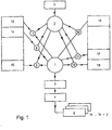
Wie in Fig. 1 veranschaulicht, werden einem Beobachtermodul 1 durch eine Vielzahl von Schlüsseln 7 bis 12 gefilterte Daten oder Signale 13 bis 18 zugeführt, die für Betriebszustände einer CNC-Werkzeugmaschine charakteristisch sind. Die Schlüssel oder Filter 7 bis 12 werden dabei durch ein Konfiguratormodul 2 so festgelegt, daß sie in zeitlichem und/oder funktionalem Zusammenhang mit den für den Betrieb der Maschine fehlerrelevanten Ereignissen und Störungen stehen. Das Beobachtermodul 1 führt die mit den Schlüsseln verknüpften Daten einem Speichermodul 3 zu. Das Speichermodul 3 kann zur Auswertung der Daten mit einem Auswertungsmodul 4 abgefragt werden. Das Konfiguratormodul 2 wird durch eine Konfigurationsdatei 5 gespeist, in dem Überwachungskriterien enthalten sind, so daß das Konfiguratormodul 2 die Schlüssel 7 bis 12 so festlegen kann, daß aufzuzeichnende Signale oder Daten aus dem Betrieb der CNC-Werkzeugmaschine in Abhängigkeit von ihrer Art, ihrem Inhalt, ihrem funktionalen oder zeitlichen Bezug zu anderen Ereignissen bestimmt werden. Zusätzlich können Kennkarten 6 erstellt werden, in denen Datensätze aufgezeichnet werden. Dies ermöglicht neben der Qualitätssicherung auch Langzeitdiagnosen durch eine regelmäßige Wiederholung der Anfertigung von Kennkarten mit anschließendem Vergleich. Damit können Kriterien für ein Frühwarnsystem für eine vorbeugende oder ereignisgesteuerte Wartungsplanung gefunden werden.As illustrated in FIG. 1, data or signals 13 to 18 which are filtered by a plurality of
Das Konfiguratormodul 2 legt die Schlüssel anhand von Boole'schen Logikregeln (UND, ODER, NICHT, etc.) fest. Alternativ dazu können auch Fuzzy-Logikregeln implementiert werden. Die Schlüssel 7 bis 12 in Fig. 1 werden jeweils auf einen analogen oder digitalen Betriebszustand der Maschine angewendet bevor sie dem Beobachtermodul 1 zugeführt werden. Da die Schlüssel oder Filter 7 bis 12 jedoch auch in Abhängigkeit voneinander festgelegt werden können, ist es möglich auch Ereignisse mit komplexen Voraussetzungen zu erfassen und dem Beobachtermodul 1 zuzuführen. In dem Beobachtermodul 1 wird die Datenform und die zeitliche Zuordnung der gefilterten Daten oder Signale für die Speicherung in dem Speichermodul 3 organisiert. Bei der Abspeicherung der Daten wird jeweils ein Zeitwert (Time stamp) mit abgelegt, so daß eine Analyse zu einer späteren Zeit im Vergleich zu anderen Daten (und deren Zeitwert) möglich ist.The
Die einzelnen Betriebszustände (Ein-/Ausgänge, Inhalte von Speicherzellen, Daten, Befehle, etc.) der CNC-Werkzeugmaschine werden durch die erfindungsgemäße Diagnoseeinrichtung in einem vorbestimmten Zeitraster (z.B. von wenigen Millisekunden) erfaßt, gefiltert und ggf. zusammen mit einer Zeitmarke gespeichert. Damit können auch Daten aus unterschiedlichen Prioritätsebenen einander zugeordnet und zeitlich korreliert ausgewertet werden. Im gleichen Zeitraster können auch alle analogen Vorgänge (Strom, Drehzahl, Temperatur, Kräfte, etc.) erfaßt, gefiltert und den entsprechenden digitalen Daten zeitlich zugeordnet und gespeichert werden. Das Speichermodul 3 ist als FIFO-Speicher organisiert, so daß zeitlich am längsten zurückliegende Daten gelöscht werden.The individual operating states (inputs / outputs, contents of memory cells, data, commands, etc.) of the CNC machine tool are recorded, filtered and possibly stored together with a time stamp by the diagnostic device according to the invention in a predetermined time grid (for example, of a few milliseconds) . This means that data from different priority levels can also be assigned to one another and evaluated in a time-correlated manner. In the same time frame, all analog processes (current, speed, temperature, forces, etc.) can also be recorded, filtered, and assigned to the corresponding digital data and saved in time. The
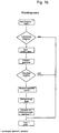
Die erfindungsgemäße Diagnoseeinrichtung ist in der Steuerung der CNC-Werkzeugmaschine dadurch implementiert, daß die einzelnen Funktionen in jeder Task der Steuerungssoftware vorhanden ist oder während der Abarbeitung jeder Task aufgerufen werden können. Wie in Fig. 1a veranschaulicht, wird dazu z.B. an jede Task des üblichen Steuerungsprogramms ein eigenes Diagnosemodul angefügt, das für die Datenaufnahme, Datenselektion und Abspeicherung mit der Zeitmarke sorgt. Da jede einzelne Task des Steuerungsprogrammes über diese Funktion verfügt, kann die Datenerfassung in Echtzeit erfolgen. Der Programmablaufplan des jeweiligen Diagnosemodells ist in Fig. 1c veranschaulicht.The diagnostic device according to the invention is implemented in the control of the CNC machine tool in that the individual functions are present in each task of the control software or can be called up during the processing of each task. As illustrated in FIG. 1 a, for this purpose, for example, a separate diagnostic module is added to each task of the usual control program, which ensures data acquisition, data selection and storage with the time stamp. Since each individual task of the control program has this function, data acquisition can be carried out done in real time. The program flow chart of the respective diagnostic model is illustrated in Fig. 1c.
Nachdem die jeweilige Task n als solche abgearbeitet ist, wird das zugehörige Diagnosemodul aufgerufen. Zunächst werden aus der Konfigurationsdatei 5 die Überwachungskriterien ausgelesen und daraus die Schlüssel generiert. Anschließend werden die in der jeweiligen Task angefallenen Daten mit den erzeugten Schlüsseln verknüpft und festgestellt, ob relevante Daten aufzuzeichnen sind. Das Beobachtermodul versieht die aufzuzeichnenden Daten mit der aktuellen Zeitmarke und speichert diese Daten zusammen mit der Zeitmarke ab.After the respective task n has been processed as such, the associated diagnostic module is called. First, the monitoring criteria are read out of the
Es versteht sich, daß das Diagnosemodul auch während der Abarbeitung einer Task (mehrfach) aufgerufen und abgearbeitet werden kann. Dies kann entweder interruptgesteuert oder durch programmgesteuerte Anrufe des Diagnosemoduls im Verlauf der jeweiligen Task erfolgen. Der Zeitabstand zwischen zwei Aufrufen des Diagnosemoduls jeder Task ist dabei so kurz, daß sichergestellt wird, alle relevanten Ereignisse in dem Prozeß zu erfassen. Außerdem kann die Generierung der Schlüssel auch im Rahmen einer Initialisierung erfolgen, so daß dies nicht während des Programmablaufs (in Echtzeit) zu erfolgen hat.It goes without saying that the diagnostic module can also be called up and processed (several times) while a task is being processed. This can either be interrupt-controlled or by program-controlled calls to the diagnostic module in the course of the respective task. The time interval between two calls to the diagnostics module of each task is so short that it is ensured that all relevant events in the process are recorded. In addition, the keys can also be generated as part of an initialization, so that this does not have to take place during the program run (in real time).
In Fig. 2 ist als einfaches Beispiel die Diagnose von sporadischen Drehzahleinbrüchen der C-Achse einer CNC-Werkzeugmaschine erläutert.In Fig. 2, the diagnosis of sporadic speed drops in the C axis of a CNC machine tool is explained as a simple example.
In der Konfigurationsdatei 5 wird festgelegt, in welchem Bereich des NC-Programms das Beobachtermodul 1 aktiv sein soll. Außerdem wird das Zeitraster der Datenerfassung (und damit auch die Aufzeichnungsgeschwindigkeit) festgelegt. Des weiteren müssen die Kriterien festgelegt werden, die eintreffen müssen, damit die Aufzeichnung gestartet wird. Als Beispiels soll die Drehzahl der C-Achse überwacht werden und bei einem Abweichen der Drehzahl um einen Toleranzwert (&& Limit) unter eine bestimmte Grenze (100 Umdrehungen/min) aufgezeichnet werden. Des weiteren enthält die Konfigurationsdatei 5 Informationen, die das Konfiguratormodul 2 in die Lage versetzen, Schlüssel oder Filter zu erzeugen, um aus der Gesamtheit der in der CNC-Werkzeugmaschine und ihrer Steuerung anfallenden Daten die für den vorliegenden Anwendungsfall notwendigen und hinreichenden Daten aus den Funktionsmodulen und deren zeitlichem Bezug zu sichern und zu extrahieren: Stromaufnahme der C-Achse, Drehzahl der C-Achse, Temperatur der C-Achse sowie digitale Steuersignale für die C-Achse.The
Dem entsprechend wird die Konfigurationsdatei ein Programm mit folgender Funktion enthalten:
Diese Programmfunktion wird aktiv, sobald in dem NC-Programm der Maschine der Befehl G0 C0 (Start C-Achse) erreicht wird. Das Zeitintervall zwischen zwei Abfragen wird durch die Zeit TI festgelegt.This program function becomes active as soon as command G0 C0 (start C-axis) is reached in the NC program of the machine. The time interval between two queries is determined by the time TI.
Fig. 3 zeigt ein Menue - SETUP "AUSWAHL". Das Menue bietet eine Einstellhilfe für die Diagnose unterschiedlicher Maschinenfunktionen. Dabei werden Triggervorbelegungen für das Menue SETUP "SPEICHERN" (siehe Fig. 6) von einem internen Speicher der elektronischen Steuerung der CNC-Werkzeugmaschine geladen. Entsprechende Referenzkurven sind in einem Speicher verfügbar.Fig. 3 shows a menu SETUP "SELECTION". The menu offers a setting aid for the diagnosis of different machine functions. Trigger pre-assignments for the SETUP "SAVE" menu (see FIG. 6) are loaded from an internal memory of the electronic control of the CNC machine tool. Corresponding reference curves are available in a memory.
Im vorliegenden Beispiel dient die Diagnose #1 dazu, die Aktivierung des Revolvers 1 zu überwachen. Alle Einstellungen zur Diagnose der Revolverfunktion werden im Menue SETUP "SPEICHERN" geladen. Die entsprechenden Referenzkurven aus vorher gemesse nen korrekten Revolverfunktionen werden in einen zweiten Speicher geladen.
- → Softkey "
Speicher 1" anwählen. - → Die Hinweismeldung "H...Diagnose
speichern 1" erscheint. - → Den Revolver im F0 Bild schalten.
- → Softkey "
Anzeigen 1" anwählen, um die aufgezeichneten digitalen Signale anzuzeigen.
Die aufgezeichneten Signale können mit denReferenzsignalen im Speicher 2 direkt vergleichen werden.
- → Select the "
Memory 1" softkey. - → The message "H ... Save
diagnosis 1" appears. - → Switch the revolver in the F0 picture.
- → Select the "
Display 1" softkey to display the recorded digital signals.
The recorded signals can be compared directly with the reference signals in thememory 2.
Die SETUP Daten werden anschließend unter einem bestimmten Dateinamen (z.B. Test 1) abgespeichert.The SETUP data is then saved under a specific file name (e.g. test 1).
Fig. 4 zeigt in schematischer Weise wie erfaßte und zusammen mit der jeweiligen Zeitmarke abgespeicherte Daten zu einem späteren Zeitpunkt dargestellt werden. Dazu werden die einzelnen Daten ab dem Triggerzeitpunkt (T1, T2, T3) dargestellt. Beispielsweise können die Daten 1 der Verlauf des Digitalsignals MY2E, die Daten 2 der Drehzahlverlauf des Motors der C-Achse und die Daten 3 ein weiteres, erst ab einem späteren Zeitpunkt erfaßtes Signal sein. Dabei werden die Daten eines Signalverlaufs entsprechend ihrer jeweiligen Zeitmarke längs der Zeitachse dargestellt und damit die einzelnen Signalverläufe zueinander korreliert.FIG. 4 shows in a schematic manner how data acquired and stored together with the respective time stamp are displayed at a later point in time. For this purpose, the individual data from the trigger time (T1, T2, T3) are displayed. For example, the
Fig. 5 zeigt eine Bildschirmdarstellung der Wiedergabe der Daten, die gemäß dem Diagnosebeispiel aus Fig. 2 erfaßt worden sind. Neben den Graphen, die die Drehzahl des Motors der C-Achse (DC) der CNC-Werkzeugmaschine wiedergibt, sowie des Graphen, der den durch den Motor fließenden Strom (SC) wiedergibt, sind auch digitale Signalverläufe (MY2E, MY2F) veranschaulicht.FIG. 5 shows a screen representation of the reproduction of the data which have been acquired in accordance with the diagnostic example from FIG. 2. In addition to the graphs that show the speed of the motor of the C-axis (DC) of the CNC machine tool and the graph that shows the current flowing through the motor (SC), digital signal profiles (MY2E, MY2F) are also illustrated.
Da die einzelnen Werte der jeweiligen Graphen zusammen mit entsprechenden Zeitmarkierungen gespeichert sind, besteht auch die Möglichkeit, andere, derzeit nicht dargestellte Signalverläufe in zeitlicher Relation zu einem oder mehreren der veranschaulichten Signalverläufe zu setzen und darzustellen, ohne daß eine neue Messung oder Diagnoseaufnahme gemacht werden muß.Since the individual values of the respective graphs are stored together with corresponding time markings, it is also possible to set and display other signal profiles, not currently shown, in relation to one or more of the signal profiles illustrated, without having to make a new measurement or diagnosis .
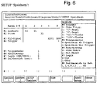
Fig. 6 zeigt ein Menue - SETUP "SPEICHERN". In den Parametern können verschiedene Daten ausgewählt werden.6 shows a menu SETUP "SAVE". Various data can be selected in the parameters.
Für folgende Achsen und Spindeln ist die Aufzeichnung der Drehzahl möglich: X1, X2, Z1, Z2, Z3, V1, Y1, S1, S2, S3, S4.The speed can be recorded for the following axes and spindles: X1, X2, Z1, Z2, Z3, V1, Y1, S1, S2, S3, S4.
Für folgende Achsen und Spindeln ist die Aufzeichnung des Stromes möglich: X1, X2, Z1, Z2, Z3, V1, Y1, S1, S2, S3, S4.The current can be recorded for the following axes and spindles: X1, X2, Z1, Z2, Z3, V1, Y1, S1, S2, S3, S4.
Für folgende "digitale Signale" ist eine Aufzeichnung möglich:
- Merker:
- M0 - M5119 (Dez)
G0 - G3071 (Dez) - Eingänge:
- X0 - X4FF (Hex)
- Ausgänge:
- Y0 - Y57F (Hex)
- NC-PLC:
- U0 - U17F (Hex)
I0 - I4BF (Hex)
S0 - S1FF (Hex)
W0 - W1FF (Hex)
J0 - J63F (Hex)
L0 - L255 (Hex)
R0 - R5899 (Dez) (nur für 1oder 0 Signale verwendbar)
- Flag:
- M0 - M5119 (Dec)
G0 - G3071 (Dec) - Inputs:
- X0 - X4FF (hex)
- Outputs:
- Y0 - Y57F (hex)
- NC-PLC:
- U0 - U17F (Hex)
I0 - I4BF (Hex)
S0 - S1FF (hex)
W0 - W1FF (hex)
J0 - J63F (Hex)
L0 - L255 (hex)
R0 - R5899 (dec) (can only be used for 1 or 0 signals)
Für jedes digitale Signal ist eine Triggerbedingung einstellbar.
- 0:
- (oder '') Start der Aufzeichnung, ohne Triggerbedingung.
- 1:
- Start der Aufzeichnung
wenn digitales Signal 1 ist. - 2:
- Start der Aufzeichnung
wenn digitales Signal 0 ist. - 3:
- Start der Aufzeichnung
wenn digitales Signal 0/1 Flanke ist. - 4:
- Start der Aufzeichnung
wenn digitales Signal 1/0 Flanke ist.
- 0:
- (or '') Start recording, without trigger condition.
- 1:
- Start recording when digital signal is 1.
- 2:
- Start recording when digital signal is 0.
- 3:
- Start of recording when digital signal is 0/1 edge.
- 4:
- Start of recording when digital signal is 1/0 edge.
Bei mehreren eingestellten Triggerbedingungen können diese durch logisch "UND" oder "ODER" verknüpft werden. Ist die Triggerbedingung erfüllt, so werden alle in #1 bis #3 eingestellten Daten aufgezeichnet.If several trigger conditions are set, these can be linked by a logical "AND" or "OR". If the trigger condition is fulfilled, all data set in # 1 to # 3 are recorded.
- 0:0:
- Speichern ab TriggerbedingungSave from trigger condition
- 1:1:
- Speichern bis zur TriggerbedingungSave until the trigger condition
- 0:0:
- ohne Makrowithout macro
- 1:1:
- mit Makrowith macro
Mit Makro bedeutet die Aktivierung der Diagnose über das Makro G309 und somit die Synchronisationsmöglichkeit zum NC-Programm. Die Aufzeichnung startet aber erst ab dem G309 Makro und wenn die Triggerbedingungen von #4 erfüllt sind.A macro means that the diagnosis is activated via the macro G309 and thus the possibility of synchronization with the NC program. However, the recording only starts from the G309 macro and when the trigger conditions of # 4 are fulfilled.
- 0:0:
- logische Verknüpfung "UND"logical link "AND"
- 1:1:
- logische Verknüpfung "ODER"logical link "OR"
Sind unter #4 Trigger mehr als eine Triggerbedingung gesetzt, so können diese Bedingungen als Und/Oder-Verknüpfung aktiviert werden.If more than one trigger condition is set under # 4 trigger, these conditions can be activated as an AND / OR link.
Für die Aufzeichnung können folgende Zeitbereiche oder Zeitabstände (Eingabe in Sekunden) angewählt werden:
1s, 3s, 6s, 9s, 12s, ... 60s.The following time ranges or time intervals (input in seconds) can be selected for recording:
1s, 3s, 6s, 9s, 12s, ... 60s.
Claims (17)
einer Rechnereinheit (1, 2, 4), einer Speichereinheit (3), einer Eingabeeinheit, und einer Ausgabeeinheit, wobei die Eingabeeinheit mit Aufnehmern verbunden ist, die analoge und/oder digitale Betriebszustände der Maschine erfassen, in diesen entsprechende Signale umsetzen und der Rechnereinheit zuführen, die Recheneinheit ihr zugefügte Signale mit vorgegebenen Schlüsseln (7 - 12) verknüpft und die Verknüpfungsergebnisse der Speichereinheit (3) und/oder der Ausgabeeinheit (4) zuführt, und wobei
die Betriebszustände in Zeitabständen erfaßbar sind, durch die sichergestellt ist, daß für den Betrieb der Maschine relevante Ereignisse und/oder Störungen in entsprechende Signale umgesetzt und der Rechnereinheit zugeführt werden.Diagnostic device for at least one electronically controlled machine, in particular a CNC machine tool, a flexible manufacturing cell, etc. with
a computer unit (1, 2, 4), a storage unit (3), an input unit, and an output unit, the input unit being connected to transducers that detect analog and / or digital operating states of the machine, convert corresponding signals into these and the computer unit lead, the arithmetic unit links the signals added to it with predetermined keys (7 - 12) and feeds the linking results to the storage unit (3) and / or the output unit (4), and wherein
the operating states can be recorded at intervals which ensure that events and / or faults relevant to the operation of the machine are converted into corresponding signals and fed to the computer unit.
Applications Claiming Priority (2)
| Application Number | Priority Date | Filing Date | Title |
|---|---|---|---|
| DE19617620 | 1996-05-02 | ||
| DE19617620A DE19617620A1 (en) | 1996-05-02 | 1996-05-02 | Diagnostic device |
Publications (2)
| Publication Number | Publication Date |
|---|---|
| EP0805382A1 true EP0805382A1 (en) | 1997-11-05 |
| EP0805382B1 EP0805382B1 (en) | 1999-10-27 |
Family
ID=7793122
Family Applications (1)
| Application Number | Title | Priority Date | Filing Date |
|---|---|---|---|
| EP97107317A Expired - Lifetime EP0805382B1 (en) | 1996-05-02 | 1997-05-02 | Diagnostic apparatus for an electronically controlled machine in which detected operating conditions are combined according to keys |
Country Status (3)
| Country | Link |
|---|---|
| EP (1) | EP0805382B1 (en) |
| AT (1) | ATE186129T1 (en) |
| DE (2) | DE19617620A1 (en) |
Cited By (5)
| Publication number | Priority date | Publication date | Assignee | Title |
|---|---|---|---|---|
| WO1999044106A1 (en) * | 1998-02-27 | 1999-09-02 | MTU MOTOREN- UND TURBINEN-UNION MüNCHEN GMBH | System and method for diagnosing the conditions of a powerplant |
| DE102005025673A1 (en) * | 2005-06-03 | 2006-12-14 | Siemens Ag | Operating method for an evaluation device for a production machine |
| DE19937515B4 (en) * | 1999-08-09 | 2008-12-24 | Abb Ag | Method and arrangement for the selective recording of messages |
| US9310795B2 (en) | 2008-11-25 | 2016-04-12 | Pilz Gmbh & Co. Kg | Safety controller and method for controlling an automated installation |
| CN113614654A (en) * | 2019-03-19 | 2021-11-05 | 西门子股份公司 | Safety-relevant diagnostic messages |
Families Citing this family (4)
| Publication number | Priority date | Publication date | Assignee | Title |
|---|---|---|---|---|
| US6515665B1 (en) * | 1999-06-21 | 2003-02-04 | Tektronix, Inc. | Data filtering/suppression of data acquisitions/samples for multi-channel electronic display and analysis |
| JP3834307B2 (en) | 2003-09-29 | 2006-10-18 | ファナック株式会社 | Robot system |
| DE102010002183B4 (en) | 2010-02-22 | 2013-01-10 | Koenig & Bauer Aktiengesellschaft | Method for carrying out in a printing machine with at least one machine unit and with multiple drives |
| DE102022120738A1 (en) | 2022-08-17 | 2024-02-22 | TRUMPF Werkzeugmaschinen SE + Co. KG | Method and system for determining an operating state of a machine tool |
Citations (2)
| Publication number | Priority date | Publication date | Assignee | Title |
|---|---|---|---|---|
| US3795916A (en) * | 1969-11-14 | 1974-03-05 | Westinghouse Electric Corp | Process operation error monitor and error message system |
| EP0418787A2 (en) * | 1989-09-19 | 1991-03-27 | Siemens Aktiengesellschaft | Method for controlling the operation of a machine tool |
Family Cites Families (4)
| Publication number | Priority date | Publication date | Assignee | Title |
|---|---|---|---|---|
| GB2104685B (en) * | 1981-08-24 | 1985-12-18 | Omron Tateisi Electronics Co | Programmable controller |
| JPS59154321A (en) * | 1983-02-22 | 1984-09-03 | Toshiba Mach Co Ltd | Display device for monitoring data |
| JPH0670764B2 (en) * | 1985-03-06 | 1994-09-07 | 株式会社日立製作所 | Sequence control device |
| DE4408603A1 (en) * | 1994-03-08 | 1995-09-14 | Mannesmann Ag | Increase of security of hierarchically structured automation systems |
-
1996
- 1996-05-02 DE DE19617620A patent/DE19617620A1/en not_active Withdrawn
-
1997
- 1997-05-02 AT AT97107317T patent/ATE186129T1/en not_active IP Right Cessation
- 1997-05-02 DE DE59700609T patent/DE59700609D1/en not_active Expired - Lifetime
- 1997-05-02 EP EP97107317A patent/EP0805382B1/en not_active Expired - Lifetime
Patent Citations (2)
| Publication number | Priority date | Publication date | Assignee | Title |
|---|---|---|---|---|
| US3795916A (en) * | 1969-11-14 | 1974-03-05 | Westinghouse Electric Corp | Process operation error monitor and error message system |
| EP0418787A2 (en) * | 1989-09-19 | 1991-03-27 | Siemens Aktiengesellschaft | Method for controlling the operation of a machine tool |
Cited By (7)
| Publication number | Priority date | Publication date | Assignee | Title |
|---|---|---|---|---|
| WO1999044106A1 (en) * | 1998-02-27 | 1999-09-02 | MTU MOTOREN- UND TURBINEN-UNION MüNCHEN GMBH | System and method for diagnosing the conditions of a powerplant |
| DE19808197C2 (en) * | 1998-02-27 | 2001-08-09 | Mtu Aero Engines Gmbh | System and method for diagnosing engine conditions |
| US6574613B1 (en) | 1998-02-27 | 2003-06-03 | Jorge Moreno-Barragan | System and method for diagnosing jet engine conditions |
| DE19937515B4 (en) * | 1999-08-09 | 2008-12-24 | Abb Ag | Method and arrangement for the selective recording of messages |
| DE102005025673A1 (en) * | 2005-06-03 | 2006-12-14 | Siemens Ag | Operating method for an evaluation device for a production machine |
| US9310795B2 (en) | 2008-11-25 | 2016-04-12 | Pilz Gmbh & Co. Kg | Safety controller and method for controlling an automated installation |
| CN113614654A (en) * | 2019-03-19 | 2021-11-05 | 西门子股份公司 | Safety-relevant diagnostic messages |
Also Published As
| Publication number | Publication date |
|---|---|
| EP0805382B1 (en) | 1999-10-27 |
| DE19617620A1 (en) | 1997-11-13 |
| DE59700609D1 (en) | 1999-12-02 |
| ATE186129T1 (en) | 1999-11-15 |
Similar Documents
| Publication | Publication Date | Title |
|---|---|---|
| EP2419799A1 (en) | Method for processing process state data and/or machine state data of a machine tool | |
| WO2008064763A1 (en) | Error logging method for a coating plant | |
| EP2356527B1 (en) | Safety control and method for controlling an automated system having a plurality of system hardware components | |
| EP0789864B1 (en) | Monitoring system for an industrial plant | |
| EP1296207B1 (en) | HMI apparatus and method for operating a technical installation, automation system with HMI apparatus and computer program product with program for carrying out the method in a HMI apparatus or in an automation system | |
| EP1738185B1 (en) | Signal processing device with synchronous triggering | |
| DE4406723B4 (en) | Method for monitoring the operating state of a machine or plant | |
| EP0805382B1 (en) | Diagnostic apparatus for an electronically controlled machine in which detected operating conditions are combined according to keys | |
| DE102005041632A1 (en) | Method and device for monitoring a technical device | |
| EP2419798A1 (en) | Method for providing information about the wear and tear of a component of a machine and method for providing a replacement algorithm | |
| DE2729372C3 (en) | Arrangement for monitoring a computer-guided, numerically controlled machine tool | |
| EP1117023B1 (en) | Device for fault diagnosis during motor vehicle operation | |
| EP1269358A1 (en) | Method and system for recording and saving data from a production plant | |
| DE3606518A1 (en) | METHOD FOR DETECTING AND REPORTING ERRORS AND CAUSES FOR FAULTS IN THE PROCESS OF PROCESSES CONTROLLED OR CONTROLLED BY AUTOMATION MEANS | |
| EP1079289A2 (en) | Projection unit for corresponding blocks of diagnose data of a system with a control unit and command- and/or monitoring-unit and system with means for comparison of versions of blocks of diagnose data | |
| DE3413330A1 (en) | Method for monitoring and localising a fault in the fabrication cycles of an automatic production line and a device for carrying it out | |
| DE19815647A1 (en) | Method for synchronizing a local to a central time base, and device for carrying out the method with preferred uses | |
| DE10115897C2 (en) | Method and device for providing information for the analysis of faults in a technical installation | |
| EP3598250B1 (en) | Sensor assembly | |
| DE102022134209B3 (en) | Method, diagnostic device and system for monitoring operation of an internal combustion engine | |
| WO2009000422A2 (en) | Method and device for monitoring an automated system | |
| EP4246261A1 (en) | Control system for a technical plant and method of operation | |
| DE19805518B4 (en) | Method and device for analyzing protection signals for a number of safety-relevant plant parts of a technical installation | |
| DE102007027262A1 (en) | Action modules for condition-based maintenance | |
| DE102018105872A1 (en) | Method for analyzing a communication quality |
Legal Events
| Date | Code | Title | Description |
|---|---|---|---|
| PUAI | Public reference made under article 153(3) epc to a published international application that has entered the european phase |
Free format text: ORIGINAL CODE: 0009012 |
|
| AK | Designated contracting states |
Kind code of ref document: A1 Designated state(s): AT CH DE FR GB IT LI SE |
|
| 17P | Request for examination filed |
Effective date: 19971121 |
|
| 17Q | First examination report despatched |
Effective date: 19980127 |
|
| GRAG | Despatch of communication of intention to grant |
Free format text: ORIGINAL CODE: EPIDOS AGRA |
|
| GRAG | Despatch of communication of intention to grant |
Free format text: ORIGINAL CODE: EPIDOS AGRA |
|
| GRAG | Despatch of communication of intention to grant |
Free format text: ORIGINAL CODE: EPIDOS AGRA |
|
| GRAH | Despatch of communication of intention to grant a patent |
Free format text: ORIGINAL CODE: EPIDOS IGRA |
|
| GRAH | Despatch of communication of intention to grant a patent |
Free format text: ORIGINAL CODE: EPIDOS IGRA |
|
| GRAA | (expected) grant |
Free format text: ORIGINAL CODE: 0009210 |
|
| ITF | It: translation for a ep patent filed | ||
| AK | Designated contracting states |
Kind code of ref document: B1 Designated state(s): AT CH DE FR GB IT LI SE |
|
| REF | Corresponds to: |
Ref document number: 186129 Country of ref document: AT Date of ref document: 19991115 Kind code of ref document: T |
|
| REG | Reference to a national code |
Ref country code: CH Ref legal event code: EP |
|
| GBT | Gb: translation of ep patent filed (gb section 77(6)(a)/1977) |
Effective date: 19991028 |
|
| REF | Corresponds to: |
Ref document number: 59700609 Country of ref document: DE Date of ref document: 19991202 |
|
| ET | Fr: translation filed | ||
| PLBE | No opposition filed within time limit |
Free format text: ORIGINAL CODE: 0009261 |
|
| STAA | Information on the status of an ep patent application or granted ep patent |
Free format text: STATUS: NO OPPOSITION FILED WITHIN TIME LIMIT |
|
| 26N | No opposition filed | ||
| REG | Reference to a national code |
Ref country code: GB Ref legal event code: IF02 |
|
| PGFP | Annual fee paid to national office [announced via postgrant information from national office to epo] |
Ref country code: SE Payment date: 20070522 Year of fee payment: 11 Ref country code: AT Payment date: 20070522 Year of fee payment: 11 |
|
| PGFP | Annual fee paid to national office [announced via postgrant information from national office to epo] |
Ref country code: GB Payment date: 20080515 Year of fee payment: 12 |
|
| PG25 | Lapsed in a contracting state [announced via postgrant information from national office to epo] |
Ref country code: AT Free format text: LAPSE BECAUSE OF NON-PAYMENT OF DUE FEES Effective date: 20080502 |
|
| GBPC | Gb: european patent ceased through non-payment of renewal fee |
Effective date: 20090502 |
|
| PG25 | Lapsed in a contracting state [announced via postgrant information from national office to epo] |
Ref country code: GB Free format text: LAPSE BECAUSE OF NON-PAYMENT OF DUE FEES Effective date: 20090502 |
|
| PG25 | Lapsed in a contracting state [announced via postgrant information from national office to epo] |
Ref country code: SE Free format text: LAPSE BECAUSE OF NON-PAYMENT OF DUE FEES Effective date: 20080503 |
|
| PGFP | Annual fee paid to national office [announced via postgrant information from national office to epo] |
Ref country code: CH Payment date: 20140519 Year of fee payment: 18 Ref country code: IT Payment date: 20140520 Year of fee payment: 18 Ref country code: DE Payment date: 20140528 Year of fee payment: 18 |
|
| PGFP | Annual fee paid to national office [announced via postgrant information from national office to epo] |
Ref country code: FR Payment date: 20140528 Year of fee payment: 18 |
|
| REG | Reference to a national code |
Ref country code: DE Ref legal event code: R119 Ref document number: 59700609 Country of ref document: DE |
|
| REG | Reference to a national code |
Ref country code: CH Ref legal event code: PL |
|
| PG25 | Lapsed in a contracting state [announced via postgrant information from national office to epo] |
Ref country code: LI Free format text: LAPSE BECAUSE OF NON-PAYMENT OF DUE FEES Effective date: 20150531 Ref country code: CH Free format text: LAPSE BECAUSE OF NON-PAYMENT OF DUE FEES Effective date: 20150531 Ref country code: IT Free format text: LAPSE BECAUSE OF NON-PAYMENT OF DUE FEES Effective date: 20150502 |
|
| REG | Reference to a national code |
Ref country code: FR Ref legal event code: ST Effective date: 20160129 |
|
| PG25 | Lapsed in a contracting state [announced via postgrant information from national office to epo] |
Ref country code: DE Free format text: LAPSE BECAUSE OF NON-PAYMENT OF DUE FEES Effective date: 20151201 |
|
| PG25 | Lapsed in a contracting state [announced via postgrant information from national office to epo] |
Ref country code: FR Free format text: LAPSE BECAUSE OF NON-PAYMENT OF DUE FEES Effective date: 20150601 |