EP0805235B1 - Railway sleepers of ladder-like shape - Google Patents
Railway sleepers of ladder-like shape Download PDFInfo
- Publication number
- EP0805235B1 EP0805235B1 EP97107211A EP97107211A EP0805235B1 EP 0805235 B1 EP0805235 B1 EP 0805235B1 EP 97107211 A EP97107211 A EP 97107211A EP 97107211 A EP97107211 A EP 97107211A EP 0805235 B1 EP0805235 B1 EP 0805235B1
- Authority
- EP
- European Patent Office
- Prior art keywords
- sleepers
- connectors
- concrete
- coating
- portions
- Prior art date
- Legal status (The legal status is an assumption and is not a legal conclusion. Google has not performed a legal analysis and makes no representation as to the accuracy of the status listed.)
- Expired - Lifetime
Links
Images


Classifications
-
- E—FIXED CONSTRUCTIONS
- E01—CONSTRUCTION OF ROADS, RAILWAYS, OR BRIDGES
- E01B—PERMANENT WAY; PERMANENT-WAY TOOLS; MACHINES FOR MAKING RAILWAYS OF ALL KINDS
- E01B3/00—Transverse or longitudinal sleepers; Other means resting directly on the ballastway for supporting rails
- E01B3/28—Transverse or longitudinal sleepers; Other means resting directly on the ballastway for supporting rails made from concrete or from natural or artificial stone
- E01B3/38—Longitudinal sleepers; Longitudinal sleepers integral or combined with tie-rods; Combined longitudinal and transverse sleepers; Layers of concrete supporting both rails
Definitions
- the present invention relates to sleepers of a mixed rigid connection structure having a ladder-like shape (hereinafter, referred to as a ladder-type sleeper for railway tracks), consisting of longitudinal beams made of concrete and connectors constructed of steel pipes as a railway track laid on a bed of a railroad.
- a ladder-type sleeper for railway tracks consisting of longitudinal beams made of concrete and connectors constructed of steel pipes as a railway track laid on a bed of a railroad.
- a railroad is an exclusive road constructed by a track and a base supporting the track.
- a railway track comprises a bed, sleepers and rails and the base comprises a road base supporting the bed and a railway structure:
- a ballast is generally used for the bed and impact force or vibration by a train are absorbed by an elasticity thereof.
- a slab track where the sleepers and the ballast are replaced by concrete and mortar is used for facilitating track maintenance.
- the sleeper There are three roles of the sleeper, that is, a sleeper function for alleviating a load applied on the bed by distributing the weight of train widely over the bed and preventing rails from causing aged sinking, a tie function of maintaining constant an interval (rail gauge) between left and right rails and a lateral resistant and longitudinal resistant function to make rails unmovable in the left and right direction and in the forward and rearward direction against the operation of a lateral pressure and a force in the direction of the axes of the rails.
- a sleeper function for alleviating a load applied on the bed by distributing the weight of train widely over the bed and preventing rails from causing aged sinking
- a tie function of maintaining constant an interval (rail gauge) between left and right rails and a lateral resistant and longitudinal resistant function to make rails unmovable in the left and right direction and in the forward and rearward direction against the operation of a lateral pressure and a force in the direction of the axes of the rails.
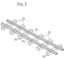
- sleepers 32 are arranged orthogonally to the axial direction of two rails 31a and 31b at predetermined intervals (for example, about 750 mm).
- a sleeper made of wood or a sleeper made of concrete is used for the sleeper 32.
- the sleepers constitute bases placed independently from each other for intermittently supporting the rails and accordingly, they support rails only partially. Therefore, every time a train passes through, portions of the rails which are not brought into contact with the sleepers are made to vibrate and a noise referred to as "rolling sound" is caused.
- the formation of the sleepers made of concrete has been progressed along with long welded rails as means for acceleration and comfortability of transportation.
- a large temperature dependent axial compression force (a force stored at the inside of rails for fixing unmovably the rails by sleepers against elongation and contraction of the rails by the change in temperature) is operated on the rails with the formation of long welded rails and therefore, rails are bent in the upper and down direction and in the left and right direction when the fixing force is weak.
- the sleepers made of concrete which are provided with a large weight and a large rail fastening force, become an important track component factor exceeding a role of a substitute for sleepers made of wood in the present age high speed railroad.
- the sleepers made of concrete constitute the important track component factor exceeding the role of the substitute for sleepers made of wood in the present age high speed railroad, the configuration thereof is quite equal to that of the sleepers made of wood whereby achievement of labor saving in maintenance of ballasted tracks is limited.
- the maintenance operation is referred to as a representative of the so called “3K operations" in Japan (dangerous, laborious and dirty operation) as a result of limiting the operational maintenance time to the middle of night in regard with the operational time of the railroad and is an operation shied away from by young people.
- a pretension type, prestressed reinforced concrete structure (hereinafter, referred to as a pretension type PRC structure) where upper and lower prestressing strands 42 are pretensioned and the tension force is released after curing a fed concrete 43, and the longitudinal beams 41 having the pretension type PRC structure are designed by a limited design method whereby a necessary and sufficient load bearing function can be ensured even with a least sectional area under conditions of a ballasted bed where a disadvantageous support state must be predicted.
- small diameter, thick wall steel pipes 44 having a rigidity necessary for holding the rail gauge are arranged at intervals of 3.0 m, embedded portions 45 of the small diameter, thick wall steel pipes 44 are inserted between the upper and lower prestressing strands 42 which constitute main axial reinforcement members of the longitudinal beams 41 and which are under tension, and a mixed rigid connection structure having a ladder-like shape is formed by integrating the connectors solidly with the longitudinal beams 41 by feeding a concrete 43 whereby the tie function is sufficiently ensured.
- numeral 46 in the drawings designates a star lap
- numeral 47 designates an embedding metal piece
- numeral 48 designates a rail
- numeral 49 designates a rail fastener.
- a carbon steel pipe for general structure STK 540 prescribed in JIS (Japanese Industrial Standards) G3444 is used in view both of rigidity and operational performance and in view of cost, and ribs 51 are fixedly welded to both end portions of the small diameter, thick wall steel pipe 44 as shown by Fig. 6.
- portions of the small diameter, thick wall steel pipe 44 exposed to the atmosphere are coated with a rubber lining 52 by a curing treatment for preventing corrosion since waterproofing, stray current resistance (insulation performance), impact resistance and weather resistance are necessary for these portions in view of environments where they are used.
- the Document EP-0 675 226 A1 describes ladder-type sleepers for railway tracks, the sleepers being formed by beams of prestressed concrete provided on the underside of each of a pair of rails in the longitudinal direction, and by multiple connectors provided to connect the longitudinal beams at intervals.
- the ends of the connectors are embedded in the beams and intersect with parallel, longitudinal pre-stressing strands which are embedded in the beams.
- the connectors are slender and may consist of steel pipes having a circular, angular or any other cross-sectional shape.
- the connectors are provided with ribs which protrude in the radial direction and transmit rotational force of the connector into the concrete. Small ribs are also provided on the upper and lower surfaces of these ribs in order to transmit the force in the transverse direction from the connector to the concrete.
- the Document US-A-3 039 695 describes a reinforced concrete railway tie consisting of a pair of substantially identical concrete blocks, each having a bearing surface for supporting one of the rails and being formed with an aperture extending at least partially transversely through each block.
- the apertures may be formed in the blocks by placing a core therein when the blocks are cast and are adapted to each receive snugly therein one of the ends of a removable tie bar consisting of a pipe flattened to elliptical or oval cross-section.
- This cross-section not only precludes rotation of the bar in the transverse aperture, but also orients the bar so that a pair of apertures in each end of the bar are uppermost and can be aligned with two vertical passages formed in each block to communicate with the transverse aperture, so that retaining members for anchoring the rails to the blocks and for securing the tie bar to the block may be passed through the vertical passages in the block and the apertures in each end of the bar.
- the Document GB-A-815 128 describes concrete sleepers for railway tracks, the sleepers consisting of two concrete bodies joined to one another and held together by at least one tensioned reinforcing rod supported by the concrete.
- the concrete bodies are joined to each other by at least one iron or steel tube surrounding the rod.
- the tube is filled with concrete or a similar mass to support the rod and to take up stresses between the concrete bodies and possible torsional and/or bending movements between the concrete bodies without permanent deformation.
- the present invention makes it possible to dispense with the installation of ribs on steel pipes having the tie function of the sleepers.
- corrosion resistance can be attained less expensively than by providing a rubber lining, whereby the requirements of a reduction in cost and achievement of mass production can be met.
- the inventors have carried out an intensive test and study in order to achieve the above-described object. As a result, they have reached the present invention by clarifying that a rotation preventive and drawing preventive function could be provided by flattening the both end portions of the connector constructed of a steel pipe in the horizontal direction without installing ribs at side faces of the both end portions of the connector constructed of a steel pipe having the tie function of the ladder-type sleeper for railway tracks, and further, the corrosion resistance could be attained less expensively than in the baking operation of a rubber lining by coating a corrosion resistant coating at portions of the connector constructed of a steel pipe exposed to the atmosphere and fitting a rubber ring on the outer periphery whereby the cost reduction and the mass production can be achieved.
- both end portions of the connector constructed of a steel pipe are flattened in the horizontal direction.
- a rotation preventive and drawing preventive function can be attained without fixedly welding ribs at side faces of the both end portions by flattening in the horizontal direction the both end portions of the connector constructed of a steel pipe in this way.
- an amount of working can be specified to a range of from a flattened amount of 1/8 of the outer diameter of the connector constructed of a steel pipe to an amout thereof whereby the inner faces are brought into close contact, depending on materials.
- the bending strength of the connector constructed of a steel pipe can be enhanced by filling concrete at the inside of the connector constructed of a steel pipe.
- a connector made of a steel pipe of a ladder-type sleeper for railway tracks where the both end portions of the connector constructed of a steel pipe are flattened in the horizontal direction and a corrosion resistant coating is coated on portions of the connector constructed of a steel pipe exposed to the atmosphere.
- a rotation preventive and drawing preventive function can be attained by flattening the both end portions of the connector without fixedly welding ribs on side faces of the both end portions.
- a corrosion resistant coating at portions of the connector constructed of a steel pipe exposed to the atmosphere corrosion resistance and stray current resistance can be achieved more inexpensively than in a rubber lining by a curing treatment.
- a polyolefin coating, an epoxy coating, a polyurethane coating, a zinc plating (a galvanized coating), an aluminum plating (an aluminum coating), a zinc-aluminum coating or a rubber coating is executed as the corrosion resistant coating. Furthermore, by fitting a rubber ring excellent in the weather resistance and the impact resistance onto the outer periphery of the corrosion resistant coating, the waterproofing, the stray current resistance, the impact resistance and the weather resistance can be achieved more inexpensively than in the rubber lining by a curing treatment.
- a steel pipe coated with a corrosion resistant coating is cut into a predetermined dimension of a connector, a rubber ring is fitted at portions of the connector constructed of a steel pipe exposed to the atmosphere and thereafter, the both end portions of the pipe are flattened in the horizontal direction.
- the flattening operation is executed by pressing.
- the flattening is executed until a thickness of the flattened portion falls in a range of 1/8 of the outer diameter to an amount whereby the inner faces are brought into close contact with each other.
- the sufficient rotation preventive and drawing preventive function cannot be achieved with the flattened thickness, the amount of which does not reach 7/8 of the outer diameter.
- the flattening is executed such that the amount of flattened thickness reaches 2/3 through 1/2 of the outer diameter in consideration of filling of concrete to the inside of the connector constructed of a steel pipe.
- the pipe in the flattening operation of the both end portions of the connector constructed of a steel pipe, the pipe is flattened in the horizontal direction because if it is flattened in the vertical direction, the insertion of the pipe between the prestressing strands which are the main reinforcement steel materials of the longitudinal beams, is hindered.
- polyethylene low through high density
- polypropylene polybutene and polystyrene
- polyethylene is excellent in view of the cost and the corrosion resistant function.
- an inexpensive inorganic synthetic pigment such as carbon black or the like may be added thereto by 0.5 through 3.0 weight % within a range where the physical property of polyethylene per se is not deteriorated.
- an asphalt synthetic group pressure sensitive adhesive and a polyethylene group adhesive agent, modified polyethylene and ethylene-vinyl acetate copolymer or the like may be interposed between the steel pipe and polyethylene as an adhesive agent.
- the connector constructed of a steel pipe is coated with, for example, the polyethylene coating as a corrosion resistant coating over the entire length of the steel pipe and thereafter, cut into a predetermined dimension of a connector, and the coated polyethylene film at the both end portions of the pipe needs to be removed before the flattening of both end portions in order to promote the adhesion strength of the both end portions of the pipe in respect of the concrete of the longitudinal beams.
- a coating system where after subjecting the steel pipe to a chromate treatment (total amount of chrome adhesion; 100 through 1000 g/m 2 ), an epoxy group primer is coated (thickness; 10 through 100 ⁇ m), modified polyethylene or an adhesive agent of ethylene-vinyl acetate copolymer is coated (thickness; 50 through 300 ⁇ m) and polyethylene is coated (thickness; 0.6 through 3.0 mm). Also a rubber coating inclusive of carbon black or the like is coated by approximately several millimeters in consideration of the corrosion resistance and the weather resistance.
- the pipe is dipped in a plating tank whereby the plating is executed before flattening the both end portions in the horizontal direction whereby the mass production can be realized without requiring time and labor.
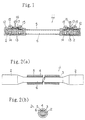
- FIG. 1 is a sectional structural view of a ladder-type sleeper for railway tracks using a connector constructed of a steel pipe as used in the present invention
- Figs. 2(a) and 2(b) illustrate the connector constructed of a steel pipe as used in the present invention where Fig. 2(a) is a plane view omitting a portion of a central portion thereof and Fig. 2(b) is a front view of the connector constructed of a steel pipe as used in the present invention.
- numeral 1 designates a connector constructed of a steel pipe constituted by a thick wall small diameter pipe 6 having flattened portions 2 constructed by flattening both end portions of the pipe such that the thickness of the flattened portion becomes 1/2 of the outer diameter height in the horizontal direction, where a polyethylene coating layer 4 is coated on the outer face of the central portion via a pressure sensitive adhesive 3 for a corrosion resistant coating, a rubber ring 5 is fitted onto the outer face of the polyethylene coating layer 4 and concrete is filled at the inside thereof.
- numeral 11 designates a ladder-type sleeper for railway tracks using the steel pipe connector 1, which is provided with a mixed rigid connection structure in a ladder-like shape integrated with the longitudinal beams 12 made of concrete and the connectors constructed of steel pipes 1 by feeding concrete.
- the ladder-type sleeper 11 for railway tracks is provided with a pretension type PRC structure where a plurality of prestressing strands 13 are arranged at the upper and lower portions of the longitudinal beams 12 made of concrete and having the sleeper function, stirrups 14 are arranged at the outer peripheries of the prestressing strands 13 at predetermined intervals, rail fasteners 15 are arranged at predetermined intervals, the flattened portions 2 at both end portions of the connector constructed of a steel pipe 1 having the tie function are inserted between the upper and lower prestressing strands 13 such that a distance between rails 16 laid on the ladder-type sleeper 11 for railway tracks becomes a predetermined distance, the longitudinal beams 12 made of concrete and the connector constructed of a steel pipe 1 are solidly integrated by pretensioning the prestressing strands 13 and feeding concrete and the tension of the prestressing strands 13 is released after curing the concrete, whereby prestress is introduced into the longitudinal beams 12 made of concrete.
- the connector constructed of a steel pipe 1 having the tie function of the ladder-type sleeper 11 for railway tracks is provided with a rigidity necessary for maintaining the rail gauge since it is constituted by the thick wall, small diameter steel pipe 6 in which concrete is filled. Further, the connector constructed of a steel pipe 1 is provided with the rotation preventive and drawing preventive function by having the flattened portions 2 in the horizontal direction at the both end portions of the pipe without especially installing ribs at side portions of the both end portions.
- the polyethylene coating layer 4 excellent in waterproof and insulating performance is provided via the pressure sensitive adhesive 3 at the central portion of the thick wall, small diameter steel pipe 6 of the connector constructed of a steel pipe 1 which is not embedded into the longitudinal beams 12 made of concrete, and the rubber ring 5 excellent in the weather resistance and the impact resistance is fitted onto the outer face thereof and therefore, the connector constructed of a steel pipe 1 is excellent in the waterproofing, the insulating performance, the weather resistance and the impact resistance under environments where it is used, whereby the corrosion resistance of the thick wall, small diameter steel pipe 6 can be guaranteed over a long period of time.
- the connector constructed of a steel pipe 1 of the ladder-type sleeper 11 for railway tracks in comparison with the conventional thick wall, small diameter steel pipe 6 where ribs are installed at the side portion of the both end portions of the pipe, and the rubber coating by a curing treatment is coated at the central portion, only the polyethylene coating layer 4 is coated at the thick wall, small diameter steel pipe 6 and the rubber ring 5 is fitted to the central portion and accordingly, the connector constructed of a steel pipe 1 is inexpensive in view of cost, provided with the sufficient tie function and the rotation preventive and drawing preventive function, as well as provided with the corrosion protection function and the impact resistance for preventing impact defects caused by a ballast or the like, whereby repair is not necessary over a long period of time.
- a connector constructed by a steel pipe for connecting longitudinal beams made of concrete and having the tie function of a ladder-type sleeper for railway tracks there was prepared a conventional example where ribs in an H-type shape having a thickness of 6 mm and a width of 30 mm made of SS 400 of a rolled steel material for general structure prescribed in JIS G3101, were fixedly welded to both side faces along 50 mm through 300 mm from both end portions of a small diameter, thick wall steel pipe having an outer diameter of 76.3 mm, a wall thickness of 9.0 mm and a length of 1476 mm made of STK 540 of a carbon steel pipe for general structure prescribed in JIS G3444.
- a rubber coating was coated at the central portion having a length of 710 mm by a curing treatment and- concrete was filled at the inside of the pipe.
- a small diameter, thick wall steel pipe having an outer diameter of 76.3 mm, a wall thickness of 9.0 mm and a length of 1476 mm made of STK 540 of a carbon steel pipe for general structure prescribed in JIS G3444, were flattened by pressing such that a thickness of the flattened portion became 1/2 of the outer diameter
- an adhesive agent of ethylene-vinyl acetate copolymer was coated at the central portion having a length of 710 mm by a thickness of 200 ⁇ m
- a polyethylene coating was executed by a thickness of 1.5 mm and a urethane rubber ring was fitted onto the outer face of the pipe.
- the invention example is comparable to the conventional example and the fabrication cost of the invention example is reduced to substantially 2/3 of that of the conventional example, whereby the cost of the ladder-type sleeper for railway tracks can be reduced by that amount.
- the connector constructed of a steel pipe of the ladder-type sleeper for railway tracks of the present invention in comparison with the conventional connector constructed of a steel pipe where ribs are fixedly welded to side faces of the both end portions of a small diameter, thick wall steel pipe, and a rubber coating by a curing treatment is coated at the central portion, only the both end portions of the small diameter, thick wall steel pipe where the polyethylene coating is coated and the rubber ring is fitted onto the outer surface, are flattened by pressing and therefore, the fabrication cost can significantly be reduced and the tie function and the rotation preventive and drawing preventive function are sufficiently provided, which can significantly contribute to reduction in the cost of the ladder-type sleeper for railway tracks.
Landscapes
- Engineering & Computer Science (AREA)
- Architecture (AREA)
- Civil Engineering (AREA)
- Structural Engineering (AREA)
- Road Paving Structures (AREA)
- Ladders (AREA)
Description
- The present invention relates to sleepers of a mixed rigid connection structure having a ladder-like shape (hereinafter, referred to as a ladder-type sleeper for railway tracks), consisting of longitudinal beams made of concrete and connectors constructed of steel pipes as a railway track laid on a bed of a railroad.
- A railroad is an exclusive road constructed by a track and a base supporting the track. A railway track comprises a bed, sleepers and rails and the base comprises a road base supporting the bed and a railway structure: A ballast is generally used for the bed and impact force or vibration by a train are absorbed by an elasticity thereof. As a railroad of a super-express train, a slab track where the sleepers and the ballast are replaced by concrete and mortar is used for facilitating track maintenance. There are three roles of the sleeper, that is, a sleeper function for alleviating a load applied on the bed by distributing the weight of train widely over the bed and preventing rails from causing aged sinking, a tie function of maintaining constant an interval (rail gauge) between left and right rails and a lateral resistant and longitudinal resistant function to make rails unmovable in the left and right direction and in the forward and rearward direction against the operation of a lateral pressure and a force in the direction of the axes of the rails.
- It is said that the total number of sleepers used in railroads in the world amounts to three billion pieces among which four hundred million pieces are sleepers made of concrete. Sleepers made of wood currently share an overwhelmingly high proportion as indicated by the Chinese ideograph for "pillow wood". However, the use of sleepers made of wood which gives rise to exhaustion of forest resources tends to be restricted year by year in view of environmental conservation, above all preservation of forest resources. Therefore, an enormous worldwide demand is estimated in future in respect of sleepers made of concrete contributing to the environmental conservation and a further expectation is put therefor. Approximately twenty million pieces per year of sleepers made of concrete are produced as a substitute for sleepers made of wood as well as sleepers for new line construction. Especially, in advanced countries of railroad such as Europe, Japan and the like, approximately a half of the yearly demand of sleepers is shared by sleepers made of concrete.
- As illustrated by Fig. 3, according to a sleeper track of a conventional railroad,
sleepers 32 are arranged orthogonally to the axial direction of two rails 31a and 31b at predetermined intervals (for example, about 750 mm). A sleeper made of wood or a sleeper made of concrete is used for thesleeper 32. According to the sleeper track, the sleepers constitute bases placed independently from each other for intermittently supporting the rails and accordingly, they support rails only partially. Therefore, every time a train passes through, portions of the rails which are not brought into contact with the sleepers are made to vibrate and a noise referred to as "rolling sound" is caused. Further, in respect of a track where a ballast is laid on a bed, warp of the rails is liable to be caused by repeated application of the weight of the train, which gives rise to rocking of a running train. An increase in the rocking of a running train deteriorates acceleratingly the track state. - Meanwhile, the formation of the sleepers made of concrete has been progressed along with long welded rails as means for acceleration and comfortability of transportation. A large temperature dependent axial compression force (a force stored at the inside of rails for fixing unmovably the rails by sleepers against elongation and contraction of the rails by the change in temperature) is operated on the rails with the formation of long welded rails and therefore, rails are bent in the upper and down direction and in the left and right direction when the fixing force is weak. In order to prevent the deformation of the rails, the sleepers made of concrete which are provided with a large weight and a large rail fastening force, become an important track component factor exceeding a role of a substitute for sleepers made of wood in the present age high speed railroad.
- Although as described above, the sleepers made of concrete constitute the important track component factor exceeding the role of the substitute for sleepers made of wood in the present age high speed railroad, the configuration thereof is quite equal to that of the sleepers made of wood whereby achievement of labor saving in maintenance of ballasted tracks is limited. Especially, enormous cost and labor are necessary in the maintenance of ballasted tracks, however, the maintenance operation is referred to as a representative of the so called "3K operations" in Japan (dangerous, laborious and dirty operation) as a result of limiting the operational maintenance time to the middle of night in regard with the operational time of the railroad and is an operation shied away from by young people.
- Recently, a ladder-type sleeper is suggested in "RRR", 1995. 12, p8-28 issued by a foundation of the Railway Technical Research Institute in order to reduce the maintenance operation of the ballasted track. Specific structure and feature of the ladder-type sleepers for railway tracks will be explained in reference to Fig. 4 and Fig. 5. In respect of
longitudinal beams 41 having the sleeper function, there is adopted a pretension type, prestressed reinforced concrete structure (hereinafter, referred to as a pretension type PRC structure) where upper andlower prestressing strands 42 are pretensioned and the tension force is released after curing afed concrete 43, and thelongitudinal beams 41 having the pretension type PRC structure are designed by a limited design method whereby a necessary and sufficient load bearing function can be ensured even with a least sectional area under conditions of a ballasted bed where a disadvantageous support state must be predicted. With respect to connectors bearing the tie function, small diameter, thickwall steel pipes 44 having a rigidity necessary for holding the rail gauge, are arranged at intervals of 3.0 m, embeddedportions 45 of the small diameter, thickwall steel pipes 44 are inserted between the upper and lowerprestressing strands 42 which constitute main axial reinforcement members of thelongitudinal beams 41 and which are under tension, and a mixed rigid connection structure having a ladder-like shape is formed by integrating the connectors solidly with thelongitudinal beams 41 by feeding aconcrete 43 whereby the tie function is sufficiently ensured. Incidentally,numeral 46 in the drawings designates a star lap,numeral 47 designates an embedding metal piece,numeral 48 designates a rail andnumeral 49 designates a rail fastener. - In respect of the small diameter, thick wall steel pipe having the tie function of the ladder-type sleeper for railway tracks, a carbon steel pipe for general structure STK 540 prescribed in JIS (Japanese Industrial Standards) G3444 is used in view both of rigidity and operational performance and in view of cost, and
ribs 51 are fixedly welded to both end portions of the small diameter, thickwall steel pipe 44 as shown by Fig. 6. Also, portions of the small diameter, thickwall steel pipe 44 exposed to the atmosphere are coated with arubber lining 52 by a curing treatment for preventing corrosion since waterproofing, stray current resistance (insulation performance), impact resistance and weather resistance are necessary for these portions in view of environments where they are used. - With respect to the installation of the ribs onto the small diameter, thick wall steel pipe bearing the tie function of the ladder-type sleeper for railway tracks, working steps of rib working, rib welding and the like are necessary, which poses a significant problem of the ladder-type sleepers for railway tracks in view of a further reduction in cost and achievement of mass production. Also, the execution of the rubber lining by a curing treatment for preventing corrosion poses a problem of necessitating the curing treatment cost since the small diameter, thick wall steel pipes need to be transported to a rubber lining executing company where a baking is executed.
- The Document EP-0 675 226 A1 describes ladder-type sleepers for railway tracks, the sleepers being formed by beams of prestressed concrete provided on the underside of each of a pair of rails in the longitudinal direction, and by multiple connectors provided to connect the longitudinal beams at intervals. The ends of the connectors are embedded in the beams and intersect with parallel, longitudinal pre-stressing strands which are embedded in the beams. The connectors are slender and may consist of steel pipes having a circular, angular or any other cross-sectional shape. In an embodiment the connectors are provided with ribs which protrude in the radial direction and transmit rotational force of the connector into the concrete. Small ribs are also provided on the upper and lower surfaces of these ribs in order to transmit the force in the transverse direction from the connector to the concrete.
- The Document US-A-3 039 695 describes a reinforced concrete railway tie consisting of a pair of substantially identical concrete blocks, each having a bearing surface for supporting one of the rails and being formed with an aperture extending at least partially transversely through each block. The apertures may be formed in the blocks by placing a core therein when the blocks are cast and are adapted to each receive snugly therein one of the ends of a removable tie bar consisting of a pipe flattened to elliptical or oval cross-section. This cross-section not only precludes rotation of the bar in the transverse aperture, but also orients the bar so that a pair of apertures in each end of the bar are uppermost and can be aligned with two vertical passages formed in each block to communicate with the transverse aperture, so that retaining members for anchoring the rails to the blocks and for securing the tie bar to the block may be passed through the vertical passages in the block and the apertures in each end of the bar.
- The Document GB-A-815 128 describes concrete sleepers for railway tracks, the sleepers consisting of two concrete bodies joined to one another and held together by at least one tensioned reinforcing rod supported by the concrete. The concrete bodies are joined to each other by at least one iron or steel tube surrounding the rod. The tube is filled with concrete or a similar mass to support the rod and to take up stresses between the concrete bodies and possible torsional and/or bending movements between the concrete bodies without permanent deformation.
- It is the object of the present invention to provide sleepers of ladder-like shape for railway tracks, comprising longitudinal concrete sleeper beams and connectors having a tie function, the connectors being constructed of steel pipes having their ends inserted between pre-stressing strands constituting axial reinforcement steel members of the longitudinal beams, wherein a mass production of connectors having a rotation preventive function and a drawing preventive function can be achieved.
- According to the present invention, this object is achieved by sleepers having the features of patent claim 1.
- The present invention makes it possible to dispense with the installation of ribs on steel pipes having the tie function of the sleepers.
- According to an embodiment of the present invention, corrosion resistance can be attained less expensively than by providing a rubber lining, whereby the requirements of a reduction in cost and achievement of mass production can be met.
- The inventors have carried out an intensive test and study in order to achieve the above-described object. As a result, they have reached the present invention by clarifying that a rotation preventive and drawing preventive function could be provided by flattening the both end portions of the connector constructed of a steel pipe in the horizontal direction without installing ribs at side faces of the both end portions of the connector constructed of a steel pipe having the tie function of the ladder-type sleeper for railway tracks, and further, the corrosion resistance could be attained less expensively than in the baking operation of a rubber lining by coating a corrosion resistant coating at portions of the connector constructed of a steel pipe exposed to the atmosphere and fitting a rubber ring on the outer periphery whereby the cost reduction and the mass production can be achieved.
- According to a first aspect of a connector constructed of a steel pipe of a ladder-type sleeper for railway tracks, both end portions of the connector constructed of a steel pipe are flattened in the horizontal direction. A rotation preventive and drawing preventive function can be attained without fixedly welding ribs at side faces of the both end portions by flattening in the horizontal direction the both end portions of the connector constructed of a steel pipe in this way. In respect of the flattening operation of the both end portions of the pipe in this case, an amount of working can be specified to a range of from a flattened amount of 1/8 of the outer diameter of the connector constructed of a steel pipe to an amout thereof whereby the inner faces are brought into close contact, depending on materials. Incidentally, the bending strength of the connector constructed of a steel pipe can be enhanced by filling concrete at the inside of the connector constructed of a steel pipe.
- According to another aspect of the present invention, there is provided a connector made of a steel pipe of a ladder-type sleeper for railway tracks where the both end portions of the connector constructed of a steel pipe are flattened in the horizontal direction and a corrosion resistant coating is coated on portions of the connector constructed of a steel pipe exposed to the atmosphere. In this way, a rotation preventive and drawing preventive function can be attained by flattening the both end portions of the connector without fixedly welding ribs on side faces of the both end portions. Also, by coating a corrosion resistant coating at portions of the connector constructed of a steel pipe exposed to the atmosphere, corrosion resistance and stray current resistance can be achieved more inexpensively than in a rubber lining by a curing treatment. A polyolefin coating, an epoxy coating, a polyurethane coating, a zinc plating (a galvanized coating), an aluminum plating (an aluminum coating), a zinc-aluminum coating or a rubber coating is executed as the corrosion resistant coating. Furthermore, by fitting a rubber ring excellent in the weather resistance and the impact resistance onto the outer periphery of the corrosion resistant coating, the waterproofing, the stray current resistance, the impact resistance and the weather resistance can be achieved more inexpensively than in the rubber lining by a curing treatment.
- Fig. 1 is a sectional structural view of a ladder-type sleeper for railway tracks using a connector constructed of a steel pipe according to the present invention;
- Figs. 2(a) and 2(b) illustrate the connector constructed of a steel pipe, as used in the present invention, where Fig. 2(a) is a plane view omitting a portion of a central portion thereof and Fig. 2(b) is a front view of the connector constructed of a pipe, as used in the present invention;
- Fig. 3 is a perspective view in which conventional sleepers are arranged in a direction orthogonal to rails;
- Fig. 4 is a perspective view of ladder-type sleepers for railway tracks;
- Fig. 5 is a sectional structural view of a conventional ladder-type sleeper for railway tracks; and
- Figs. 6(a) and 6(b) illustrate a conventional connector constructed of a steel pipe where Fig. 6(a) is a side view omitting a portion of a central portion thereof and Fig. 6(b) is a front view of the conventional connector constructed of a steel pipe.
-
- According to the flattening operation of both end portions of a connector constructed of a steel pipe, as used in the present invention, a steel pipe coated with a corrosion resistant coating is cut into a predetermined dimension of a connector, a rubber ring is fitted at portions of the connector constructed of a steel pipe exposed to the atmosphere and thereafter, the both end portions of the pipe are flattened in the horizontal direction. Although no limitation is particularly imposed on the method of flattening, it is general that the flattening operation is executed by pressing. Further, with respect to the amount of flattening of the both end portions of the connector constructed of a steel pipe, the flattening is executed until a thickness of the flattened portion falls in a range of 1/8 of the outer diameter to an amount whereby the inner faces are brought into close contact with each other. The sufficient rotation preventive and drawing preventive function cannot be achieved with the flattened thickness, the amount of which does not reach 7/8 of the outer diameter. Although cracks are not caused even if the flattening brings the inner faces of the pipe in close contact with each other, depending on materials, it is preferable that the flattening is executed such that the amount of flattened thickness reaches 2/3 through 1/2 of the outer diameter in consideration of filling of concrete to the inside of the connector constructed of a steel pipe. Further, in respect of the lengthwise dimension of the flattened portions from both ends, it was confirmed that the sufficient rotation preventive and drawing preventive function could be achieved with the dimension of 50 mm or more and therefore, portions of the connector disposed at the inside of the longitudinal beams are flattened by 50 mm or more.
- In respect of filling concrete to the inside of the connector constructed of a steel pipe, after flattening the both end portions of the connector constructed of a steel pipe, concrete is filled from one of the end portions of the pipe and is made to solidify. The connectors constructed of steel pipes are inserted between the prestressing strands which constitute the main axial reinforcement steel members of the longitudinal beams and are rigidly integrated with the longitudinal beams by feeding concrete by which the mixed rigid connection structure in a ladder-like shape is formed, whereby the tie function can sufficiently be ensured. Incidentally, in the flattening operation of the both end portions of the connector constructed of a steel pipe, the pipe is flattened in the horizontal direction because if it is flattened in the vertical direction, the insertion of the pipe between the prestressing strands which are the main reinforcement steel materials of the longitudinal beams, is hindered.
- With respect to the polyolefin coating material for a corrosion resistant coating coated at portions of the connector constructed of a steel pipe exposed to the atmosphere, as used in the present invention, there are polyethylene (low through high density), polypropylene, polybutene and polystyrene, and polyethylene is excellent in view of the cost and the corrosion resistant function. For example, with respect to the polyethylene coating, an inexpensive inorganic synthetic pigment such as carbon black or the like may be added thereto by 0.5 through 3.0 weight % within a range where the physical property of polyethylene per se is not deteriorated. In the polyethylene coating, an asphalt synthetic group pressure sensitive adhesive and a polyethylene group adhesive agent, modified polyethylene and ethylene-vinyl acetate copolymer or the like may be interposed between the steel pipe and polyethylene as an adhesive agent.
- The connector constructed of a steel pipe is coated with, for example, the polyethylene coating as a corrosion resistant coating over the entire length of the steel pipe and thereafter, cut into a predetermined dimension of a connector, and the coated polyethylene film at the both end portions of the pipe needs to be removed before the flattening of both end portions in order to promote the adhesion strength of the both end portions of the pipe in respect of the concrete of the longitudinal beams. When the above necessity is considered, it is preferable to adopt a coating system where after subjecting the steel pipe to a chromate treatment (total amount of chrome adhesion; 100 through 1000 g/m2), an epoxy group primer is coated (thickness; 10 through 100 µm), modified polyethylene or an adhesive agent of ethylene-vinyl acetate copolymer is coated (thickness; 50 through 300 µm) and polyethylene is coated (thickness; 0.6 through 3.0 mm). Also a rubber coating inclusive of carbon black or the like is coated by approximately several millimeters in consideration of the corrosion resistance and the weather resistance. Further, with respect to a zinc plating (a galvanized coating), an aluminum plating (an aluminum coating), a zinc-aluminum plating (a zinc-aluminum coating), the pipe is dipped in a plating tank whereby the plating is executed before flattening the both end portions in the horizontal direction whereby the mass production can be realized without requiring time and labor.
- An explanation will be given of details of a connector constructed of a steel pipe of a ladder-type sleeper for railway tracks according to the present invention in reference to Fig. 1 and Fig. 2 as follows. Fig. 1 is a sectional structural view of a ladder-type sleeper for railway tracks using a connector constructed of a steel pipe as used in the present invention and Figs. 2(a) and 2(b) illustrate the connector constructed of a steel pipe as used in the present invention where Fig. 2(a) is a plane view omitting a portion of a central portion thereof and Fig. 2(b) is a front view of the connector constructed of a steel pipe as used in the present invention.
- Referring to Figs. 2(a) and 2(b), numeral 1 designates a connector constructed of a steel pipe constituted by a thick wall
small diameter pipe 6 having flattenedportions 2 constructed by flattening both end portions of the pipe such that the thickness of the flattened portion becomes 1/2 of the outer diameter height in the horizontal direction, where apolyethylene coating layer 4 is coated on the outer face of the central portion via a pressure sensitive adhesive 3 for a corrosion resistant coating, arubber ring 5 is fitted onto the outer face of thepolyethylene coating layer 4 and concrete is filled at the inside thereof. - Referring to Fig. 1, numeral 11 designates a ladder-type sleeper for railway tracks using the steel pipe connector 1, which is provided with a mixed rigid connection structure in a ladder-like shape integrated with the
longitudinal beams 12 made of concrete and the connectors constructed of steel pipes 1 by feeding concrete. The ladder-type sleeper 11 for railway tracks is provided with a pretension type PRC structure where a plurality ofprestressing strands 13 are arranged at the upper and lower portions of thelongitudinal beams 12 made of concrete and having the sleeper function,stirrups 14 are arranged at the outer peripheries of theprestressing strands 13 at predetermined intervals,rail fasteners 15 are arranged at predetermined intervals, the flattenedportions 2 at both end portions of the connector constructed of a steel pipe 1 having the tie function are inserted between the upper andlower prestressing strands 13 such that a distance betweenrails 16 laid on the ladder-type sleeper 11 for railway tracks becomes a predetermined distance, thelongitudinal beams 12 made of concrete and the connector constructed of a steel pipe 1 are solidly integrated by pretensioning theprestressing strands 13 and feeding concrete and the tension of theprestressing strands 13 is released after curing the concrete, whereby prestress is introduced into thelongitudinal beams 12 made of concrete. - By constituting the sleeper as described above, the connector constructed of a steel pipe 1 having the tie function of the ladder-type sleeper 11 for railway tracks is provided with a rigidity necessary for maintaining the rail gauge since it is constituted by the thick wall, small
diameter steel pipe 6 in which concrete is filled. Further, the connector constructed of a steel pipe 1 is provided with the rotation preventive and drawing preventive function by having the flattenedportions 2 in the horizontal direction at the both end portions of the pipe without especially installing ribs at side portions of the both end portions. Further, thepolyethylene coating layer 4 excellent in waterproof and insulating performance is provided via the pressure sensitive adhesive 3 at the central portion of the thick wall, smalldiameter steel pipe 6 of the connector constructed of a steel pipe 1 which is not embedded into thelongitudinal beams 12 made of concrete, and therubber ring 5 excellent in the weather resistance and the impact resistance is fitted onto the outer face thereof and therefore, the connector constructed of a steel pipe 1 is excellent in the waterproofing, the insulating performance, the weather resistance and the impact resistance under environments where it is used, whereby the corrosion resistance of the thick wall, smalldiameter steel pipe 6 can be guaranteed over a long period of time. - Therefore, according to the connector constructed of a steel pipe 1 of the ladder-type sleeper 11 for railway tracks, in comparison with the conventional thick wall, small
diameter steel pipe 6 where ribs are installed at the side portion of the both end portions of the pipe, and the rubber coating by a curing treatment is coated at the central portion, only thepolyethylene coating layer 4 is coated at the thick wall, smalldiameter steel pipe 6 and therubber ring 5 is fitted to the central portion and accordingly, the connector constructed of a steel pipe 1 is inexpensive in view of cost, provided with the sufficient tie function and the rotation preventive and drawing preventive function, as well as provided with the corrosion protection function and the impact resistance for preventing impact defects caused by a ballast or the like, whereby repair is not necessary over a long period of time. - As a connector constructed by a steel pipe for connecting longitudinal beams made of concrete and having the tie function of a ladder-type sleeper for railway tracks, there was prepared a conventional example where ribs in an H-type shape having a thickness of 6 mm and a width of 30 mm made of SS 400 of a rolled steel material for general structure prescribed in JIS G3101, were fixedly welded to both side faces along 50 mm through 300 mm from both end portions of a small diameter, thick wall steel pipe having an outer diameter of 76.3 mm, a wall thickness of 9.0 mm and a length of 1476 mm made of STK 540 of a carbon steel pipe for general structure prescribed in JIS G3444. A rubber coating was coated at the central portion having a length of 710 mm by a curing treatment and- concrete was filled at the inside of the pipe. There was prepared an example of the invention where 300 mm from both end portions of a small diameter, thick wall steel pipe having an outer diameter of 76.3 mm, a wall thickness of 9.0 mm and a length of 1476 mm made of STK 540 of a carbon steel pipe for general structure prescribed in JIS G3444, were flattened by pressing such that a thickness of the flattened portion became 1/2 of the outer diameter, an adhesive agent of ethylene-vinyl acetate copolymer was coated at the central portion having a length of 710 mm by a thickness of 200 µm, a polyethylene coating was executed by a thickness of 1.5 mm and a urethane rubber ring was fitted onto the outer face of the pipe. Concrete blocks each having a width of 440 mm, an inner thickness of 144 mm, an outer thickness of 155 mm and a depth of 500 mm were fed and cured onto the both end portions of the respective pipes while leaving the central portions of 710 mm, and thereafter fabrication costs and drawing forces from the concrete blocks were measured with respect to the small diameter thick wall steel pipes. The result is shown in Table 1. Incidentally, with regard to the fabrication costs of the respective small diameter, thick wall steel pipes, a total of expenses of short pipe cutting, rib cutting, rib tacking, rib welding, readjustment and rubber coating by a curing treatment is assumed as 10 with respect to the conventional example, and with respect to the example of the present invention, a total of expenses of short pipe cutting, press-flattening of both end portions, polyethylene coating and fitting of a urethane rubber ring, is expressed in a proportion to 10 of the conventional example.
Drawing force(Ton) Fabrication cost Conventional Example 10 or more 10 Invention Example 10 or more 7 - As shown by Table 1, with respect to the drawing force from the concrete blocks, the invention example is comparable to the conventional example and the fabrication cost of the invention example is reduced to substantially 2/3 of that of the conventional example, whereby the cost of the ladder-type sleeper for railway tracks can be reduced by that amount.
- According to the connector constructed of a steel pipe of the ladder-type sleeper for railway tracks of the present invention, in comparison with the conventional connector constructed of a steel pipe where ribs are fixedly welded to side faces of the both end portions of a small diameter, thick wall steel pipe, and a rubber coating by a curing treatment is coated at the central portion, only the both end portions of the small diameter, thick wall steel pipe where the polyethylene coating is coated and the rubber ring is fitted onto the outer surface, are flattened by pressing and therefore, the fabrication cost can significantly be reduced and the tie function and the rotation preventive and drawing preventive function are sufficiently provided, which can significantly contribute to reduction in the cost of the ladder-type sleeper for railway tracks.
Claims (9)
- Sleepers (11) of ladder-like shape for railway tracks, comprising longitudinal concrete sleeper beams (12) and connectors (1) having a tie function, said connectors (1) being constructed of steel pipes (6) having their ends inserted between pre-stressing strands (13) constituting axial reinforcement steel members of the longitudinal beams (12), wherein both end portions (2) of said pipes (6) are flattened in a horizontal direction and have been rigidly integrated with said longitudinal beams (12) by feeding concrete to form said ladder-like shape.
- Sleepers (11) according to claim 1, wherein said connectors (1) have been integrated with said longitudinal beams by being inserted between upper and lower pre-stressing strands (13) arranged to be at upper and lower portions of said beams (12), pre-tensioning said pre-stressing strands, feeding said concrete, and releasing the tension of said pre-stressing strands (13) after curing said concrete.
- Sleepers (11) according to claim 1 or 2, wherein the lengths of the flattened end portions (2) of said connectors (1) disposed inside said longitudinal beams (12) are 50 mm or more from each end.
- Sleepers (11) according to any one of claims 1 to 3, wherein both end portions (2) of said connectors (1) have been flattened until the thickness of said flattened end portions (2) falls in the range of 7/8 of the outer diameter thereof to an amount at which the inner faces of said pipes (6) are brought into close contact with each other.
- Sleepers (11) according to any one of claims 1 to 4, wherein concrete has been filled into said connectors (1) constructed of said steel pipes (6).
- Sleepers (11) according to any one of claims 1 to 5, wherein the portions of said connectors (1) which are exposed to the atmosphere are coated with a corrosion resistant coating.
- Sleepers (11) according to claim 6, wherein a polyolefin coating, an epoxy coating, a polyurethane coating, a zinc coating, an aluminum plating, a zinc-aluminum coating or a rubber coating has been provided as a corrosion resistant coating at the portions of said connectors (1) which are exposed to the atmosphere.
- Sleepers (11) according to claim 6 or 7, wherein after the provision of the corrosion resistant coating at the portions of said connectors (1) which are exposed to the atmosphere, a rubber ring (5) is fitted to the portions of said connectors (1) which are exposed to the atmosphere.
- Sleepers (11) according to any one of claims 1 to 8, wherein the flattening of both end portions (2) of said pipes (6) has been executed by pressing.
Applications Claiming Priority (4)
| Application Number | Priority Date | Filing Date | Title |
|---|---|---|---|
| JP134269/96 | 1996-04-30 | ||
| JP13426996 | 1996-04-30 | ||
| JP8-134269A JP3025642B2 (en) | 1996-04-30 | Ladder type sleeper joints for rails | |
| US08/837,868 US5887788A (en) | 1996-04-30 | 1997-04-25 | Steel pipe connector of ladder-type sleeper for railway track |
Publications (2)
| Publication Number | Publication Date |
|---|---|
| EP0805235A1 EP0805235A1 (en) | 1997-11-05 |
| EP0805235B1 true EP0805235B1 (en) | 2001-07-18 |
Family
ID=26468403
Family Applications (1)
| Application Number | Title | Priority Date | Filing Date |
|---|---|---|---|
| EP97107211A Expired - Lifetime EP0805235B1 (en) | 1996-04-30 | 1997-04-30 | Railway sleepers of ladder-like shape |
Country Status (8)
| Country | Link |
|---|---|
| US (1) | US5887788A (en) |
| EP (1) | EP0805235B1 (en) |
| CN (1) | CN1099505C (en) |
| AU (1) | AU700313B2 (en) |
| BR (1) | BR9701971A (en) |
| DE (1) | DE69705669T2 (en) |
| ES (1) | ES2163061T3 (en) |
| ZA (1) | ZA973702B (en) |
Families Citing this family (16)
| Publication number | Priority date | Publication date | Assignee | Title |
|---|---|---|---|---|
| DE19843375C2 (en) * | 1998-09-10 | 2003-02-13 | Sedra Asphalt Technik Biebrich | Insulating sheathing for tie rods |
| TW200806458A (en) * | 2006-05-30 | 2008-02-01 | Nippon Steel Corp | Internally polyolefin coated steel pipe having excellent durability, method for producing the same, and plated steel pipe used for the coated steel pipe |
| CN102146643B (en) * | 2010-02-05 | 2014-01-01 | 北京捷适中坤铁道技术有限公司 | Longitudinal sleeper and damping railway system |
| US8544763B2 (en) * | 2010-03-15 | 2013-10-01 | Concrete Systems Inc. | Prefabricated plinth for supporting a railway track |
| EP2570195B1 (en) * | 2011-09-15 | 2014-12-03 | Borealis AG | Protective polymer layer |
| CN104611996B (en) * | 2013-12-05 | 2017-01-04 | 深圳市市政设计研究院有限公司 | A kind of light-duty cracking resistance track structure |
| CN103911918B (en) * | 2014-04-21 | 2016-07-06 | 北京易科路通铁道设备有限公司 | The dismantled and assembled connector of longitudinal beam type sleeper |
| CN105463948B (en) * | 2015-11-20 | 2017-10-27 | 中铁第四勘察设计院集团有限公司 | A kind of concrete filled steel tube sleeper suitable for non-fragment orbit |
| US10967595B2 (en) | 2017-03-29 | 2021-04-06 | Compagniegenerale Des Etablissements Michelin | Dual mold spacer |
| CN107217551A (en) * | 2017-07-10 | 2017-09-29 | 中铁第四勘察设计院集团有限公司 | A kind of assembly concrete-filled steel tube double-block type sleeper |
| CN109457550A (en) * | 2018-12-18 | 2019-03-12 | 中铁第四勘察设计院集团有限公司 | Groove type connection reinforcing structure and construction method between a kind of sleeper block and railway roadbed |
| CN110424191A (en) * | 2019-07-24 | 2019-11-08 | 中铁第四勘察设计院集团有限公司 | The anti-detachment design of the concrete filled steel tubular member and sleeper block of non-fragment orbit |
| CN110424190A (en) * | 2019-07-24 | 2019-11-08 | 中铁第四勘察设计院集团有限公司 | The concrete filled steel tubular member of non-fragment orbit and the connection reinforcement of sleeper block design |
| CN112609516B (en) * | 2021-01-14 | 2022-09-09 | 中铁十七局集团有限公司 | Manufacturing method of concrete filled steel tube sleeper with groove on side surface |
| CN114232391B (en) * | 2021-12-14 | 2024-07-16 | 中铁第四勘察设计院集团有限公司 | CFT sleeper-type ballastless track and construction method thereof |
| CN114395943A (en) * | 2021-12-14 | 2022-04-26 | 中铁第四勘察设计院集团有限公司 | Sleeper structure suitable for ballastless track |
Family Cites Families (13)
| Publication number | Priority date | Publication date | Assignee | Title |
|---|---|---|---|---|
| US291514A (en) * | 1884-01-08 | Railroad-tie | ||
| US681508A (en) * | 1901-04-22 | 1901-08-27 | Richard Raby | Metallic railroad-tie. |
| FR411498A (en) * | 1909-05-08 | 1910-06-17 | James Sloane Miller | Improvements to railroad sills |
| GB815128A (en) * | 1955-10-08 | 1959-06-17 | Indhar Ab | Improvements in and relating to concrete sleepers |
| DE1086722B (en) * | 1956-07-14 | 1960-08-11 | Nl Spanbeton Mij Nv | Device for fastening two tubes lying in one plane and at an angle to one another, in particular tubular connecting members for block-like single railway sleepers, by means of a wedge in a cavity |
| US3039695A (en) * | 1959-03-16 | 1962-06-19 | John L Harmsen | Reinforced concrete railway tie |
| FR1429382A (en) * | 1965-01-13 | 1966-02-18 | Steel and reinforced concrete railway sleeper and device and method for its casting | |
| US3948010A (en) * | 1971-12-17 | 1976-04-06 | Sonneville Roger P | Reinforcing device for an element of prestressed concrete |
| FR2283258A1 (en) * | 1974-06-13 | 1976-03-26 | Sonneville Roger | Three part sleeper for rail track - has two reinforced concrete blocks interconnected by S-section member |
| US4221330A (en) * | 1978-01-27 | 1980-09-09 | Burlington Northern Inc. | Center butt tie connector |
| FR2571394B2 (en) * | 1982-05-05 | 1987-02-13 | Trancel | DEPLOYED CORNER SPACER FOR RAILWAY CROSSING |
| KR100265579B1 (en) * | 1994-03-29 | 2000-09-15 | 오제끼 마사노리 | Ladder-type sleepers and railway tracks |
| US5464153A (en) * | 1994-05-02 | 1995-11-07 | Broughton; Amos W. | Railroad rail support and process for manufacture |
-
1997
- 1997-04-25 US US08/837,868 patent/US5887788A/en not_active Expired - Lifetime
- 1997-04-29 ZA ZA9703702A patent/ZA973702B/en unknown
- 1997-04-29 AU AU19155/97A patent/AU700313B2/en not_active Ceased
- 1997-04-30 BR BR9701971A patent/BR9701971A/en not_active IP Right Cessation
- 1997-04-30 ES ES97107211T patent/ES2163061T3/en not_active Expired - Lifetime
- 1997-04-30 DE DE69705669T patent/DE69705669T2/en not_active Expired - Lifetime
- 1997-04-30 CN CN97110826A patent/CN1099505C/en not_active Expired - Lifetime
- 1997-04-30 EP EP97107211A patent/EP0805235B1/en not_active Expired - Lifetime
Also Published As
| Publication number | Publication date |
|---|---|
| DE69705669T2 (en) | 2001-10-31 |
| US5887788A (en) | 1999-03-30 |
| EP0805235A1 (en) | 1997-11-05 |
| ZA973702B (en) | 1997-12-02 |
| BR9701971A (en) | 1999-01-12 |
| CN1099505C (en) | 2003-01-22 |
| CN1167183A (en) | 1997-12-10 |
| DE69705669D1 (en) | 2001-08-23 |
| JPH09296402A (en) | 1997-11-18 |
| ES2163061T3 (en) | 2002-01-16 |
| AU1915597A (en) | 1997-11-06 |
| AU700313B2 (en) | 1998-12-24 |
Similar Documents
| Publication | Publication Date | Title |
|---|---|---|
| US5887788A (en) | Steel pipe connector of ladder-type sleeper for railway track | |
| US4300320A (en) | Bridge section composite and method of forming same | |
| US6668412B1 (en) | Continuous prestressed concrete bridge deck subpanel system | |
| CN108914715B (en) | Assembly type ballastless track structure for vibration reduction zone and assembly method | |
| US6616061B1 (en) | Railway or tramway rail and rail fastening system | |
| EP2714991B1 (en) | A railway rail support plate | |
| CN108914714B (en) | Assembly type sleeper plate type or track plate type ballastless track structure and assembly method | |
| US20100064454A1 (en) | Concrete Bridge | |
| JP2016037746A (en) | Embedded joint structure for road bridge and construction method for the embedded joint structure | |
| EP0740723A1 (en) | Improved exodermic deck system | |
| US9556565B2 (en) | Train rail track structure systems | |
| US3308725A (en) | Paving element and paving employing the same | |
| CN211849592U (en) | Immersed tube template supporting cushion block | |
| AU2009202170A1 (en) | Modular bridge | |
| EP3560786B1 (en) | Transport system | |
| CA2723757A1 (en) | Fixed track for rail-bound vehicles on a bridge | |
| CN210262719U (en) | Longitudinal connecting plate beam structure | |
| CN112878563A (en) | Hollow superimposed sheet with steel bar truss | |
| JP3025642B2 (en) | Ladder type sleeper joints for rails | |
| CN110700017A (en) | Construction method of through-type continuous supporting track system | |
| CN211547089U (en) | CRTS IV type track slab | |
| CN221545263U (en) | Assembled bridge lapping structure | |
| RU2704845C1 (en) | Composite plate for rail bridge ballastless bridge roadway system | |
| KR100621485B1 (en) | Structure of prestress sleepers for high speed railway | |
| KR101719807B1 (en) | Sleepers for railway |
Legal Events
| Date | Code | Title | Description |
|---|---|---|---|
| PUAI | Public reference made under article 153(3) epc to a published international application that has entered the european phase |
Free format text: ORIGINAL CODE: 0009012 |
|
| AK | Designated contracting states |
Kind code of ref document: A1 Designated state(s): DE ES FR GB IT SE |
|
| 17P | Request for examination filed |
Effective date: 19980120 |
|
| 17Q | First examination report despatched |
Effective date: 19991118 |
|
| GRAG | Despatch of communication of intention to grant |
Free format text: ORIGINAL CODE: EPIDOS AGRA |
|
| RTI1 | Title (correction) |
Free format text: RAILWAY SLEEPERS OF LADDER-TYPE SHAPE |
|
| GRAG | Despatch of communication of intention to grant |
Free format text: ORIGINAL CODE: EPIDOS AGRA |
|
| GRAG | Despatch of communication of intention to grant |
Free format text: ORIGINAL CODE: EPIDOS AGRA |
|
| GRAH | Despatch of communication of intention to grant a patent |
Free format text: ORIGINAL CODE: EPIDOS IGRA |
|
| GRAH | Despatch of communication of intention to grant a patent |
Free format text: ORIGINAL CODE: EPIDOS IGRA |
|
| RTI1 | Title (correction) |
Free format text: RAILWAY SLEEPERS OF LADDER-LIKE SHAPE |
|
| GRAH | Despatch of communication of intention to grant a patent |
Free format text: ORIGINAL CODE: EPIDOS IGRA |
|
| GRAH | Despatch of communication of intention to grant a patent |
Free format text: ORIGINAL CODE: EPIDOS IGRA |
|
| GRAA | (expected) grant |
Free format text: ORIGINAL CODE: 0009210 |
|
| AK | Designated contracting states |
Kind code of ref document: B1 Designated state(s): DE ES FR GB IT SE |
|
| REF | Corresponds to: |
Ref document number: 69705669 Country of ref document: DE Date of ref document: 20010823 |
|
| ET | Fr: translation filed | ||
| REG | Reference to a national code |
Ref country code: GB Ref legal event code: IF02 |
|
| REG | Reference to a national code |
Ref country code: ES Ref legal event code: FG2A Ref document number: 2163061 Country of ref document: ES Kind code of ref document: T3 |
|
| PLBE | No opposition filed within time limit |
Free format text: ORIGINAL CODE: 0009261 |
|
| STAA | Information on the status of an ep patent application or granted ep patent |
Free format text: STATUS: NO OPPOSITION FILED WITHIN TIME LIMIT |
|
| 26N | No opposition filed | ||
| PGFP | Annual fee paid to national office [announced via postgrant information from national office to epo] |
Ref country code: IT Payment date: 20060430 Year of fee payment: 10 |
|
| PG25 | Lapsed in a contracting state [announced via postgrant information from national office to epo] |
Ref country code: IT Free format text: LAPSE BECAUSE OF NON-PAYMENT OF DUE FEES Effective date: 20070430 |
|
| REG | Reference to a national code |
Ref country code: GB Ref legal event code: 732E Free format text: REGISTERED BETWEEN 20131010 AND 20131016 |
|
| REG | Reference to a national code |
Ref country code: FR Ref legal event code: TQ Owner name: NIPPON STEEL & SUMITOMO METAL CORPORATION, JP Effective date: 20131108 Ref country code: FR Ref legal event code: TQ Owner name: VALLOUREC MANNESMANN OIL & GAS FRANCE, FR Effective date: 20131108 |
|
| REG | Reference to a national code |
Ref country code: DE Ref legal event code: R082 Ref document number: 69705669 Country of ref document: DE Representative=s name: POPP, EUGEN, DIPL.-ING.DIPL.-WIRTSCH.-ING.DR.R, DE Effective date: 20140403 Ref country code: DE Ref legal event code: R081 Ref document number: 69705669 Country of ref document: DE Owner name: NIPPON STEEL & SUMITOMO METAL CORPORATION, JP Free format text: FORMER OWNERS: RAILWAY TECHNICAL RESEARCH INSTITUTE, KOKUBUNJI, TOKIO/TOKYO, JP; SUMITOMO METAL INDUSTRIES, LTD., OSAKA, JP Effective date: 20140403 Ref country code: DE Ref legal event code: R081 Ref document number: 69705669 Country of ref document: DE Owner name: RAILWAY TECHNICAL RESEARCH INSTITUTE, KOKUBUNJ, JP Free format text: FORMER OWNERS: RAILWAY TECHNICAL RESEARCH INSTITUTE, KOKUBUNJI, TOKIO/TOKYO, JP; SUMITOMO METAL INDUSTRIES, LTD., OSAKA, JP Effective date: 20140403 Ref country code: DE Ref legal event code: R081 Ref document number: 69705669 Country of ref document: DE Owner name: RAILWAY TECHNICAL RESEARCH INSTITUTE, KOKUBUNJ, JP Free format text: FORMER OWNER: RAILWAY TECHNICAL RESEARCH INST, SUMITOMO METAL INDUSTRIES, LTD., , JP Effective date: 20140403 Ref country code: DE Ref legal event code: R081 Ref document number: 69705669 Country of ref document: DE Owner name: NIPPON STEEL & SUMITOMO METAL CORPORATION, JP Free format text: FORMER OWNER: RAILWAY TECHNICAL RESEARCH INST, SUMITOMO METAL INDUSTRIES, LTD., , JP Effective date: 20140403 Ref country code: DE Ref legal event code: R081 Ref document number: 69705669 Country of ref document: DE Owner name: RAILWAY TECHNICAL RESEARCH INSTITUTE, JP Free format text: FORMER OWNER: RAILWAY TECHNICAL RESEARCH INST, SUMITOMO METAL INDUSTRIES, LTD., , JP Effective date: 20140403 |
|
| REG | Reference to a national code |
Ref country code: FR Ref legal event code: PLFP Year of fee payment: 19 |
|
| REG | Reference to a national code |
Ref country code: FR Ref legal event code: PLFP Year of fee payment: 20 |
|
| PGFP | Annual fee paid to national office [announced via postgrant information from national office to epo] |
Ref country code: ES Payment date: 20160311 Year of fee payment: 20 |
|
| PGFP | Annual fee paid to national office [announced via postgrant information from national office to epo] |
Ref country code: FR Payment date: 20160309 Year of fee payment: 20 |
|
| PGFP | Annual fee paid to national office [announced via postgrant information from national office to epo] |
Ref country code: GB Payment date: 20160427 Year of fee payment: 20 Ref country code: DE Payment date: 20160426 Year of fee payment: 20 |
|
| PGFP | Annual fee paid to national office [announced via postgrant information from national office to epo] |
Ref country code: SE Payment date: 20160412 Year of fee payment: 20 |
|
| REG | Reference to a national code |
Ref country code: DE Ref legal event code: R071 Ref document number: 69705669 Country of ref document: DE |
|
| REG | Reference to a national code |
Ref country code: GB Ref legal event code: PE20 Expiry date: 20170429 |
|
| REG | Reference to a national code |
Ref country code: SE Ref legal event code: EUG |
|
| PG25 | Lapsed in a contracting state [announced via postgrant information from national office to epo] |
Ref country code: GB Free format text: LAPSE BECAUSE OF EXPIRATION OF PROTECTION Effective date: 20170429 |
|
| REG | Reference to a national code |
Ref country code: ES Ref legal event code: FD2A Effective date: 20180508 |
|
| PG25 | Lapsed in a contracting state [announced via postgrant information from national office to epo] |
Ref country code: ES Free format text: LAPSE BECAUSE OF EXPIRATION OF PROTECTION Effective date: 20170501 |