EP0805104A2 - Gehäuse für einen Betätigungszug zum Schalten der Gangstufen eines Fahrradgetriebes - Google Patents
Gehäuse für einen Betätigungszug zum Schalten der Gangstufen eines Fahrradgetriebes Download PDFInfo
- Publication number
- EP0805104A2 EP0805104A2 EP97102747A EP97102747A EP0805104A2 EP 0805104 A2 EP0805104 A2 EP 0805104A2 EP 97102747 A EP97102747 A EP 97102747A EP 97102747 A EP97102747 A EP 97102747A EP 0805104 A2 EP0805104 A2 EP 0805104A2
- Authority
- EP
- European Patent Office
- Prior art keywords
- housing
- cable
- extension
- shell
- hub
- Prior art date
- Legal status (The legal status is an assumption and is not a legal conclusion. Google has not performed a legal analysis and makes no representation as to the accuracy of the status listed.)
- Granted
Links
Images

Classifications
-
- F—MECHANICAL ENGINEERING; LIGHTING; HEATING; WEAPONS; BLASTING
- F16—ENGINEERING ELEMENTS AND UNITS; GENERAL MEASURES FOR PRODUCING AND MAINTAINING EFFECTIVE FUNCTIONING OF MACHINES OR INSTALLATIONS; THERMAL INSULATION IN GENERAL
- F16C—SHAFTS; FLEXIBLE SHAFTS; ELEMENTS OR CRANKSHAFT MECHANISMS; ROTARY BODIES OTHER THAN GEARING ELEMENTS; BEARINGS
- F16C1/00—Flexible shafts; Mechanical means for transmitting movement in a flexible sheathing
- F16C1/10—Means for transmitting linear movement in a flexible sheathing, e.g. "Bowden-mechanisms"
-
- B—PERFORMING OPERATIONS; TRANSPORTING
- B62—LAND VEHICLES FOR TRAVELLING OTHERWISE THAN ON RAILS
- B62M—RIDER PROPULSION OF WHEELED VEHICLES OR SLEDGES; POWERED PROPULSION OF SLEDGES OR SINGLE-TRACK CYCLES; TRANSMISSIONS SPECIALLY ADAPTED FOR SUCH VEHICLES
- B62M25/00—Actuators for gearing speed-change mechanisms specially adapted for cycles
- B62M25/02—Actuators for gearing speed-change mechanisms specially adapted for cycles with mechanical transmitting systems, e.g. cables, levers
-
- F—MECHANICAL ENGINEERING; LIGHTING; HEATING; WEAPONS; BLASTING
- F16—ENGINEERING ELEMENTS AND UNITS; GENERAL MEASURES FOR PRODUCING AND MAINTAINING EFFECTIVE FUNCTIONING OF MACHINES OR INSTALLATIONS; THERMAL INSULATION IN GENERAL
- F16C—SHAFTS; FLEXIBLE SHAFTS; ELEMENTS OR CRANKSHAFT MECHANISMS; ROTARY BODIES OTHER THAN GEARING ELEMENTS; BEARINGS
- F16C2326/00—Articles relating to transporting
- F16C2326/20—Land vehicles
- F16C2326/28—Bicycle propulsion, e.g. crankshaft and its support
-
- Y—GENERAL TAGGING OF NEW TECHNOLOGICAL DEVELOPMENTS; GENERAL TAGGING OF CROSS-SECTIONAL TECHNOLOGIES SPANNING OVER SEVERAL SECTIONS OF THE IPC; TECHNICAL SUBJECTS COVERED BY FORMER USPC CROSS-REFERENCE ART COLLECTIONS [XRACs] AND DIGESTS
- Y10—TECHNICAL SUBJECTS COVERED BY FORMER USPC
- Y10T—TECHNICAL SUBJECTS COVERED BY FORMER US CLASSIFICATION
- Y10T74/00—Machine element or mechanism
- Y10T74/20—Control lever and linkage systems
- Y10T74/20396—Hand operated
- Y10T74/20402—Flexible transmitter [e.g., Bowden cable]
- Y10T74/2042—Flexible transmitter [e.g., Bowden cable] and hand operator
- Y10T74/20438—Single rotatable lever [e.g., for bicycle brake or derailleur]
Definitions
- the invention relates to a housing for an actuating cable for shifting the gear stages of a bicycle transmission, in particular a bicycle hub with a ratchet wheel according to the preamble of claim 1.
- a closed device with several speed levels for use in a bicycle is shown, the drive part of which contains a switching part which is attached to a rotationally fixed shaft and contains a shift cable driver for detecting a nipple of a shift cable.
- a shift cable is usually actuated by a handle by the driver and runs in the form of a Bowden cable inside a shift cable sleeve to the shift cable driver, the shift cable sleeve having to be held against a fixed point in front of the shift cable driver.
- a counter holder for the cable sheath is usually attached to the chainstay of the frame of the bicycle, it can also consist of a lever which is connected to the fixed shaft and has a counterholder at its end.
- all conceivable solutions are not suitable, in addition to the function of holding the sleeve in place, also include the cover against the effect of dirt or additionally the inclusion of a spring accumulator in the shift cable for bridging temporary switching resistances.
- a housing for a shift cable 7 for shifting the gear stages of a gear hub for a bicycle this consists of a drive housing 3 and a housing extension 4. While the drive housing 3 is arranged around a ratchet wheel 2 of the gear hub and fixed there, the housing extension is movably mounted on the drive housing 3 via a joint 5, with a cable 8, which is attached to the ratchet wheel 2, by a Cable guide 5c is connected to a spring accumulator 12, which is accommodated in the housing extension together with a coupling 17.
- the clutch 17 is connected via a clamping device 18 and a clamping screw 19, the shift cable 7 with the spring accumulator 12 and thus with the cable 8, whereby a mechanical control line for a manual operation, not shown here, would be produced for the rider of the bicycle on the handlebar.
- the shift cable 7 leaves the housing extension 4 by means of an adjusting screw 10 in a thread 11, a cable sheath 9 being supported against the adjusting screw 10.
- the adjusting screw 10 intended as a counter-holder for the cable sheath 9 can be adjusted by turning the thread 11 in such a way that the length of the shifting cable can be adjusted relative to the cable sheath 9.
- the joint 5 between the drive housing 3 and the housing extension 4 is designed as a ball joint with an outer bearing shell 5a and an inner bearing shell 5b, so that the shift cable on the bicycle, for example on a chain stay of the rear frame of the bicycle frame, can be laid in such a way that the drive housing is already roughly fixed during the assembly of the hub, while taking up a certain deflection by the joint 5, the housing extension 4 adjusts itself in the direction of pull after the shifting cable 7 has been fastened.
- a sleeve 6 which includes the exit of the drive housing as well as the entrance to the housing extension. Since the housing extension 4 for manufacturing reasons consists of a first housing shell 4a and a second housing shell 4b, which are held together by at least one positive connection 21, it is advantageous that the sleeve 6 helps hold these parts together and seal them. Another advantage is the fact be evaluated that all housing parts 3,4a and 4b are made of plastic, since the manufacturing methods of plastic allow a variety of shaping options.
- the housing extension 4 receives the cable 8, the spring accumulator 12 with the clutch 17 and the shift cable 7 connected to it, the spring accumulator 12 consisting of an outer tube 13, which is connected to the cable 8 via a nipple 16, of a spring 14 and an inner tube 15, which is connected to the clamping device 18 of the coupling 17. If, when switching, a tensile force is now passed through the shifting cable 7 to the spring accumulator 12, the force is passed on directly to the cable 8, which moves the switching wheel 2. In the case of switching resistances within the gear hub, it could be possible that the shift wheel 2 is temporarily blocked, but the shift cable 7 is actuated by the cyclist.
- the inner tube 15 and the outer tube 13 move against each other and pretension the spring 14 until the resistance in the gear hub is reduced and the ratchet wheel 2 can follow a movement of the cable 8.
- the spring is released, the shifting of the desired gear is initiated with a time delay.
- FIG. 4 shows how the housing extension 4 is formed by the first housing shell 4a and the second housing shell 4b.
- Two form-locking connections 21 hold the housing shells 4a and 4b in their mutual position.
- a fastening 20 can be arranged on one of the two housing shells 4a or 4b, by means of which the housing extension 4 can be fastened to a strut of the rear structure of the bicycle in order to avoid rattling noises.
Abstract
Description
- Die Erfindung betrifft ein Gehäuse für einen Betätigungszug zum Schalten der Gangstufen eines Fahrradgetriebes, insbesondere einer Fahrradnabe mit einem Schaltrad gemäß dem Oberbegriff des Anspruchs 1.
- Gemäß der DE 41 42 867 A1 wird eine geschlossene Vorrichtung mit mehreren Drehzahlstufen zum Einsatz bei einem Fahrrad gezeigt, dessen Antriebsteil ein Schaltteil enthält, welches auf einer drehfesten Welle angebracht ist und einen Schaltseilmitnehmer zum Erfassen eines Nippels eines Schaltseils enthält. Ein solches Schaltseil wird üblicherweise von einem Handgriff durch den Fahrer betätigt und läuft in Form eines Bowdenzuges im Inneren einer Schaltseilhülle zum Schaltseilmitnehmer, wobei die Schaltseilhülle an einer fixen Stelle vor dem Schaltseilmitnehmer gegengehalten werden muß. Ein Gegenhalter für die Seilhülle wird üblicherweise an der Kettenstrebe des Rahmens des Fahrrades befestigt, er kann auch aus einem Hebel bestehen, welcher mit der feststehenden Welle verbunden ist und an seinem Ende einen Gegenhalter aufweist. Alle denkbaren Lösungen jedoch sind nicht geeignet, zusätzlich zu der Funktion des Gegenhaltens der Hülse auch die Abdeckung gegen Schmutzeinwirkung oder aber noch zusätzlich die Aufnahme eines Federspeichers im Schaltseil zur Überbrückung von temporären Schaltwiderständen aufzunehmen.
- Es ist daher die Aufgabe der Erfindung, ein gegen Schmutzeinwirkung geeignetes kostengünstiges Gehäuse zur Aufnahme eines Schaltzuges zur Betätigung eines Schaltrades an Getriebenaben zu schaffen, das gleichzeitig zur Gegenhaltung einer den Schaltzug umgebenden Seilhülle, zur Aufnahme eines Federspeichers zur Überbrückung von temporären Schaltstößen im Schaltseil und zusätzlich zum Anbau an beliebig geformte Fahrradrahmen geeignet ist.
- Die Lösung der Aufgabe wird in den Ansprüchen beschrieben.
- Eine Ausführungsbeispiel eines Gehäuses für einen Betätigungszug zum Schalten der Gangstufen einer Getriebenabe wird in Zeichnungen und Skizzen beschrieben. Es zeigen:
- Fig. 1
- ein aus einem Antriebsgehäuse und einem Gehäusefortsatz zusammengestelltes Gehäuse um ein Schaltrad und einen Schaltzug als Funktionsskizze;
- Fig. 2
- eine Ansicht des Gehäuses gemäß Fig. 1;
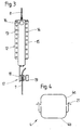
- Fig. 3
- ein im Gehäuse angeordneter Federspeicher mit einer Kupplung;
- Fig. 4
- den Gehäusefortsatz, bestehend aus einer ersten und einer zweiten Gehäuseschale.
- Wird mit 1 ein Gehäuse für einen Schaltzug 7 zum Schalten der Gangstufen einer Getriebenabe für ein Fahrrad bezeichnet, so besteht dieses aus einem Antriebsgehäuse 3 und einem Gehäusefortsatz 4. Während das Antriebsgehäuse 3 um ein Schaltrad 2 der Getriebenabe herum angeordnet und dort fixiert ist, ist der Gehäusefortsatz über ein Gelenk 5 am Antriebsgehäuse 3 beweglich gelagert, wobei ein Seilzug 8, der am Schaltrad 2 befestigt ist, durch eine Seilführung 5c mit einem Federspeicher 12 in Verbindung steht, der gemeinsam mit einer Kupplung 17 im Gehäusefortsatz untergebracht ist. Mit der Kupplung 17 wird über eine Klemmeinrichtung 18 und einer Klemmschraube 19 der Schaltzug 7 mit dem Federspeicher 12 und somit mit dem Seilzug 8 verbunden, womit eine mechanische Steuerleitung zu einer hier nicht dargestellten Handbetätigung für den Fahrer des Fahrrades an der Lenkstange hergestellt wäre. Der Schaltzug 7 verläßt den Gehäusefortsatz 4 durch eine Einstellschraube 10 in einem Gewinde 11, wobei sich eine Seilhülle 9 gegen die Einstellschraube 10 abstützt. Die als Gegenhalter für die Seilhülle 9 gedachte Einstellschraube 10 kann durch Drehung im Gewinde 11 derart verstellt werden, daß der Schaltzug in seiner Länge relativ zur Seilhülle 9 einstellbar wird.
- Das Gelenk 5 zwischen dem Antriebsgehäuse 3 und dem Gehäusefortsatz 4 ist als Kugelgelenk mit einer äußeren Lagerschale 5a und einer inneren Lagerschale 5b ausgebildet, so daß der Schaltzug am Fahrrad, beispielsweise an einer Kettenstrebe des Hinterbaus des Fahrradrahmens, derart verlegt werden kann, daß das Antriebsgehäuse bei der Montage der Nabe bereits grob fixiert wird, während unter Inanspruchnahme einer gewissen Auslenkung durch das Gelenk 5 der Gehäusefortsatz 4 nach Befestigung des Schaltzuges 7 sich in dessen Zugrichtung einstellt.
- Gegen das Eindringen von Schmutz im Bereich des Gelenkes 5 ist eine Manschette 6 vorgesehen, die den Ausgang des Antriebsgehäuses wie auch den Eingang zum Gehäusefortsatz umfaßt. Da der Gehäusefortsatz 4 aus fertigungstechnischen Gründen aus einer ersten Gehäuseschale 4a und einer zweiten Gehäuseschale 4b besteht, die miteinander über mindestens eine Formschlußverbindung 21 zusammengehalten werden, ist es von Vorteil, daß die Manschette 6 diese Teile zusammenhalten und abdichten hilft. Als weiteren Vorteil kann die Tatsache gewertet werden, daß alle Gehäuseteile 3,4a und 4b aus Kunststoff gefertigt sind, da die Herstellungsmethoden von Kunststoff eine Vielfalt von Formgebungsmöglichkeiten erlauben. Wie bereits erwähnt, nimmt der Gehäusefortsatz 4 den Seilzug 8, den Federspeicher 12 mit der Kupplung 17 und den daran angeschlossenen Schaltzug 7 auf, wobei der Federspeicher 12 aus einem Außenrohr 13, welches über einen Nippel 16 mit dem Seilzug 8 verbunden ist, einer Feder 14 und einem Innenrohr 15 besteht, welches mit der Klemmeinrichtung 18 der Kupplung 17 in Verbindung steht. Wenn nun beim Schalten eine Zugkraft durch den Schaltzug 7 auf den Federspeicher 12 geleitet wird, so wird die Kraft unmittelbar an den Seilzug 8 weitergegeben, der das Schaltrad 2 bewegt. Im Falle von Schaltwiderständen innerhalb der Getriebenabe könnte es möglich seien, daß das Schaltrad 2 vorübergehend blockiert ist, der Schaltzug 7 aber vom Fahrradfahrer betätigt wird. In diesem Fall bewegen sich das Innenrohr 15 und das Außenrohr 13 gegeneinander und spannen die Feder 14 solange vor, bis der Widerstand in der Getriebenabe abgebaut ist und das Schaltrad 2 einer Bewegung des Seilzuges 8 folgen kann. Beim Entspannen der Feder wird die Schaltung des gewünschten Ganges zeitlich verschoben eingeleitet.
- In Fig. 4 wird gezeigt, wie der Gehäusefortsatz 4 von der ersten Gehäuseschale 4a und der zweiten Gehäuseschale 4b gebildet wird. Zwei Formschlußverbindungen 21 halten die Gehäuseschalen 4a und 4b in ihrer gegenseitigen Position fest. An einer der beiden Gehäuseschalen 4a oder 4b kann eine Befestigung 20 angeordnet sein, mit Hilfe derer der Gehäusefortsatz 4 an einer Strebe des Hinterbaus des Fahrrades zur Vermeidung von Klappergeräuschen befestigt sein kann.
Claims (5)
- Gehäuse (1) für die Aufnahme eines Betätigungszuges (7) zum Anbau an eine Fahrradgetriebe, insbesondere an eine Mehrgangnabe im Hinterrad mit einem Schaltrad (2), das koaxial zur Nabenachse an einem Ende der Nabe angeordnet ist und über eine Fernbedienung mit einem vom Fahrer während der Fahrt bedienbaren Steuerorgan in Verbindung steht, wobei die Fernbedienung über einen Bowdenzug, bestehend aus einem Seilzug (8) und einer Seilhülle (9), die sich über eine Einstellschraube (10) am Gehäusefortsatz (4) abstützt,
dadurch gekennzeichnet,
daß das Gehäuse (1) ein Antriebsgehäuse (3) zur Abdeckung des Schaltrades (2) und einen rohrförmigen Gehäusefortsatz (4) zur Aufnahme des Seilzuges (8) und eine Betätigungszuges (7) aufweist, wobei das Antriebsgehäuse (3) mit dem Gehäusefortsatz (4) über eine Gelenk (5) mit einer Seilführung (5c) verbunden ist, während im Gehäusefortsatz (4) ein Federspeicher (12) und eine Kupplung (17) untergebracht sein können. - Gehäuse nach Anspruch 1,
dadurch gekennzeichnet,
daß der Gehäusefortsatz (4) aus einer ersten Gehäuseschale (4a) und einer zweiten Gehäuseschale (4b) besteht, wobei die Gehäuseschalen (4a,4b) miteinander über mindestens eine Formschlußverbindung (21) verbunden sind. - Gehäuse nach einem der Ansprüche 1 oder 2,
dadurch gekennzeichnet,
daß die erste Gehäuseschale (4a) und die zweite Gehäuseschale (4b) mit ihren Enden eine äußere Lagerschale (5a) bilden, die eine am Antriebsgehäuse (3) angeformte innere Lagerstelle (5b) umschließt. - Gehäuse nach Anspruch 3,
dadurch gekennzeichnet,
daß das Gelenk (5) mit einer Manschette (6) abgedeckt ist. - Gehäuse nach einem der Ansprüche 1 bis 4,
dadurch gekennzeichnet,
daß mindestens eines der Teile des Gehäuses (1), nämlich die erste Gehäuseschale (4a), die zweite Gehäuseschale (4b) sowie das Antriebsgehäuse (3) aus Kunststoff bestehen.
Applications Claiming Priority (2)
| Application Number | Priority Date | Filing Date | Title |
|---|---|---|---|
| DE29608010U | 1996-05-03 | ||
| DE29608010U DE29608010U1 (de) | 1996-05-03 | 1996-05-03 | Gehäuse für einen Betätigungszug zum Schalten der Gangstufen eines Fahrradgetriebes |
Publications (3)
| Publication Number | Publication Date |
|---|---|
| EP0805104A2 true EP0805104A2 (de) | 1997-11-05 |
| EP0805104A3 EP0805104A3 (de) | 1998-12-02 |
| EP0805104B1 EP0805104B1 (de) | 2003-04-09 |
Family
ID=8023474
Family Applications (1)
| Application Number | Title | Priority Date | Filing Date |
|---|---|---|---|
| EP97102747A Expired - Lifetime EP0805104B1 (de) | 1996-05-03 | 1997-02-20 | Gehäuse für einen Betätigungszug zum Schalten der Gangstufen eines Fahrradgetriebes |
Country Status (3)
| Country | Link |
|---|---|
| US (1) | US5916329A (de) |
| EP (1) | EP0805104B1 (de) |
| DE (2) | DE29608010U1 (de) |
Cited By (6)
| Publication number | Priority date | Publication date | Assignee | Title |
|---|---|---|---|---|
| EP1388491A2 (de) | 2002-08-08 | 2004-02-11 | SRAM Deutschland GmbH | Seilzugverbindung |
| US6862949B2 (en) | 2002-12-05 | 2005-03-08 | Shimano, Inc. | Conduit cover for bicycle |
| US7331255B2 (en) | 2001-09-21 | 2008-02-19 | Petrak Gregory H | Method and apparatus for tensioning an emergency brake system on a vehicle |
| US7331254B2 (en) | 2001-09-21 | 2008-02-19 | Petrak Gregory H | Method and apparatus for tensioning an emergency brake system on a vehicle |
| US7819042B2 (en) | 2007-07-31 | 2010-10-26 | Petrak Gregory H | System and method for tensioning an emergency brake system |
| US9144897B2 (en) | 2012-04-25 | 2015-09-29 | Innovative System Solutions, Inc | Apparatus, system and method for tensioning an emergency brake system |
Families Citing this family (2)
| Publication number | Priority date | Publication date | Assignee | Title |
|---|---|---|---|---|
| US6349614B1 (en) | 1998-11-06 | 2002-02-26 | Shimano, Inc. | Bicycle cable connector for splicing two cables in series |
| US6324938B1 (en) | 2000-02-28 | 2001-12-04 | Shimano, Inc. | Locking bicycle cable connecting apparatus |
Citations (3)
| Publication number | Priority date | Publication date | Assignee | Title |
|---|---|---|---|---|
| US4052914A (en) * | 1975-01-25 | 1977-10-11 | Xenoah Co. | Internally accommodated speed change mechanism applicable to a bicycle, etc. |
| DE3203197A1 (de) * | 1982-01-30 | 1983-08-04 | Fichtel & Sachs Ag, 8720 Schweinfurt | Mehrgang-freilaufnabe fuer fahrraeder in steckachs-ausfuehrung |
| EP0661204A1 (de) * | 1992-05-21 | 1995-07-05 | FICHTEL & SACHS AG | Betätigungsvorrichtung für Kombination mit einer Mehrgang-Fahrradnabe |
Family Cites Families (2)
| Publication number | Priority date | Publication date | Assignee | Title |
|---|---|---|---|---|
| JP3184230B2 (ja) * | 1990-12-28 | 2001-07-09 | 株式会社シマノ | 内装変速機 |
| DE4221728A1 (de) * | 1992-07-02 | 1994-01-05 | Fichtel & Sachs Ag | Umlenker für Mehrgangnaben für Fahrräder oder dergleichen |
-
1996
- 1996-05-03 DE DE29608010U patent/DE29608010U1/de not_active Expired - Lifetime
-
1997
- 1997-02-20 DE DE59709738T patent/DE59709738D1/de not_active Expired - Fee Related
- 1997-02-20 EP EP97102747A patent/EP0805104B1/de not_active Expired - Lifetime
- 1997-05-02 US US08/850,088 patent/US5916329A/en not_active Expired - Fee Related
Patent Citations (3)
| Publication number | Priority date | Publication date | Assignee | Title |
|---|---|---|---|---|
| US4052914A (en) * | 1975-01-25 | 1977-10-11 | Xenoah Co. | Internally accommodated speed change mechanism applicable to a bicycle, etc. |
| DE3203197A1 (de) * | 1982-01-30 | 1983-08-04 | Fichtel & Sachs Ag, 8720 Schweinfurt | Mehrgang-freilaufnabe fuer fahrraeder in steckachs-ausfuehrung |
| EP0661204A1 (de) * | 1992-05-21 | 1995-07-05 | FICHTEL & SACHS AG | Betätigungsvorrichtung für Kombination mit einer Mehrgang-Fahrradnabe |
Cited By (7)
| Publication number | Priority date | Publication date | Assignee | Title |
|---|---|---|---|---|
| US7331255B2 (en) | 2001-09-21 | 2008-02-19 | Petrak Gregory H | Method and apparatus for tensioning an emergency brake system on a vehicle |
| US7331254B2 (en) | 2001-09-21 | 2008-02-19 | Petrak Gregory H | Method and apparatus for tensioning an emergency brake system on a vehicle |
| US8051745B2 (en) | 2001-09-21 | 2011-11-08 | Petrak Gregory H | Method and apparatus for tensioning an emergency brake system on a vehicle |
| EP1388491A2 (de) | 2002-08-08 | 2004-02-11 | SRAM Deutschland GmbH | Seilzugverbindung |
| US6862949B2 (en) | 2002-12-05 | 2005-03-08 | Shimano, Inc. | Conduit cover for bicycle |
| US7819042B2 (en) | 2007-07-31 | 2010-10-26 | Petrak Gregory H | System and method for tensioning an emergency brake system |
| US9144897B2 (en) | 2012-04-25 | 2015-09-29 | Innovative System Solutions, Inc | Apparatus, system and method for tensioning an emergency brake system |
Also Published As
| Publication number | Publication date |
|---|---|
| US5916329A (en) | 1999-06-29 |
| DE59709738D1 (de) | 2003-05-15 |
| EP0805104A3 (de) | 1998-12-02 |
| DE29608010U1 (de) | 1996-07-25 |
| EP0805104B1 (de) | 2003-04-09 |
Similar Documents
| Publication | Publication Date | Title |
|---|---|---|
| DE602004011750T2 (de) | Fahrradgangschaltung | |
| DE69824369T3 (de) | Einstellvorrichtung für Bowdenzug | |
| DE69632497T2 (de) | Schutzkappe für Fahrradkabel | |
| DE60029148T3 (de) | Hilfsschaltvorrichtung in einer Fahrradgangschaltung | |
| DE60224156T2 (de) | Steuervorrichtung für eine Fahrradschaltvorrichtung | |
| DE4413610A1 (de) | Steuereinrichtung einer Fahrrad-Gangschaltung | |
| EP1157921B1 (de) | Integrierter Drehgriffschalter | |
| DE19651577C2 (de) | Drehgriffschalter für Fahrradgetriebe | |
| DE69824393T2 (de) | Schaltgriff für fahrräder mit veränderlicher mechanischer übersetzung | |
| DE2542373A1 (de) | Fahrradgangschaltung | |
| DE60027129T2 (de) | Vorrichtung zum Schützen eines Kabels | |
| DE102012201657A1 (de) | Zweifachschalteinheit für ein Fahrrad | |
| DE4337377A1 (de) | Schalthebelbaugruppe für ein Getriebe eines Kraftfahrzeugs | |
| DE3821792A1 (de) | Hinterrad-kettenumwerfer fuer eine fahrrad-kettenschaltung | |
| EP0805104B1 (de) | Gehäuse für einen Betätigungszug zum Schalten der Gangstufen eines Fahrradgetriebes | |
| EP0686552B2 (de) | Drehgriff zur Betätigung von Fahrradgangschaltungen | |
| DE102004048114B4 (de) | Radnabenanordnung | |
| DE3215426A1 (de) | Betaetigungseinrichtung fuer gangwechseleinrichtung am lenker eines fahrrades oder dergleichen | |
| DE69730001T3 (de) | Steuerungseinrichtung für eine Fahrradgangschaltung | |
| DE2723869A1 (de) | Schalter fuer fahrrad-gangschaltnabe | |
| EP1125836B1 (de) | Schalter zur Betätigung eines Getriebes an einem Fahrrad | |
| EP0806340A2 (de) | Mehrgangnabe mit Rücktrittbremse für Fahrräder | |
| DE4420125C2 (de) | Drehgriffschalter für Fahrräder | |
| EP0577129B1 (de) | Betätigungseinrichtung für eine Mehrgang-Fahrradnabe | |
| DE3215427A1 (de) | Betaetigungseinrichtung fuer gangwechseleinrichtung am lenker eines fahrrades oder dergleichen |
Legal Events
| Date | Code | Title | Description |
|---|---|---|---|
| PUAI | Public reference made under article 153(3) epc to a published international application that has entered the european phase |
Free format text: ORIGINAL CODE: 0009012 |
|
| AK | Designated contracting states |
Kind code of ref document: A2 Designated state(s): DE FR GB NL SE |
|
| RAP1 | Party data changed (applicant data changed or rights of an application transferred) |
Owner name: MANNESMANN SACHS AKTIENGESELLSCHAFT |
|
| RAP1 | Party data changed (applicant data changed or rights of an application transferred) |
Owner name: SRAM DEUTSCHLAND GMBH |
|
| PUAL | Search report despatched |
Free format text: ORIGINAL CODE: 0009013 |
|
| AK | Designated contracting states |
Kind code of ref document: A3 Designated state(s): DE FR GB NL SE |
|
| 17P | Request for examination filed |
Effective date: 19990318 |
|
| GRAH | Despatch of communication of intention to grant a patent |
Free format text: ORIGINAL CODE: EPIDOS IGRA |
|
| GRAH | Despatch of communication of intention to grant a patent |
Free format text: ORIGINAL CODE: EPIDOS IGRA |
|
| GRAA | (expected) grant |
Free format text: ORIGINAL CODE: 0009210 |
|
| AK | Designated contracting states |
Designated state(s): DE FR GB NL SE |
|
| PG25 | Lapsed in a contracting state [announced via postgrant information from national office to epo] |
Ref country code: GB Free format text: LAPSE BECAUSE OF FAILURE TO SUBMIT A TRANSLATION OF THE DESCRIPTION OR TO PAY THE FEE WITHIN THE PRESCRIBED TIME-LIMIT Effective date: 20030409 |
|
| REG | Reference to a national code |
Ref country code: GB Ref legal event code: FG4D Free format text: NOT ENGLISH |
|
| PG25 | Lapsed in a contracting state [announced via postgrant information from national office to epo] |
Ref country code: SE Free format text: LAPSE BECAUSE OF FAILURE TO SUBMIT A TRANSLATION OF THE DESCRIPTION OR TO PAY THE FEE WITHIN THE PRESCRIBED TIME-LIMIT Effective date: 20030709 |
|
| GBV | Gb: ep patent (uk) treated as always having been void in accordance with gb section 77(7)/1977 [no translation filed] |
Effective date: 20030409 |
|
| ET | Fr: translation filed | ||
| PLBE | No opposition filed within time limit |
Free format text: ORIGINAL CODE: 0009261 |
|
| STAA | Information on the status of an ep patent application or granted ep patent |
Free format text: STATUS: NO OPPOSITION FILED WITHIN TIME LIMIT |
|
| 26N | No opposition filed |
Effective date: 20040112 |
|
| PGFP | Annual fee paid to national office [announced via postgrant information from national office to epo] |
Ref country code: NL Payment date: 20090217 Year of fee payment: 13 Ref country code: DE Payment date: 20090227 Year of fee payment: 13 |
|
| PGFP | Annual fee paid to national office [announced via postgrant information from national office to epo] |
Ref country code: FR Payment date: 20090213 Year of fee payment: 13 |
|
| REG | Reference to a national code |
Ref country code: NL Ref legal event code: V1 Effective date: 20100901 |
|
| REG | Reference to a national code |
Ref country code: FR Ref legal event code: ST Effective date: 20101029 |
|
| PG25 | Lapsed in a contracting state [announced via postgrant information from national office to epo] |
Ref country code: NL Free format text: LAPSE BECAUSE OF NON-PAYMENT OF DUE FEES Effective date: 20100901 Ref country code: FR Free format text: LAPSE BECAUSE OF NON-PAYMENT OF DUE FEES Effective date: 20100301 |
|
| PG25 | Lapsed in a contracting state [announced via postgrant information from national office to epo] |
Ref country code: DE Free format text: LAPSE BECAUSE OF NON-PAYMENT OF DUE FEES Effective date: 20100901 |