EP0805064A2 - Sitzkissen und Verfahren zum Giessen einer Sitzeinheit mit einem Sitzkissen - Google Patents
Sitzkissen und Verfahren zum Giessen einer Sitzeinheit mit einem Sitzkissen Download PDFInfo
- Publication number
- EP0805064A2 EP0805064A2 EP97302932A EP97302932A EP0805064A2 EP 0805064 A2 EP0805064 A2 EP 0805064A2 EP 97302932 A EP97302932 A EP 97302932A EP 97302932 A EP97302932 A EP 97302932A EP 0805064 A2 EP0805064 A2 EP 0805064A2
- Authority
- EP
- European Patent Office
- Prior art keywords
- layer
- cushion
- seat unit
- base structure
- mold section
- Prior art date
- Legal status (The legal status is an assumption and is not a legal conclusion. Google has not performed a legal analysis and makes no representation as to the accuracy of the status listed.)
- Withdrawn
Links
Images


Classifications
-
- B—PERFORMING OPERATIONS; TRANSPORTING
- B60—VEHICLES IN GENERAL
- B60N—SEATS SPECIALLY ADAPTED FOR VEHICLES; VEHICLE PASSENGER ACCOMMODATION NOT OTHERWISE PROVIDED FOR
- B60N2/00—Seats specially adapted for vehicles; Arrangement or mounting of seats in vehicles
- B60N2/70—Upholstery springs ; Upholstery
- B60N2/7017—Upholstery springs ; Upholstery characterised by the manufacturing process; manufacturing upholstery or upholstery springs not otherwise provided for
Definitions
- the invention relates generally to seat cushions and methods of molding seat units including seat cushions, and more particularly to a seat cushion comprised of a mesh of plastic filament wherein multiple cushion layers comprised of plastic filament may be combined, each cushion layer having a different density, as well as a method for molding the perimeter of a seat cushion with a seat base structure.
- seat units used in furniture or in automobiles have internal cushioning comprised of expanded urethane or ethylene.
- the expanded urethane or ethylene cushion compresses, thus resulting in the cushion becoming more dense. This increased density results in less circulation of air throughout the cushion.
- the seating area of the seat unit is more likely to become overheated, resulting in the seated person becoming uncomfortable.
- a woven seat covering is supported across a base structure with the perimeter of the woven seat covering secured to the base structure at spaced positions by staples, sewing, or the like.
- the tension in the covering is thus maintained only by the stapled or sewed strands of the woven material. Under load application, these strands soon become weakened and break or tear loose.
- these seat units have a relatively short service life with a lack of firmness and support for their intended purpose.
- a superior seat unit construction is one where a pretensioned woven seat covering is molded in with a base structure.
- An effective method for molding a composite article such as this is disclosed in U.S. Patent No. 4,743,323. While the method of molding in the woven seat covering helps to make the securement of the covering more durable, the problem of inadequate air circulation throughout the seat cushion of the seat unit is not rectified. This is because in order for a seat cushion to have adequate firmness, it has been necessary for the cushion to be so dense that inadequate air circulation therethrough results once a load is applied to the seating area.
- the aim of the invention is to overcome one or more of the difficulties encountered in the prior art.
- a seat unit comprising: (a) a base structure; (b) a cover layer secured to the base structure; and (c) a cushion layer between the base structure and the cover layer, said cushion layer comprised of a mesh of plastic filament.
- a seat unit comprising: (a) a base structure; (b) a cover layer secured to the base structure; and (c) at least two cushion layers between the base structure and the cover layer, at least two of said cushion layers comprising a mesh of plastic filament, at least one of the cushion layers having a different density than another cushion layer.
- a method of molding a seat unit comprising the steps of: (a) providing a mold unit, said mold unit having a male mold section and a female mold section which, on being brought together, form a mold cavity; (b) supporting at least one cushion layer comprising plastic filament across an open side of said male mold section; (c) bringing said male mold section and said female mold section together so that said female mold section engages and stretches said cushion layer supported across said open side of said male mold section; (d) injecting a plastic material into said mold cavity so that said plastic material bonds with said cushion layer; and (e) removing said resultant seat unit from said mold unit.
- a method of molding a seat unit comprising the steps of: (a) providing a mold unit, said mold unit having a male mold section and a female mold section which, on being brought together, form a mold cavity; (b) supporting a plurality of cushion layers across an open side of said male mold section, where at least one cushion layer is of a different density from another cushion layer; (c) bringing said male mold section and said female mold section together so that said female mold section engages and stretches said cushion layer supported across said open side of said male mold section; (d) injecting a plastic material into said mold cavity so that said plastic material bonds with said cushion layer; and (e) removing said resultant seat unit from said mold unit.
- Another advantage of the present invention is to provide a method of making a seat unit where the seat unit has cushioning that not only has adequate firmness, but air circulation therethrough after a load is applied.
- Yet another advantage of the present invention is to provide a seat unit in which cushioning is molded in with a base structure.
- a further advantage of the present invention is to provide a method of making a seat unit in which cushioning is molded in with a base structure.
- Another advantage of the present invention is to provide a seat unit having multiple layers of cushioning where the multiple layers are of differing density thereby allowing the cushion to have a desired firmness as well as air circulation therethrough after a load is applied.
- Still another advantage of the present invention is to provide a method of molding in multiple layers of cushioning with a base structure where the multiple layers are of differing density thereby allowing the cushion to have a desired firmness as well as air circulation therethrough after a load is applied.
- a seat unit comprising a base structure and at least one cushion layer comprised of a mesh of plastic filament.
- the cushion layer not only provides adequate firmness, but has air circulation therethrough.
- the perimeter of the cushion layer and/or the perimeter of a cover layer may be molded in with a plastic base structure, and there may be multiple cushion layers where each layer has a different density.
- the multiple layers of cushioning where each layer has a different density further allow the seat unit to have both a specifically desired firmness and air circulation therethrough.
- the invention also provides a method for molding in at least one cushion layer comprised of plastic filament with a base structure as well as molding in a spring layer and a cover layer.
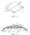
- FIG. 1 A seat unit 10 is generally shown in FIG. 1.
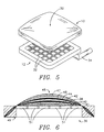
- the seat unit 10 is provided as shown in FIG. 2 where the seat unit 10 includes a base structure 12 for supporting cushion layers 14, 16 and 18 sandwiched between a spring layer 20 and a cover layer 22.
- FIG. 3 is an exploded perspective view of the seat unit 10 of FIG. 2 showing the base structure 12, cushion layers 14, 16 and 18, spring layer 20 and cover layer 22.
- the spring layer 20, the cushion layers 14, 16 and 18, and the cover layer 22 are molded in with the base structure 12.
- the first layer closest to the base structure 12 is the spring layer 20.
- the spring layer 20 may be comprised of any material which adds firmness to the cushion layers 14, 16 and 18.
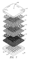
- first cushion layer 18 having a high density.
- first cushion layer 18 may be comprised of a mesh of strands of plastic filament 28 as shown in FIGS. 3 and 4c where the plastic filament 28 has a relatively large diameter as shown in FIG. 4c'.
- second cushion layer 16 Located on top of the first cushion layer 18 is a second cushion layer 16 having a medium density.
- the second cushion layer 16 may be comprised of a mesh of strands of plastic filament 26 as shown in FIGS. 3 and 4b, where the plastic filament 26 has a medium diameter as shown in FIG.
- the third cushion layer 14 Located on top of the second cushion layer 16 is a third cushion layer 14 having a relatively low density.
- the third cushion layer 14 may be comprised of a mesh of strands of plastic filament 24 as shown in FIGS. 3 and 4a, where the plastic filament 24 has a relatively small diameter as shown in FIG. 4a' and where there is less plastic filament 24 per cubic inch than of plastic filament 26 per cubic inch within the second cushion layer 16 and of plastic filament 28 per cubic inch within the first cushion layer 18.
- the plastic filament 24, 26 and 28 of cushion layers 14, 16 and 18 may be a continuous hot melt filament fiber or an extruded string-like material which after being generally shaped into the cushion layers 14, 16 and 18, is deformed through a deforming process such as punching.
- the spring layer 20 supports the cushion layers 14, 16 and 18. Space between the plastic filament 24, 26 and 28 within each cushion layer 14, 16 and 18 allows air to move through the cushion layers 14, 16 and 18, thus resulting in the seating area 30 being less likely to overheat.
- the base structure 12 is provided with air holes 32 such that the seat unit 10 may be positioned over an air supply line 34 as shown in FIG. 5 thus providing for maximum air circulation through the cushion layers 14, 16 and 18 and to the seating area 30.
- One alternative to the preferred embodiment is to provide a seat unit 36 wherein a first barrier layer 38 is between cushion layers 40 and 42, and a second barrier layer 44 is between cushion layers 42 and 46 as shown in FIGS. 6 and 7.
- Cushion layers 40, 42 and 46 may be identical to cushion layers 18, 16 and 14, respectively, which were described above with relation to seat unit 10 shown in FIGS. 2 and 3.
- the cushion layers 40, 42 and 46, barrier layers 38 and 44, a spring layer 41, and a cover layer 47 may be molded in with a base structure 49.
- the barrier layers 38 and 44 may be comprised of a textile, and the barrier layers 38 and 44 function to minimize penetration amongst the cushion layers 40, 42 and 46 when a load (not shown) is applied to a seating area 48 of the seat unit 36, thus maintaining the integrity of the difference in densities between the cushion layers 40, 42 and 46. Any or all of the cushion layers 40, 42 and 46 may be adhered, such as by flame adhesion, to the adjacent barrier layer 38 or 44. As an alternative to providing barrier layers 38 and 44, each cushion layer 40, 42 and 46 may have a melted or otherwise prepared densified side. Much like the base structure 12 shown in Fig. 2, the base structure 49 of Fig. 6 may have air holes 51 such that the seat unit 36 may be positioned over the air supply line 34 much like the seat unit 10 shown in Fig. 5.
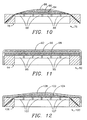
- a seat unit 50 may be provided such that the seat unit 50 is of a more conventional construction where a cover layer 52 is affixed to a base structure 54 through conventional means and neither cushion layers 56, 58, and 60 nor a spring layer 62 is molded in with the base structure 54.
- the base structure 54 shown in Fig. 8 may be provided with air holes 61 so that the seat unit 50 may be positioned over the air supply line 34 much like the seat unit 10 as shown in Fig. 5.
- a seat unit 64 as schematically shown in FIG. 9, where only a spring layer 66 and cushion layers 68, 70 and 72 are molded in with a base structure 74 while a cover layer 75 is not molded in, but is instead affixed to the base structure 74 through conventional means.
- the base structure 74 may also be provided with air holes 71 so that the seat unit 64 may be positioned over the air supply line 34 much like the seat unit 10 as shown in Fig. 5.
- each cushion layer has a different density. For example, it is possible to vary the diameters of the plastic filament and/or vary the amount of filament per cubic inch.
- One of ordinary skill in the art would undoubtedly realize still other possible variations of the present invention comprising multiple cushion layers.
- the seat unit 76 includes a base structure 78 for supporting a single cushion layer 80 comprised of a mesh of strands of plastic filament much like any of the cushion layers 14, 16 or 18 shown in Figs. 4a, 4b or 4c.
- the cushion layer 80 is sandwiched between a spring layer 84 and a cover layer 86, and the spring layer 84, the cushion layer 80, and the cover layer 86 may be molded in with the base structure 78.
- the base structure 78 may have air holes 88 such that the seat unit 76 may be positioned over the air supply line 34 in much the same manner as the seat unit 10 is positioned over the air supply line 34 as shown in FIG. 5, thus providing for maximum air circulation through the cushion layer 80.
- a seat unit 90 may be provided such that the seat unit 90 is of a more conventional construction where a cover layer 92 is affixed to a base structure 94 through conventional means and neither a cushion layer 96 nor a spring layer 98 is molded in with the base structure 94.
- the base structure 94 may also be provided with air holes 95 as shown in Fig. 11.
- a seat unit 100 as schematically shown in FIG. 12 where only a spring layer 102 and a cushion layer 104 are molded in with a base structure 106 while a cover layer 108 is not molded in, but is instead affixed to the base structure 106 through conventional means.
- the base structure 106 may be provided with air holes 107 as shown in Fig. 12.
- One of ordinary skill in the art would undoubtedly realize still other possible variations of the present invention including a single cushion layer comprised of plastic filament.
- a plastic injection molding process such as the process described below may be utilized in order to construct any of the seat units described above.
- the seat unit 10 of FIG. 2 may be constructed by utilizing the plastic injection molding process described below.
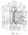
- a mold unit 110 having a stationery male mold section 112 and a moveable female mold section 114.
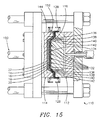
- the mold sections 112 and 114 When the mold sections 112 and 114 are in their closed positions, as shown in FIG. 15, the mold sections 112 and 114 form a mold cavity 116 for forming the base structure 12 of the seat unit 10 shown in FIG. 2.
- the mold sections 112 and 114 are in their open positions as shown in FIG.
- the cushion layers 14, 16 and 18 and the spring layer 20, shown exaggerated for clarity, are placed across an open side 118 of the male mold section 112 with their outer edges 120, 122, 124 and 126 secured outside the male mold section 112 by suitable clamping means 128 as shown in FIG. 14.
- the spring layer 20 has a central portion 130 positioned against protrusions 132 on a projected central portion 134 of the male mold section 112, and the cushion layers 14, 16 and 18 and the spring layer 20 have inclined sections 136, 138, 140 and 142 extending from the projected central portion 134 of the male mold section 112 to the clamping means 128.
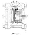
- a plastic material 170 is then injected into the mold cavity 116 through a gate opening 172 from an injection nozzle 174 to fill the mold cavity 116 as shown in FIG. 16 and surround the protrusions 132 on the projected central portion 134 of the male mold section 112.
- the inner portions 158, 160, 162, and 164 of the inclined sections 136, 138, 140 and 142 of the cushion layers 14, 16 and 18 and the spring layer 20 are imbedded within the injected plastic material 170 along with the inclined sections 168 of the cover layer 22.
- the base structure 12 has air holes 32 as a result of the plastic material 170 having surrounded the protrusions 132 in the mold cavity 116, and the cover layer 22, the cushion layers 14, 16 and 18, and the spring layer 20 are molded in with the base structure 12. Subsequently, the cushion layers 14, 16 and 18 and the spring layer 20 are trimmed at the junction of the outer 150, 152, 154 and 156 and inner portions 158, 160, 162 and 164 of the inclined sections 136, 138, 140 and 142 of the layers 14, 16, 18 and 20, and the cover layer 22 is trimmed at the junction of the outer sections 166 and inclined sections 168. Thereafter, the formed seat unit 10 may be positioned over an air supply line 34 as shown in FIG.
- the male mold section 112 may be shaped such that the resulting base structure 12 has a true open central area, whereby a grid (not shown) is later attached to the base structure 12 to provide air holes 32 underneath the seat unit 10.
- each cushion layer 40, 42 and 46 may have a melted or otherwise prepared densified side (not shown).
- the seat unit 10 as shown in FIG. 2 where the spring layer 20, the cushion layers 14, 16 and 18, and the cover layer 22 are molded in with the base structure 12, it is possible to provide additional alternative methods of the present invention comprising multiple cushion layers.
- the base structure 54 alone may be molded by omitting the steps of securing any layers against either mold section 112 or 114, and upon removing the base structure 54 from the mold unit 110, the cover layer 52 may be affixed to the base structure 54 through conventional means so that the cushion layers 56, 58 and 60 and the spring layer 62 are sandwiched between the base structure 54 and the cover layer 52.
- the seat unit 64 schematically shown in FIG.
- a seat unit having a single cushion layer comprised of plastic filament instead of molding a seat unit having multiple cushion layers, it is possible to mold a seat unit having a single cushion layer comprised of plastic filament.
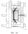
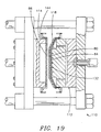
- a plastic injection molding process such as the process described below may be utilized in order to construct the seat unit 76 of FIG. 10.
- a single cushion layer 80 comprised of a mesh of strands of plastic filament and a spring layer 84, shown exaggerated for clarity are placed across the open side 118 of the male mold section 112, and the cover layer 86 is placed across the open side 144 of the female mold section 114 as shown in FIG. 19 in much the same manner as described above with relation to FIG. 14.
- cover layer 86 across the male mold section 112 along with the cushion layer 80 and the spring layer 84, or it is possible to secure the cushion layer 80 and the spring layer 84 across the female mold section 114 along with the cover layer 86.
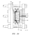
- the seat unit 76 may be positioned over the air supply line 34 in much the same manner as the seat unit 10 is positioned over the air supply line 34 as shown in FIG. 5 thus providing for maximum air circulation through the cushion layer 80.
- the cover layer 92 may be affixed to the base structure 94 through conventional means so that the cushion layer 96 and the spring layer 98 are sandwiched between the base structure 94 and the cover layer 92. Additionally, it is possible to mold the seat unit 100 schematically shown in FIG. 12, by molding in only the spring layer 102 and the cushion layer 104 with the base structure 106, while the cover layer 108 is subsequently affixed to the base structure 106 through conventional means after the plastic injection molding process.
- One of ordinary skill in the art would undoubtedly realize still other possible variations of the present invention comprising a single cushion layer. For example, it is possible to eliminate the spring layer from any of the molding methods described herein.
Landscapes
- Engineering & Computer Science (AREA)
- Manufacturing & Machinery (AREA)
- Aviation & Aerospace Engineering (AREA)
- Transportation (AREA)
- Mechanical Engineering (AREA)
- Mattresses And Other Support Structures For Chairs And Beds (AREA)
- Laminated Bodies (AREA)
- Moulds For Moulding Plastics Or The Like (AREA)
Applications Claiming Priority (2)
| Application Number | Priority Date | Filing Date | Title |
|---|---|---|---|
| US08/639,777 US5788332A (en) | 1996-04-29 | 1996-04-29 | Seat unit and cushion |
| US639777 | 1996-04-29 |
Publications (2)
| Publication Number | Publication Date |
|---|---|
| EP0805064A2 true EP0805064A2 (de) | 1997-11-05 |
| EP0805064A3 EP0805064A3 (de) | 2000-07-19 |
Family
ID=24565502
Family Applications (1)
| Application Number | Title | Priority Date | Filing Date |
|---|---|---|---|
| EP97302932A Withdrawn EP0805064A3 (de) | 1996-04-29 | 1997-04-29 | Sitzkissen und Verfahren zum Giessen einer Sitzeinheit mit einem Sitzkissen |
Country Status (2)
| Country | Link |
|---|---|
| US (1) | US5788332A (de) |
| EP (1) | EP0805064A3 (de) |
Cited By (17)
| Publication number | Priority date | Publication date | Assignee | Title |
|---|---|---|---|---|
| EP1295696A3 (de) * | 2001-09-19 | 2004-11-24 | Nhk Spring Co., Ltd. | Verfahren zum Herstellen eines Sitzes oder eines Teils eines Sitzes |
| EP2607156A1 (de) * | 2011-12-22 | 2013-06-26 | Grammer Ag | Fahrzeugsitz, Verfahren zum Herstellen eines Fahrzeugsitzpolsterteils und Verwendung eines Heißpressstempels |
| USD840724S1 (en) * | 2017-12-01 | 2019-02-19 | Davinci Ii Csj, Llc | Seat cushion |
| WO2020163212A1 (en) * | 2019-02-08 | 2020-08-13 | Gentherm Incorporated | Climate controlled insert with lattice structure |
| US11318869B2 (en) | 2018-12-06 | 2022-05-03 | Gentherm Incorporated | Single piece plenum |
| USD976614S1 (en) | 2017-12-01 | 2023-01-31 | Davinci Ii Csj, Llc | Cushion with honeycomb pattern |
| DK202370197A1 (en) * | 2022-06-14 | 2024-02-14 | Lear Corp | Extruded plastic mesh, seat assembly, cushion and/or method of forming |
| US12269384B2 (en) | 2021-03-31 | 2025-04-08 | Lear Corporation | Seat support |
| US12286045B2 (en) | 2021-12-02 | 2025-04-29 | Lear Corporation | Vehicle seating system and method for producing same |
| US12286044B2 (en) | 2023-05-12 | 2025-04-29 | Lear Corporation | Method and apparatus for producing a vehicle interior component |
| US12319183B2 (en) | 2021-03-31 | 2025-06-03 | Lear Corporation | Seat support |
| US12325624B2 (en) | 2023-03-06 | 2025-06-10 | Lear Corporation | Seat assembly, cushion, and tool and method of forming |
| US12325168B2 (en) | 2021-12-20 | 2025-06-10 | Lear Corporation | System and method of making a mesh cushion |
| US12384094B2 (en) | 2022-03-08 | 2025-08-12 | Lear Corporation | Method for producing a vehicle interior component |
| US12407332B2 (en) | 2023-12-15 | 2025-09-02 | Lear Corporation | Apparatus for providing parallel filtering |
| US12454111B2 (en) | 2022-05-11 | 2025-10-28 | Lear Corporation | Tool to manufacture a cushion |
| US12479143B2 (en) | 2021-12-20 | 2025-11-25 | Lear Corporation | System and method of making a mesh cushion |
Families Citing this family (32)
| Publication number | Priority date | Publication date | Assignee | Title |
|---|---|---|---|---|
| DE19955159A1 (de) * | 1999-11-17 | 2001-05-23 | Johnson Controls Gmbh | Polsterteil, insbesondere für einen Kraftfahrzeugsitz, sowie Formwerkzeug und Verfahren zu seiner Herstellung |
| US20040012238A1 (en) * | 2000-11-21 | 2004-01-22 | Masaaki Zenba | Seat pad for vehicle |
| US6598251B2 (en) | 2001-06-15 | 2003-07-29 | Hon Technology Inc. | Body support system |
| US6983997B2 (en) * | 2001-06-29 | 2006-01-10 | Haworth, Inc. | Chair having a suspension seat assembly |
| EP1391284A1 (de) * | 2002-08-23 | 2004-02-25 | Kasai Kogyo Co., Ltd. | Schichtverbund und dessen Herstellungsverfahren |
| US10722049B2 (en) | 2016-06-28 | 2020-07-28 | Breathablebaby, Llc | Reversible crib shield system |
| US20170367497A1 (en) * | 2016-06-28 | 2017-12-28 | Breathablebaby, Llc | Porous crib shield system |
| US20170367496A1 (en) | 2016-06-28 | 2017-12-28 | Breathablebaby, Llc | Durable crib shield system |
| DE20316703U1 (de) * | 2003-10-30 | 2004-02-19 | Wu, Ching-Hsun, Wuri Hsiang | Kissen |
| US7444700B2 (en) * | 2004-10-21 | 2008-11-04 | Sears Manufacturing Co. | Seat cushion with integral cover attachment |
| US7250125B2 (en) * | 2005-03-30 | 2007-07-31 | Shiun Jiug Industrial Co., Ltd. | Method of fabricating foamed rubber member |
| USD546709S1 (en) * | 2006-03-08 | 2007-07-17 | Brooks Rosemary H | Combined pillow and alarm clock |
| US7267408B2 (en) * | 2006-05-19 | 2007-09-11 | Zhejiang Yongqiang Group Co., Ltd. | Article of rattan furniture having a seat support cushion |
| US7690732B2 (en) * | 2007-02-22 | 2010-04-06 | Series International, Llc | Molded seat assembly with flexible weaving |
| US7871039B2 (en) * | 2007-05-22 | 2011-01-18 | The Boeing Company | Modular passenger seat for an aircraft |
| CA2637973C (en) * | 2007-07-16 | 2018-02-27 | David Gellis | Utility glove |
| US9555567B2 (en) | 2007-07-16 | 2017-01-31 | Madgrip Holdings, Llc | Utility glove |
| US9498009B2 (en) | 2007-07-16 | 2016-11-22 | Madgrip Holdings, Llc | Utility glove |
| WO2009142301A1 (ja) * | 2008-05-22 | 2009-11-26 | 株式会社デルタツーリング | ビーズ発泡樹脂弾性部材、積層弾性構造体及び座席構造 |
| EP2181887B1 (de) * | 2008-10-31 | 2011-08-03 | C.R.F. Società Consortile per Azioni | Fahrzeugsitzstützkörper |
| US8087726B2 (en) * | 2009-11-04 | 2012-01-03 | Formosa Sounding Corp. | Back cushion |
| TWI527539B (zh) * | 2013-09-18 | 2016-04-01 | Solid-state gel cushions | |
| CN107000846B (zh) * | 2014-09-24 | 2021-03-12 | Be航天公司 | 带有包封舒适弹簧的座椅底板组件 |
| US9591926B2 (en) * | 2015-03-03 | 2017-03-14 | Glenn W. Harte | Prostatic relief cushion and method |
| US9993086B2 (en) | 2015-03-03 | 2018-06-12 | Glenn W. Harte | Prostatic relief cushion and method |
| US20170065093A1 (en) * | 2015-09-08 | 2017-03-09 | Mindsinsync (Hong Kong) Ltd | Cushion |
| USD789652S1 (en) | 2015-09-30 | 2017-06-20 | Madgrip Holdings, Llc | Glove |
| USD783229S1 (en) | 2015-09-30 | 2017-04-11 | Madgrip Holdings, Llc | Glove |
| US11801781B1 (en) * | 2022-04-06 | 2023-10-31 | Lear Corporation | Seat assembly |
| US12408756B1 (en) | 2022-05-27 | 2025-09-09 | Series International, Llc | Stacking chair with removable back |
| CN119546480A (zh) * | 2022-06-14 | 2025-02-28 | 李尔公司 | 挤出塑料网、座椅组件、衬垫和/或形成方法 |
| USD1073366S1 (en) * | 2023-11-08 | 2025-05-06 | Yiwu Kuanggu Trading Co., Ltd | Two-faced reversible seat cushion |
Family Cites Families (11)
| Publication number | Priority date | Publication date | Assignee | Title |
|---|---|---|---|---|
| FR1601041A (de) * | 1968-01-15 | 1970-08-03 | ||
| US3823980A (en) * | 1973-05-14 | 1974-07-16 | Blair Mfg Co | Chair |
| US3907363A (en) * | 1974-04-22 | 1975-09-23 | Steelcase Inc | Upholstery system |
| US4743323A (en) * | 1986-11-04 | 1988-05-10 | Siebolt Hettinga | Method of molding a composite article |
| JPH056824Y2 (de) * | 1986-12-02 | 1993-02-22 | ||
| US5000515A (en) * | 1989-02-14 | 1991-03-19 | Hoover Universal, Inc. | Variable density foam vehicle seat |
| US5067772A (en) * | 1990-03-29 | 1991-11-26 | Michigan Seat Company | Foam seat with insert |
| AT399488B (de) * | 1991-04-22 | 1995-05-26 | Greiner & Soehne C A | Sitzpolster, insbesondere flugzeugsitz |
| JP2842100B2 (ja) * | 1992-11-04 | 1998-12-24 | トヨタ自動車株式会社 | クッション材の製造方法 |
| US5400490A (en) * | 1993-02-26 | 1995-03-28 | Woodbridge Foam Corporation | Method of molding a seat having anchoring means connected thereto |
| US5482665A (en) * | 1994-03-18 | 1996-01-09 | General Motors Corporation | Method/apparatus for making fiber-filled cushion |
-
1996
- 1996-04-29 US US08/639,777 patent/US5788332A/en not_active Expired - Fee Related
-
1997
- 1997-04-29 EP EP97302932A patent/EP0805064A3/de not_active Withdrawn
Cited By (19)
| Publication number | Priority date | Publication date | Assignee | Title |
|---|---|---|---|---|
| EP1295696A3 (de) * | 2001-09-19 | 2004-11-24 | Nhk Spring Co., Ltd. | Verfahren zum Herstellen eines Sitzes oder eines Teils eines Sitzes |
| US7090739B2 (en) | 2001-09-19 | 2006-08-15 | Nhk Spring Co., Ltd. | Method of manufacturing a seat |
| EP2607156A1 (de) * | 2011-12-22 | 2013-06-26 | Grammer Ag | Fahrzeugsitz, Verfahren zum Herstellen eines Fahrzeugsitzpolsterteils und Verwendung eines Heißpressstempels |
| USD840724S1 (en) * | 2017-12-01 | 2019-02-19 | Davinci Ii Csj, Llc | Seat cushion |
| USD976614S1 (en) | 2017-12-01 | 2023-01-31 | Davinci Ii Csj, Llc | Cushion with honeycomb pattern |
| US11318869B2 (en) | 2018-12-06 | 2022-05-03 | Gentherm Incorporated | Single piece plenum |
| WO2020163212A1 (en) * | 2019-02-08 | 2020-08-13 | Gentherm Incorporated | Climate controlled insert with lattice structure |
| US12319183B2 (en) | 2021-03-31 | 2025-06-03 | Lear Corporation | Seat support |
| US12269384B2 (en) | 2021-03-31 | 2025-04-08 | Lear Corporation | Seat support |
| US12286045B2 (en) | 2021-12-02 | 2025-04-29 | Lear Corporation | Vehicle seating system and method for producing same |
| US12325168B2 (en) | 2021-12-20 | 2025-06-10 | Lear Corporation | System and method of making a mesh cushion |
| US12479143B2 (en) | 2021-12-20 | 2025-11-25 | Lear Corporation | System and method of making a mesh cushion |
| US12384094B2 (en) | 2022-03-08 | 2025-08-12 | Lear Corporation | Method for producing a vehicle interior component |
| US12454111B2 (en) | 2022-05-11 | 2025-10-28 | Lear Corporation | Tool to manufacture a cushion |
| DK181948B1 (en) * | 2022-06-14 | 2025-04-08 | Lear Corp | Seat support comprising a plurality of layers or regions of a plastic mesh, a seat assembly, a tool and method of forming the seat support |
| DK202370197A1 (en) * | 2022-06-14 | 2024-02-14 | Lear Corp | Extruded plastic mesh, seat assembly, cushion and/or method of forming |
| US12325624B2 (en) | 2023-03-06 | 2025-06-10 | Lear Corporation | Seat assembly, cushion, and tool and method of forming |
| US12286044B2 (en) | 2023-05-12 | 2025-04-29 | Lear Corporation | Method and apparatus for producing a vehicle interior component |
| US12407332B2 (en) | 2023-12-15 | 2025-09-02 | Lear Corporation | Apparatus for providing parallel filtering |
Also Published As
| Publication number | Publication date |
|---|---|
| US5788332A (en) | 1998-08-04 |
| EP0805064A3 (de) | 2000-07-19 |
Similar Documents
| Publication | Publication Date | Title |
|---|---|---|
| US5788332A (en) | Seat unit and cushion | |
| EP0266742B1 (de) | Verfahren zum Herstellen eines Verbundwerkstoffgegenstandes | |
| US20090321987A1 (en) | Seat cushion using vertically lapped fiber | |
| JP2024541189A (ja) | 熱可塑性繊維ウェブ構造体および自動車内装部品 | |
| GB2063065A (en) | Seat cushion | |
| US11801781B1 (en) | Seat assembly | |
| US6505570B1 (en) | Method for forming a foamed product integral with trim cover assembly | |
| EP1903914B1 (de) | Abnehmbares sitzpolster | |
| US20030098113A1 (en) | Method for forming a foamed product integral with trim cover assembly | |
| JP2611422B2 (ja) | 発泡成形品およびその補強材基布 | |
| EP0100698B1 (de) | Einschaliger Sitz mit integrierter Wattierung und Polsterung und Verfahren zu seiner Herstellung | |
| RU2342895C2 (ru) | Способ изготовления амортизирующего материала из формованного полимерного продукта (варианты) и амортизирующий материал (варианты) | |
| US5181980A (en) | Method of manufacturing skin cover for seat | |
| US20060192420A1 (en) | Furniture item and a method for attaching webbing thereto | |
| CA1281867C (en) | Method of molding a composite article | |
| JP3819527B2 (ja) | シート用クッション体およびその製造方法 | |
| US20030211304A1 (en) | Molded finished part and method of making same cross-references to related applications | |
| EP4631783A1 (de) | Polyestersitzgarnitur | |
| WO2024173295A2 (en) | Molded polyester pad and process for producing the same | |
| CN120056832A (zh) | 座椅组件和组装方法 | |
| KR20060079843A (ko) | 스프링구조 수지성형품으로 이루어진 쿠션재 및 그쿠션재의 제조방법 및 상기 제조방법에 이용되는 틀 | |
| EP1272341A1 (de) | Fertiges formteil und verfahren zur herstellung | |
| JPH0557827A (ja) | 発泡成形品用補強材 | |
| HK1021495A (en) | Method for producing a furniture element and such an element |
Legal Events
| Date | Code | Title | Description |
|---|---|---|---|
| PUAI | Public reference made under article 153(3) epc to a published international application that has entered the european phase |
Free format text: ORIGINAL CODE: 0009012 |
|
| AK | Designated contracting states |
Kind code of ref document: A2 Designated state(s): DE FR GB IT |
|
| PUAL | Search report despatched |
Free format text: ORIGINAL CODE: 0009013 |
|
| AK | Designated contracting states |
Kind code of ref document: A3 Designated state(s): DE FR GB IT |
|
| STAA | Information on the status of an ep patent application or granted ep patent |
Free format text: STATUS: THE APPLICATION HAS BEEN WITHDRAWN |
|
| 18W | Application withdrawn |
Withdrawal date: 20010212 |