EP0805040B1 - Erfassung des Tröpfchendurchflusses - Google Patents
Erfassung des Tröpfchendurchflusses Download PDFInfo
- Publication number
- EP0805040B1 EP0805040B1 EP97302697A EP97302697A EP0805040B1 EP 0805040 B1 EP0805040 B1 EP 0805040B1 EP 97302697 A EP97302697 A EP 97302697A EP 97302697 A EP97302697 A EP 97302697A EP 0805040 B1 EP0805040 B1 EP 0805040B1
- Authority
- EP
- European Patent Office
- Prior art keywords
- catcher
- vacuum
- tank
- fluid
- flow
- Prior art date
- Legal status (The legal status is an assumption and is not a legal conclusion. Google has not performed a legal analysis and makes no representation as to the accuracy of the status listed.)
- Expired - Lifetime
Links
- 238000001514 detection method Methods 0.000 title claims description 13
- 239000012530 fluid Substances 0.000 claims description 41
- 230000007704 transition Effects 0.000 claims description 8
- 230000007423 decrease Effects 0.000 claims description 6
- 238000000034 method Methods 0.000 claims description 5
- 238000012544 monitoring process Methods 0.000 claims description 3
- 230000008901 benefit Effects 0.000 description 5
- 238000007641 inkjet printing Methods 0.000 description 5
- 239000007788 liquid Substances 0.000 description 4
- 241000237858 Gastropoda Species 0.000 description 3
- 238000005259 measurement Methods 0.000 description 2
- 238000013019 agitation Methods 0.000 description 1
- 230000003247 decreasing effect Effects 0.000 description 1
- 230000003116 impacting effect Effects 0.000 description 1
- 239000007791 liquid phase Substances 0.000 description 1
- 238000012986 modification Methods 0.000 description 1
- 230000004048 modification Effects 0.000 description 1
- 238000007639 printing Methods 0.000 description 1
- 230000005514 two-phase flow Effects 0.000 description 1
- XLYOFNOQVPJJNP-UHFFFAOYSA-N water Substances O XLYOFNOQVPJJNP-UHFFFAOYSA-N 0.000 description 1
Images
Classifications
-
- B—PERFORMING OPERATIONS; TRANSPORTING
- B41—PRINTING; LINING MACHINES; TYPEWRITERS; STAMPS
- B41J—TYPEWRITERS; SELECTIVE PRINTING MECHANISMS, i.e. MECHANISMS PRINTING OTHERWISE THAN FROM A FORME; CORRECTION OF TYPOGRAPHICAL ERRORS
- B41J2/00—Typewriters or selective printing mechanisms characterised by the printing or marking process for which they are designed
- B41J2/005—Typewriters or selective printing mechanisms characterised by the printing or marking process for which they are designed characterised by bringing liquid or particles selectively into contact with a printing material
- B41J2/01—Ink jet
- B41J2/17—Ink jet characterised by ink handling
- B41J2/18—Ink recirculation systems
- B41J2/185—Ink-collectors; Ink-catchers
- B41J2002/1853—Ink-collectors; Ink-catchers ink collectors for continuous Inkjet printers, e.g. gutters, mist suction means
Definitions
- the present invention relates to continuous ink jet printing systems and, more particularly, to the detection of the fluid flow regime in the catcher vacuum port and catcher return line to the ink tank of continuous ink jet printing systems.
- electrically conductive ink is supplied under pressure to a manifold region that distributes the ink to a plurality of orifices, typically arranged in a linear array(s).
- the ink discharges from the orifices in filaments which break into droplet streams.
- Individual droplet streams are selectively charged in the region of the break off from the filaments and charged drops are deflected from their normal trajectories. The deflected drops may be caught and recirculated, and the undeflected drops allowed to proceed to a print medium.
- a charge plate comprising an array of addressable electrodes, is located proximate to stream break-off points to induce an electrical charge, selectively, on adjacent droplets, in accord with print information signals.
- Charged droplets are deflected from their nominal trajectory. For example, in a common, binary, printing mode, charged or non-print droplets are deflected into a catcher device and non-charged droplets proceed to the print medium.
- a method of optimising the operation of an ink jet printer is disclosed in EP-A-0568419, in which the measurement of pressure in an ink tank is used to determine the flow of ink in an ink return conduit. The measurement is used to control the operation of a constant flow pump which keeps the conduit in a state of depression and maintains the pump either at its minimum suction rate compatible with efficient collection of the ink or at its maximum suction rate during anomalies of ink collection.
- the fluid flow regime detection apparatus wherein a fluid flow regime in the catcher vacuum port and catcher return line to the ink tank is detected.
- a sudden decrease in pressure fluctuations in the catcher return fluid is used to detect the establishment of bubble flow in the catcher vacuum port and the catcher return line.
- the invention provides a fluid flow detection method for detecting a fluid flow regime in a catcher vacuum port and a catcher return line to an ink tank of a continuous ink jet printer for generating a row of parallel selectively charged drop streams from a fluid system, the method comprising the steps of providing a low airflow catcher device for establishing bubble flow in the catcher vacuum port and the catcher return line, the catcher return line containing catcher return fluid; characterised by generating an initial, high vacuum in the ink tank to establish a slug flow in the catcher return fluid; monitoring pressure fluctuations in the catcher return fluid to the ink tank; automatically lowering the ink tank vacuum to a preset value above the bubble flow transition point; incrementally lowering the tank vacuum from the preset level whilst the magnitude of pressure fluctuations are monitored; maintaining the tank vacuum at a constant level when the magnitude of pressure fluctuations decreases below a predetermined level due to the establishment of bubble flow; increasing the tank vacuum by a predetermined increment and maintaining that tank vacuum as an operating point for bubble flow for the printer
- the invention also provides an apparatus as claimed in claim 5 below.
- One significant purpose of the present invention is to provide detection of the fluid flow regime in the catcher vacuum port and catcher return line to the ink tank for a low airflow catcher apparatus which establishes bubble flow in these areas.
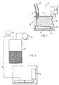
- FIG. 1 a schematic side view of an ink jet printhead of the type employed with the present invention is shown in Fig. 1.
- the printhead generally designated 10, includes a resonator assembly 12 having an ink manifold and orifice plate (not shown) for generating filaments of ink 14.
- the resonator stimulates the filaments to break off into droplets in the region of charging electrodes 16 on a catcher assembly generally designated 18.
- Drops of ink are selectively charged by the charging electrodes and deflected onto a catcher face 20 and into a catcher throat 22. Uncharged drops proceed undeflected to a print medium (not shown). Collected ink is withdrawn through a catcher tube 24 and is recirculated.
- a catcher vacuum port 26 returns unprinted ink to the fluid system.
- the vacuum port comprises catcher face 20, a radius, and catcher throat 22.
- the catcher face 20 receives selectively charged drops of ink and the catcher radius directs the flow of selectively charged drops of ink from the catcher face into the catcher throat.
- the unprinted drops from the array of ink jets impact on the face 20 of the catcher, creating a film of ink attached to the face. Due to momentum from the impacting drops, the ink film flows toward the radius. The film remains attached to the catcher even as it flows around the radius and along the surface toward the throat opening.
- the catcher throat 22 accepts the flow of selectively charged drops of ink from the catcher face. In the throat, air is ingested along with the ink and, depending upon the vacuum level in the ink tank, either slug flow or bubble flow is established downstream of the throat.
- the throat 22 comprises a short, narrow gap 34 with a sudden enlargement 36, downstream of the gap, and converging-diverging passages, all of which together govern the ingested airflow.
- the flow continues to the catcher tube 24 where it is pulled away through an attached catcher return line 25.
- the flow characteristics of the catcher return line are different for the two optional lengths of twelve feet and twenty-four feet.
- the flow characteristics of the catcher vacuum port vary from catcher to catcher.
- the fluid characteristics vary from one ink type to another.
- a fixed vacuum level may be too high or too low in relation to the threshold level for bubble flow for a particular printer, due to the printer to printer variations. For example, if the level is too high, bubble flow will not be established, and the benefits of bubble flow will not be realized. Conversely, of the level is too low, although bubble flow is established, the ink will not be removed from the printhead fast enough. An ink spill and damage to the printhead may occur as a result.
- the ideal vacuum setting is the vacuum at which bubble flow is first established as the tank vacuum is lowered. This is the highest vacuum at which bubble flow can be established. Then there is no danger of the vacuum being too low to return ink from the printhead.
- a sudden decrease in pressure fluctuations in the catcher return fluid is used to detect the establishment of bubble flow in the catcher vacuum port and the catcher return line.
- a pressure transducer 28 in the catcher return line 25 near ink tank 30 end is used to monitor pressure fluctuations in the catcher return fluid.
- an initially high vacuum level in the tank established by vacuum pump 32, establishes slug flow, in which frothy slugs of ink travel at a much higher rate than the average liquid velocity, in the catcher vacuum port and the catcher return line.
- Very wide swings in pressure are associated with slug flow as the frothy slugs and liquid alternately travel past the pressure transducer.
- the tank vacuum is lowered automatically to a preset value, depending upon the catcher line length, that is still well above the bubble flow transition point for that length.
- the tank vacuum is then lowered from this point, preferably in pressure steps of 127mm (five inches) of water.
- the flow is allowed to stabilize and the pressure transducer monitored for indications of pressure fluctuations. If large pressure fluctuations are detected, the tank vacuum is lowered to the next step. This continues until the pressure fluctuations are reduced to a predetermined acceptable level.
- the slug flow suddenly transitions into the bubble flow regime.
- the ingested airflow is in the form of individual separate bubbles, rather than frothy slugs,which are entrained in the liquid phase and travel at the velocity of the liquid.
- bubble flow provides significantly reduced airflow and much less agitation than slug flow.
- the entrained bubbles traveling along with the liquid produce only small pressure fluctuations at the pressure transducer, which is being monitored for indications of large pressure fluctuations.
- the sudden decrease in pressure fluctuations is interpreted by the fluid system control software as the establishment of bubble flow.
- the tank vacuum level is then increased an incremental amount, depending upon the catcher line length, to the operating point.
- This incremental increase provides an increased margin above the minimum acceptable vacuum level.
- the incremental increase is possible without reverting back to slug flow because of a hysteresis pattern in the flow characteristics for the catcher return system.
- the tank vacuum level at which transition between bubble flow and slug flow occurs depends upon the direction of change of the tank vacuum. For decreasing tank vacuum, the transition of slug flow to bubble flow occurs at a lower vacuum level; whereas for increasing tank vacuum, the transition from bubble flow to slug flow occurs at a higher vacuum level. Thus, once bubble flow is established, the vacuum level can be increased somewhat without reverting back to slug flow.
- the present invention is useful in the field of ink jet printing, and has the advantage of providing a fluid flow detection system and method for detecting the fluid flow regime in the catcher vacuum port and catcher return line to the ink tank.
Landscapes
- Ink Jet (AREA)
- Particle Formation And Scattering Control In Inkjet Printers (AREA)
Claims (8)
- Fluidflusserfassungsverfahren zum Erkennen des Fluidfließverhaltens in einer Vakuumöffnung (26) einer Auffangeinrichtung und in einer Rückführleitung (25) einer Auffangeinrichtung zu einem Tintenbehälter (30) eines kontinuierlichen Tintenstrahldruckers zur Erzeugung einer Reihe paralleler, selektiv aufgeladener Tropfenstrahlen aus einem Fluidsystem, wobei das Verfahren die folgenden Schritte beinhaltet:
Bereitstellen einer Auffangeinrichtung (18) mit schwacher Luftströmung zur Erzielung eines Blasenflusses in der Vakuumöffnung der Auffangeinrichtung und in der Rückführleitung (25) der Auffangeinrichtung, wobei die Rückführleitung der Auffangeinrichtung den Rückfluss aus der Auffangeinrichtung enthält,
gekennzeichnet durchErzeugen eines hohen Ausgangsvakuums im Tintenbehälter (30), um im Rückstrom aus der Auffangeinrichtung einen Schwallfluss hervorzurufen;Überwachen der Druckschwankungen im Rückfluss der Auffangeinrichtung zum Tintenbehälter (30);automatisches Absenken des Vakuums im Tintenbehälter (30) auf einen voreingestellten Wert oberhalb des Übergangspunkts zum Blasenfluss;schrittweises Absenken des Behältervakuums ausgehend von dem voreingestellten Pegel, während die Stärke der Druckschwankungen überwacht wird;Konstanthalten des Pegels des Behältervakuums, wenn die Stärke der Druckschwankungen durch Eintritt des Blasenflusses unter einen vorgegebenen Pegel abgefallen ist;Erhöhen des Behältervakuums um einen vorgegebenen Schritt und Beibehaltung dieses Behältervakuums als Arbeitspunkt für den Blasenfluss im Drucker. - Fluidflusserfassungsverfahren nach Anspruch 1,
bei dem die Vakuumöffnung (26) der Auffangeinrichtung aufweist:eine Auffangfläche (20),einen Auffangradius undeinen Auffangschlund (22). - Fluidflusserfassungsverfahren nach Anspruch 2,bei dem der Auffangschlund (22) einen kurzen, engen Spalt (34) mit einer plötzlichen Erweiterung (36) stromabwärts des Spalts sowie zusammenlaufende undauseinanderlaufende Kanäle aufweist, um den aufgenommenen Luftstrom zu steuern.
- Fluidflusserfassungsverfahren nach Anspruch 2 oder 3,
bei dem die Vakuumöffnung (26) der Auffangeinrichtung nicht für den Druck verwendete Tinte in das Fluidsystem zurückführt. - Tintenstrahldrucker zur Erzeugung einer Reihe paralleler, selektiv aufgeladener Tropfenstrahlen aus einem Fluidsystem, umfassend:gekennzeichnet durcheine Vakuumöffnung (26) einer Auffangeinrichtung und eine Rückführleitung (25) der Auffangeinrichtung zu einem Tintenbehälter (30);eine Auffangeinrichtung (18) mit schwachem Luftstrom zur Erzielung eines Blasenflusses in der Vakuumöffnung der Auffangeinrichtung und in der Rückführleitung (25) der Auffangeinrichtung, wobei die Rückführleitung der Auffangeinrichtung den Rückstrom aus der Auffangeinrichtung enthält,Mittel zum Erzeugen eines hohen Ausgangsvakuums im Tintenbehälter (30), um einen Schwallfluss im Rückstrom aus der Auffangeinrichtung zu erzeugen;Mittel zum Überwachen von Druckschwankungen im Rückstrom aus der Auffangeinrichtung zum Tintenbehälter (30);Mittel zum automatischen Absenken des Vakuums im Tintenbehälter (30) auf einen voreingestellten Wert oberhalb des Übergangspunkts zum Blasenfluss;Mittel zum schrittweisen Absenken des Behältervakuums unter den voreingestellten Pegel, während die Stärke der Druckschwankungen überwacht wird;Mittel zur Konstanthaltung des Behältervakuumpegels, wenn die Stärke der Druckschwankungen durch Eintritt des Blasenflusses unter einen vorgegebenen Wert abgefallen ist; undMittel zur Erhöhung des Behältervakuums um einen vorgegebenen Schritt und zur Beibehaltung dieses Behältervakuums als Arbeitspunkt für den Blasenfluss im Drucker.
- Tintenstrahldrucker nach Anspruch 5,
bei dem die Vakuumöffnung (26) der Auffangeinrichtung eine Auffangfläche (20), einen Auffangradius und einen Auffangschlund (22) aufweist. - Tintenstrahldrucker nach Anspruch 6,
bei dem der Auffangschlund (22) einen kurzen, engen Kanal (34) mit einer plötzlichen Erweiterung (36) stromabwärts des Kanals sowie zusammenlaufende und auseinanderlaufende Kanäle zur Steuerung des aufgenommenen Luftstroms aufweist. - Tintenstrahldrucker nach Anspruch 6 oder 7,
bei dem die Vakuumöffnung (26) der Auffangeinrichtung nicht für den Druck verwendete Tinte in das Fluidsystem zurückführt.
Applications Claiming Priority (2)
| Application Number | Priority Date | Filing Date | Title |
|---|---|---|---|
| US640103 | 1996-04-30 | ||
| US08/640,103 US5739829A (en) | 1996-04-30 | 1996-04-30 | Bubble flow detection |
Publications (3)
| Publication Number | Publication Date |
|---|---|
| EP0805040A2 EP0805040A2 (de) | 1997-11-05 |
| EP0805040A3 EP0805040A3 (de) | 1998-06-24 |
| EP0805040B1 true EP0805040B1 (de) | 2001-11-07 |
Family
ID=24566858
Family Applications (1)
| Application Number | Title | Priority Date | Filing Date |
|---|---|---|---|
| EP97302697A Expired - Lifetime EP0805040B1 (de) | 1996-04-30 | 1997-04-21 | Erfassung des Tröpfchendurchflusses |
Country Status (6)
| Country | Link |
|---|---|
| US (1) | US5739829A (de) |
| EP (1) | EP0805040B1 (de) |
| JP (1) | JPH1034975A (de) |
| AU (1) | AU714215B2 (de) |
| CA (1) | CA2203956A1 (de) |
| DE (1) | DE69707965T2 (de) |
Families Citing this family (7)
| Publication number | Priority date | Publication date | Assignee | Title |
|---|---|---|---|---|
| US6444019B1 (en) | 1998-11-06 | 2002-09-03 | Videojet Technologies Inc. | Ink jet ink composition |
| US6726756B1 (en) | 2000-05-26 | 2004-04-27 | Videojet Technologies Inc. | Continuous ink jet printing ink composition |
| FR2825650B1 (fr) | 2001-06-12 | 2004-04-30 | Imaje Sa | Dispositif et procede de recuperation de jets de liquide |
| US6962411B2 (en) * | 2003-01-02 | 2005-11-08 | Eastman Kodak Company | Anti-wicking catcher arrangement for a solvent ink printhead |
| GB2455775B (en) | 2007-12-21 | 2012-07-18 | Linx Printing Tech | Inkjet printer and flow restriction system therefor |
| GB2566628B (en) * | 2016-05-13 | 2021-01-06 | Domino Uk Ltd | Improvements in or relating to continuous inkjet printers |
| GB2550210B (en) | 2016-05-13 | 2019-01-23 | Domino Uk Ltd | Improvements in or relating to continuous inkjet printers |
Family Cites Families (12)
| Publication number | Priority date | Publication date | Assignee | Title |
|---|---|---|---|---|
| US3836914A (en) * | 1972-12-20 | 1974-09-17 | Mead Corp | Catcher for a jet drop recorder |
| JPS54136329A (en) * | 1978-04-14 | 1979-10-23 | Hitachi Ltd | Ink circulating device of ink jet device |
| JPS6119369A (ja) * | 1984-07-06 | 1986-01-28 | Oki Electric Ind Co Ltd | 荷電制御型インクジエツト記録装置 |
| US4639738A (en) * | 1985-04-12 | 1987-01-27 | Eastman Kodak Company | Ink level detection system for ink jet printing apparatus |
| US4622562A (en) * | 1985-04-12 | 1986-11-11 | Eastman Kodak Company | Ink jet printhead multi-component heating |
| US4839664A (en) * | 1987-07-02 | 1989-06-13 | Burlington Industries, Inc. | Fluid-jet catcher with removable porous metal ingestion blade |
| US4811035A (en) * | 1988-03-14 | 1989-03-07 | Eastman Kodak Company | Modular two-color fluid system for continuous ink jet printer |
| US4837585A (en) * | 1988-04-25 | 1989-06-06 | Eastman Kodak Company | Continuous ink jet printer having improved system for reducing pressure variations |
| US4929966A (en) * | 1989-01-03 | 1990-05-29 | Eastman Kodak Company | Continuous ink jet printer with a gravity drain, catcher return system |
| US5469202A (en) * | 1992-03-20 | 1995-11-21 | Scitex Digital Printing, Inc. | Continuous ink jet catcher with improved screen structure |
| FR2690648B1 (fr) * | 1992-04-30 | 1994-07-08 | Imaje | Methode d'optimisation du fonctionnement d'une imprimante a jet d'encre et imprimante utilisant une telle methode. |
| US5394177A (en) * | 1992-05-29 | 1995-02-28 | Scitex Digital Printing, Inc. | Four inch fluid system |
-
1996
- 1996-04-30 US US08/640,103 patent/US5739829A/en not_active Expired - Fee Related
-
1997
- 1997-04-21 DE DE69707965T patent/DE69707965T2/de not_active Expired - Fee Related
- 1997-04-21 EP EP97302697A patent/EP0805040B1/de not_active Expired - Lifetime
- 1997-04-28 JP JP9111057A patent/JPH1034975A/ja active Pending
- 1997-04-29 CA CA002203956A patent/CA2203956A1/en not_active Abandoned
- 1997-04-30 AU AU19941/97A patent/AU714215B2/en not_active Ceased
Also Published As
| Publication number | Publication date |
|---|---|
| US5739829A (en) | 1998-04-14 |
| AU714215B2 (en) | 1999-12-23 |
| DE69707965D1 (de) | 2001-12-13 |
| JPH1034975A (ja) | 1998-02-10 |
| CA2203956A1 (en) | 1997-10-30 |
| DE69707965T2 (de) | 2002-06-27 |
| EP0805040A3 (de) | 1998-06-24 |
| EP0805040A2 (de) | 1997-11-05 |
| AU1994197A (en) | 1997-11-06 |
Similar Documents
| Publication | Publication Date | Title |
|---|---|---|
| EP1108542B1 (de) | Kontinuierlich arbeitendes Tintenstrahlsystem mit nicht kreisförmigen Öffnungen | |
| US6505921B2 (en) | Ink jet apparatus having amplified asymmetric heating drop deflection | |
| US4190844A (en) | Ink-jet printer with pneumatic deflector | |
| JP2002508714A (ja) | 高粘度流体のマルチジェット流発生用の装置及び方法 | |
| JP2009006727A (ja) | イメージ印刷する装置及びインク液滴を分ける方法 | |
| US20130278682A1 (en) | Continuous inkjet printing system and method for producing selective deflection of droplets formed from two different break off lengths | |
| EP0561205B1 (de) | Auffangvorrichtung für kontinuierlichen Tintenstrahl mit Schirmstruktur | |
| CN101277819B (zh) | 通过不同的油墨喷射流偏转的印刷方法和装置 | |
| JP5133691B2 (ja) | 非導電性流体液滴の特定用装置及び方法 | |
| EP0805040B1 (de) | Erfassung des Tröpfchendurchflusses | |
| US4612553A (en) | Method for operational status checks of an ink jet printer | |
| EP1112847B1 (de) | Kontinuierlicher Tintenstrahldrucker mit einem Kerbendeflektor | |
| EP1221373B1 (de) | Mechanismus und Verfahren zum Vergrössern des Ablenkungswinkels von Tintentropfen | |
| US8382258B2 (en) | Moving liquid curtain catcher | |
| US4171527A (en) | Ink jet contamination detecting system | |
| US7938517B2 (en) | Jet directionality control using printhead delivery channel | |
| US8091992B2 (en) | Deflection device including gas flow restriction device | |
| EP0043295B1 (de) | Flüssigkeitströpfchenaufzeichnungsvorrichtung | |
| EP0805039B1 (de) | Tintenauffangvorrichtung mit geringem Luftstrom für kontinuierlich arbeitenden Tintenstrahldrucker | |
| US8857954B2 (en) | Printhead including coanda catcher with grooved radius | |
| US20100277522A1 (en) | Printhead configuration to control jet directionality | |
| JPH0948125A (ja) | インクジェット記録装置の記録ヘッド、該記録ヘッドを用いたインクジェット記録装置および該記録ヘッドの記録方法 | |
| US8746863B1 (en) | Printhead including coanda catcher with grooved radius | |
| US8740366B1 (en) | Printhead including coanda catcher with grooved radius | |
| JPH02500659A (ja) | 液体流偏向印刷方法および装置 |
Legal Events
| Date | Code | Title | Description |
|---|---|---|---|
| PUAI | Public reference made under article 153(3) epc to a published international application that has entered the european phase |
Free format text: ORIGINAL CODE: 0009012 |
|
| AK | Designated contracting states |
Kind code of ref document: A2 Designated state(s): DE FR GB |
|
| PUAL | Search report despatched |
Free format text: ORIGINAL CODE: 0009013 |
|
| AK | Designated contracting states |
Kind code of ref document: A3 Designated state(s): DE FR GB |
|
| 17P | Request for examination filed |
Effective date: 19980807 |
|
| 17Q | First examination report despatched |
Effective date: 19990722 |
|
| GRAG | Despatch of communication of intention to grant |
Free format text: ORIGINAL CODE: EPIDOS AGRA |
|
| GRAG | Despatch of communication of intention to grant |
Free format text: ORIGINAL CODE: EPIDOS AGRA |
|
| GRAH | Despatch of communication of intention to grant a patent |
Free format text: ORIGINAL CODE: EPIDOS IGRA |
|
| GRAH | Despatch of communication of intention to grant a patent |
Free format text: ORIGINAL CODE: EPIDOS IGRA |
|
| GRAA | (expected) grant |
Free format text: ORIGINAL CODE: 0009210 |
|
| AK | Designated contracting states |
Kind code of ref document: B1 Designated state(s): DE FR GB |
|
| REF | Corresponds to: |
Ref document number: 69707965 Country of ref document: DE Date of ref document: 20011213 |
|
| REG | Reference to a national code |
Ref country code: GB Ref legal event code: IF02 |
|
| PLBE | No opposition filed within time limit |
Free format text: ORIGINAL CODE: 0009261 |
|
| STAA | Information on the status of an ep patent application or granted ep patent |
Free format text: STATUS: NO OPPOSITION FILED WITHIN TIME LIMIT |
|
| 26N | No opposition filed | ||
| REG | Reference to a national code |
Ref country code: GB Ref legal event code: 732E |
|
| REG | Reference to a national code |
Ref country code: FR Ref legal event code: TP |
|
| PGFP | Annual fee paid to national office [announced via postgrant information from national office to epo] |
Ref country code: GB Payment date: 20050314 Year of fee payment: 9 |
|
| PGFP | Annual fee paid to national office [announced via postgrant information from national office to epo] |
Ref country code: FR Payment date: 20050401 Year of fee payment: 9 |
|
| PGFP | Annual fee paid to national office [announced via postgrant information from national office to epo] |
Ref country code: DE Payment date: 20050429 Year of fee payment: 9 |
|
| PG25 | Lapsed in a contracting state [announced via postgrant information from national office to epo] |
Ref country code: GB Free format text: LAPSE BECAUSE OF NON-PAYMENT OF DUE FEES Effective date: 20060421 |
|
| PG25 | Lapsed in a contracting state [announced via postgrant information from national office to epo] |
Ref country code: DE Free format text: LAPSE BECAUSE OF NON-PAYMENT OF DUE FEES Effective date: 20061101 |
|
| GBPC | Gb: european patent ceased through non-payment of renewal fee |
Effective date: 20060421 |
|
| REG | Reference to a national code |
Ref country code: FR Ref legal event code: ST Effective date: 20061230 |
|
| PG25 | Lapsed in a contracting state [announced via postgrant information from national office to epo] |
Ref country code: FR Free format text: LAPSE BECAUSE OF NON-PAYMENT OF DUE FEES Effective date: 20060502 |