EP0804957B1 - Befestigungskopf für Filter - Google Patents
Befestigungskopf für Filter Download PDFInfo
- Publication number
- EP0804957B1 EP0804957B1 EP97303030A EP97303030A EP0804957B1 EP 0804957 B1 EP0804957 B1 EP 0804957B1 EP 97303030 A EP97303030 A EP 97303030A EP 97303030 A EP97303030 A EP 97303030A EP 0804957 B1 EP0804957 B1 EP 0804957B1
- Authority
- EP
- European Patent Office
- Prior art keywords
- chamber
- fuel
- filter
- ports
- flow
- Prior art date
- Legal status (The legal status is an assumption and is not a legal conclusion. Google has not performed a legal analysis and makes no representation as to the accuracy of the status listed.)
- Expired - Lifetime
Links
- 238000004891 communication Methods 0.000 claims description 38
- 238000005553 drilling Methods 0.000 claims description 28
- 239000000446 fuel Substances 0.000 description 104
- 238000005192 partition Methods 0.000 description 10
- 230000037452 priming Effects 0.000 description 6
- 238000000034 method Methods 0.000 description 4
- 238000005266 casting Methods 0.000 description 3
- 230000000994 depressogenic effect Effects 0.000 description 3
- 238000007789 sealing Methods 0.000 description 3
- 230000001419 dependent effect Effects 0.000 description 2
- 239000000463 material Substances 0.000 description 2
- 230000004048 modification Effects 0.000 description 2
- 238000012986 modification Methods 0.000 description 2
- 241000272525 Anas platyrhynchos Species 0.000 description 1
- 239000000356 contaminant Substances 0.000 description 1
- 239000002283 diesel fuel Substances 0.000 description 1
- 239000002828 fuel tank Substances 0.000 description 1
- 238000004519 manufacturing process Methods 0.000 description 1
- 238000000465 moulding Methods 0.000 description 1
- 238000005086 pumping Methods 0.000 description 1
Images


Classifications
-
- B—PERFORMING OPERATIONS; TRANSPORTING
- B01—PHYSICAL OR CHEMICAL PROCESSES OR APPARATUS IN GENERAL
- B01D—SEPARATION
- B01D27/00—Cartridge filters of the throw-away type
- B01D27/08—Construction of the casing
-
- B—PERFORMING OPERATIONS; TRANSPORTING
- B01—PHYSICAL OR CHEMICAL PROCESSES OR APPARATUS IN GENERAL
- B01D—SEPARATION
- B01D35/00—Filtering devices having features not specifically covered by groups B01D24/00 - B01D33/00, or for applications not specifically covered by groups B01D24/00 - B01D33/00; Auxiliary devices for filtration; Filter housing constructions
- B01D35/26—Filters with built-in pumps filters provided with a pump mounted in or on the casing
-
- B—PERFORMING OPERATIONS; TRANSPORTING
- B01—PHYSICAL OR CHEMICAL PROCESSES OR APPARATUS IN GENERAL
- B01D—SEPARATION
- B01D35/00—Filtering devices having features not specifically covered by groups B01D24/00 - B01D33/00, or for applications not specifically covered by groups B01D24/00 - B01D33/00; Auxiliary devices for filtration; Filter housing constructions
- B01D35/30—Filter housing constructions
- B01D35/301—Constructions of two or more housings
- B01D35/303—Constructions of two or more housings the housings being modular, e.g. standardised
Definitions
- This invention relates to a filter head for use with a filter cartridge of the type including a filter medium located within a housing, a surface of the housing being provided with apertures to permit access to one side of the filter material.
- the housing is provided with a through passage communicating with the other side of the filter material.
- the filter head sealingly engages the cartridge, in use, the head having an inlet port and an outlet port which communicate with the apertured surface and passage of the cartridge.
- the head may also include other ports, and possibly a priming arrangement for priming the filter.
- a variety of different filter heads are required.
- US 5354464 describes a filter head for use with a filter cartridge in which regions of the filter head are provided with openings to permit communication between inlet and outlet ports and chambers of the filter head so as to provide a number of different flow paths through the filter head.
- FR 2010086 discloses a filter head which provides only a single flow path for fuel through the filter head. The filter head in FR 2010086 is therefore only suitable for use in a limited number of applications.
- a filter head for use with a filter cartridge, the filter head comprising a plurality of ports, a first chamber and a second chamber, the second chamber being arranged to communicate with an axially extending passage of the filter cartridge, the filter head comprising means in a region located beneath the first chamber which is adaptable to permit selective communication between the first chamber and the surface of the cartridge, selective communication between at least one of the ports and the first chamber, and selective communication between at least one of the ports and the second chamber.
- the filter head may further comprise means for permitting selective communication between the first chamber and the second chamber.
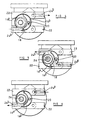
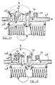
- the filter head illustrated in Figures 1 and 9 comprises a generally circular cover 10 having a recess in the lower surface thereof arranged to receive the upper, apertured end surface of a filter cartridge of the type described hereinbefore.
- the cover 10 is provided with a downwardly extending hollow tubular projection 12 which is intended to communicate, in use, with the through passage of the filter cartridge, suitable seals being provided to seal the projection 12 to the through passage of the cartridge.
- the cover 10 is provided with an upstanding mounting bracket 14 which is used to support the filter head, and hence to support the filter cartridge. It will be understood that other mounting techniques may be used in which the bracket 14 is otherwise oriented or omitted.
- the upper surface of the cover 10 is shaped to define a chamber 16 of substantially cylindrical form and, as shown in Figure 1, the chamber 16 is not coaxial with the cover 10.
- the chamber 16 is provided with a dividing wall 18 which is integral with the cover 10, a gasket or blanking piece which may form part of a cap being receivable within the chamber 16 and cooperable with the wall 18 to close the chamber 16 and divide the chamber 16 into first and second sub-chambers 16 a , 16 b .
- the cap may include the actuator of a hand primer.
- the part of the cover 10 defining part of the second sub-chamber 16 b is provided with an aperture 20 which communicates with the interior of the projection 12.
- the second sub-chamber 16 b communicates with the through passage of the filter cartridge.
- a pair of parallel ribs 22 which are positioned such that if axially extending bores were provided in the ribs 22, the bores would extend through the chamber 16.
- the ends of the ribs 22 are pre-drilled to define ports 24, although in the arrangement illustrated in Figure 1, the ports 24 do not communicate with the chamber 16.
- the upper face of each of the ribs 22 is also drilled to form a further pair of ports 24.
- the first sub-chamber 16 a is shaped so as to define supporting means 25 suitable for receiving a primer, for example of the type described with reference to Figures 16 a , 16 b and 16 c .
- the filter head illustrated in Figure 1 is not suitable for use with a filter cartridge as none of the ports 24 communicate with the second sub-chamber 16 b , thus fuel is not permitted to flow to or from the through passage of the filter cartridge, and similarly fuel is not permitted to flow to or from the upper, apertured surface of the filter cartridge.
- the filter head requires modification to permit communication between at least one of the ports 24 and the second sub-chamber 16 b , and further communication between another of the ports 24 and the upper surface of the cartridge.
- the selection of which of the ports 24 to connect to the second sub-chamber 16 b , and which of the ports 24 to be arranged to communicate with the upper surface of the filter cartridge depends upon the intended use of the filter. A non-exhaustive range of possibilities are illustrated in Figures 2 to 8.
- a first port 24a is drilled to communicate with the first sub-chamber 16a, and an aperture 26 is formed in the surface of the cover 10 defining part of the first chamber 16 a thus permitting fuel to flow from a suitable source of fuel to the upper surface of a filter cartridge connected to the filter head.
- a second port 24 b is drilled so as to communicate with the second sub-chamber 16 b and thus communicate with the through passage of the filter cartridge. In use, fuel from a fuel source or reservoir is supplied through the first port 24 a and the first sub-chamber 16 a to the upper surface of the filter cartridge.
- the fuel flows downwardly through the filter cartridge, through the filter medium, the filtered fuel being returned through the central, through passage to the projection 12 and through the second sub-chamber 16 b to the second port 24 b .
- the fuel flows to a fuel pump for subsequent supply at high pressure to an engine.
- Fuel flow in this direction through the filter cartridge is referred to as agglomerator flow.
- a primer for example of the type described with reference to Figures 16 a , 16 b and 16 c may be supported by the supporting means 25 in the first sub-chamber 16 a .
- the port 24 a is formed in a different one of the ribs 22 to the second port 24 b , it will be recognised that these ports could be provided in a single one of the ribs 22, either of the ports 24 which can be arranged to communicate with the first sub-chamber 16 a be suitable for connection to the fuel supply, and any of the ports which can be connected to the second sub-chamber 16 b being suitable for use for connection to the fuel pump.
- FIG. 3 The arrangement illustrated in Figure 3 is similar to that of Figure 2 in that a first port 24 a is drilled so as to communicate with the first sub-chamber 16 a which, as in the embodiment illustrated in Figure 2, is provided with an aperture 26 whereby the first sub-chamber 16 a communicates with the upper surface of the filter cartridge. Also as in the embodiment illustrated in Figure 2, a second port 24 b is drilled so as to communicate with the second sub-chamber 16 b , in this case the second port 24 b and first port 24 a being provided in the same one of the ribs 22.
- the flow path of fuel from the source to the fuel pump is therefore similar to that of one of the variants to the embodiment illustrated in Figure 2.
- FIG. 3 differs from that of Figure 2 in that fuel which is not supplied by the pump to an associated engine is returned to a third port 24 c which is drilled so as to communicate with a fourth port 24 d (one of the ports 24 provided in the upper face of the ribs 22), the third and fourth ports 24 c , 24 d communicating through an aperture in the cover 10 with the upper face of the filter cartridge.
- the fuel returned from the fuel pump is therefore returned to the dirty side of the filter cartridge.
- the fourth port 24 d is connected to an auxiliary device for example in the form of an auxiliary fuel reservoir.
- a small aperture 28 is provided in the cover 10 in order to bleed air from the upper surface of the filter cartridge into the first sub-chamber 16 a , excess fuel also escaping through this aperture.
- a fifth port 24 e is connected to the first sub-chamber 16 a and is arranged to return excess fuel and air from the filter head to the fuel supply reservoir. This arrangement is intended for use where a separate fuel supply pump is used to supply fuel to the filter. By selecting appropriate relative diameters for the first and fifth ports 24 a , 24 e , the fuel supply pressure to the filter can be maintained at a suitable level.
- Figure 3 omits to show the support means 25 for the primer, but it will be recognised that such support means could be provided, and hence that a primer for example of the type described with reference to any one of Figures 11 to 16 could be used in this embodiment.
- a first port 24 a is drilled so as to communicate with the first sub-chamber 16 a , the gasket or blanking piece which, with the wall 18, separates the first and second sub-chamber 16 a , 16 b is absent in order to permit fuel to flow from the first sub-chamber 16 a to the second sub-chamber 16 b and from there through the passage 20 to the through passage of the filter cartridge.
- the fuel then flows upwardly through the filter medium exiting at the upper surface of the filter cartridge.
- the aperture 26 is not drilled in this embodiment and hence fuel does not flow from the upper surface of the filter cartridge into the sub-chamber 16 a .
- a passage is drilled vertically into one of the ribs 22, and a second port 24 b provided in that rib 22 is drilled so as to communicate with the vertical drilling.
- the second port 24 b therefore communicates with the upper face of the filter cartridge.
- FIG. 5 The arrangement illustrated in Figure 5 is intended for use where filter flow is required and where fuel is required to be supplied from the right hand side of the filter to the left hand side in the orientation illustrated in Figure 5.
- a first port 24 a is drilled so as to communicate with the second sub-chamber 16 b and hence with the central through passage of the filter cartridge.
- the aperture 26 is provided in the cover 10, thus the first sub-chamber 16 a communicates with the upper surface of the filter cartridge, and a second port 24 b is drilled so as to communicate with the first sub-chamber 16 a whereby fuel is supplied to a fuel pump.
- the first sub-chamber 16 a is provided with support means 25 for a suitable hand primer.
- Figure 6 also illustrates an embodiment in which fuel is required to flow from the right-hand side of the filter assembly to the left-hand side.
- This embodiment is intended to achieve agglomerator flow, a first, inlet port 24 a being drilled so as to communicate with a vertical drilling in the cover 10 which communicates with the upper surface of the filter cartridge.
- Fuel from a suitable reservoir flows through the inlet port 24 a to the upper surface of the filter cartridge, and flows through the filter cartridge exiting along the through passage thereof which communicates through the aperture 20 with the second sub-chamber 16 b .
- the gasket or blanking piece is absent so as to permit communication between the first and second sub-chambers 16 a , 16 b , a second port 24 b being drilled so as to communicate with the first sub-chamber 16 a .
- the aperture 26 is not drilled thus direct communication between the first sub-chamber 16 a and the upper surface of the filter cartridge is not permitted.
- Figure 7 illustrates a modification in which both the inlet and the outlet are connected to the left-hand side of the filter assembly.
- a first port 24 a is drilled so as to communicate with the first sub-chamber 16 a , the gasket or blanking piece being absent so as to permit communication between the first and second sub-chambers 16 a , 16 b thus fuel from the first port 24 a is permitted to flow to the aperture 20 and from there to the central through passage of the filter cartridge.
- the fuel flows through the through passage of the filter cartridge and upwardly through the filter medium to the upper surface of the filter cartridge.
- a second port 24 b is drilled so as to communicate with a vertical drilling provided in the cover 10 which is located so as to communicate with the upper surface of the filter cartridge. Filter flow through the filter assembly is therefore achieved. It will be recognised that by reversing the connections to the first and second ports 24 a , 24 b agglomerator flow may be achieved.
- Figure 8 illustrates an arrangement where both the inlet and the outlet are connected to the right-hand side of the filter assembly.
- a first, inlet port 24 a is drilled so as to communicate with a vertically extending passage which communicates with the upper surface of the filter cartridge.
- a second, outlet port 24 b is drilled so as to communicate with the second sub-chamber 16 b , and hence to communicate with the through passage of the filter cartridge.
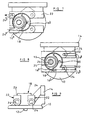
- FIG. 10 and 27 differs from that of Figure 1 in that a generally cylindrical insert 38 is provided within the chamber 16 the insert 38 being provided with an integral dividing wall 40.
- the insert 38 is arranged to carry a primer arrangement.
- Figure 10 illustrates that the cover 10 is provided with two aperture locations 42 a , 42 b .
- aperture 42 a provides communication between a first sub-chamber 44 a and the upper surface of the filter cartridge whilst the aperture 42 b provides communication between a second chamber 44 b and the through passage of the filter cartridge.
- the primer arrangement no longer communicates with the chamber containing the aperture 42 b , and instead the primer arrangement communicates with the aperture 42 a . If this aperture is drilled, the primer communicates through this aperture with the upper surface of the filter cartridge. The use of such an insert and primer arrangement obviates the requirement to correctly orientate the valve arrangement.
- FIG. 10 and 27 is intended to be modified so as to include drillings communicating with the first and second sub-chambers 44 a , 44 b and to permit communication between the sub-chambers in a manner similar to that described with reference to the embodiment illustrated in Figure 1 and the arrangements illustrated in Figures 2 to 8.
- Any suitable technique may be used to secure the filter cartridge to the filter head, for example by using a rod extending through the central through passage of the filter arrangement and clamp means for clamping the filter cartridge to the filter head, or alternatively another technique for clamping the filter cartridge to the filter head.
- the primer arrangement illustrated in Figure 11 comprises a pair of check valves 50, 52 located in the first sub-chamber 16 a .
- the chamber 16 is closed by a rubber dome 54 which may be depressed to pressurize the fuel within the chamber 16.
- the second sub-chamber 16 b is separated from the first sub-chamber 16 a by a separate gasket or sealing member 56.
- valves 50, 52 are arranged such that when the rubber dome 54 is depressed, fuel is supplied through the valve 52 to the upper surface of the filter cartridge, fuel not being permitted to flow past the valve 50 in this direction. Upon releasing the rubber dome 54, fuel is drawn into the sub-chamber 16 a through the valve 50, the valve 52 preventing fuel flow from the cartridge to the sub-chamber 16 a .
- Figure 11 further illustrates that as an alternative to only drilling some of the ports 24, if desired some of the ports 24 may be closed using plugs 58.
- Figure 12 The arrangement illustrated in Figure 12 is similar to that of Figure 11, but with the rubber dome 54 replaced by a plunger type actuator 60 for use in pumping fuel through the filter to prime the fuel system.
- Figures 11 and 12 show a separate gasket or sealing member 52 for separating the first and second sub-chambers 16 a , 16 b .
- the sub-chambers 16 a , 16 b may be separated from one another by part of the seal 62 used to seal the rubber dome 54, plunger type actuator 60 or other type of actuator to the cover 10.
- FIGs 14 and 15 illustrate an alternative arrangement in which the functions of the valves 50 and 52 are performed by a single valve member 64.
- the valve member 64 is a duck bill valve member having an enlarged head 64 a which, when orientated as in Figure 14, controls the supply of fuel from an inlet port 24 a to the first sub-chamber 16 a , and a central region 64 b arranged to control the supply of fuel to a cartridge, the valve member 64 permitting fuel to flow from the inlet port 24 a through the first sub-chamber 16 a to the cartridge, but preventing fuel from flowing in the reverse direction.
- the arrangement of Figure 14 therefore permits agglomerator flow.
- Filter flow may be achieved by modifying the arrangement of Figure 14 so that fuel from the cartridge is applied to the head 64 a , the fuel passing through the central region 64 b flowing to the outlet as shown in Figure 15.
- FIGs 16 a , 16 b and 16 c illustrate a valve assembly suitable for use in a hand primer which may be mounted in the first sub-chamber 16 a of the filter head illustrated in Figure 1.
- the valve assembly illustrated in Figure 16 a comprises a support member 30 which is of generally cylindrical form, a central region of the support 30 being substantially closed by a generally circular wall 32 the centre of which is open.
- a valve member 34 extends within the opening of the wall 32, the valve member 34 including an enlarged head 34 a which is arranged to prevent the valve member 34 passing completely through the central opening of the wall 32, and a duck-bill region 34 b which is arranged to open to permit flow of fuel therethrough in one direction and to substantially prevent the flow of fuel in an opposite direction.
- the head 34 a and support member 30 together define a chamber 30 a which communicates, in use, with an inlet or outlet part of the filter head.
- the direction in which fuel is permitted to flow is denoted by arrow A.
- Figure 16 b illustrates the valve assembly of Figure 16 a located in the chamber 16 of a filter head in which the direction of flow of fuel through the filter cartridge is such as to achieve agglomerator flow.
- an O-ring seal 36 is provided to seal the support member 30 to the support means located within the first sub-chamber 16a.
- actuation of a primer actuator for example in the form of a rubber dome, pumps fuel through the duck-bill region 34 b to the filter medium, release of the actuator drawing fuel from the inlet through the chamber 30 a and past the head 34 a which flexes to allow fuel flow from the chamber 30 a .
- Figure 16 c illustrates the valve assembly oriented so as to achieve filter flow. In this arrangement, the chamber 30 a communicates with a chamber 30 b which, in turn, communicates with an outlet of the filter head. Apertures 30 c are provided to allow fuel flow to the chamber 30 a .
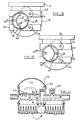
- the filter assembly illustrated in Figure 17 comprises a filter cartridge 110 which is secured to a filter head assembly 112.
- the filter cartridge 110 houses a filter member which is arranged to remove contaminants from a flow of diesel fuel therethrough.
- the flow of diesel through the filter member may be in a direction extending parallel to the axis of the filter cartridge 110, or alternatively may be in a radial direction.
- the upper surface of the filter cartridge includes apertures permitting fuel to enter or leave the cartridge
- the filter cartridge includes an axially extending passage whereby fuel can flow to or from the lower surface of the filter cartridge which is also apertured.
- the filter head assembly 112 must be able to permit communication with the axially extending passage and with the upper surface of the filter cartridge 110.
- the filter cartridge 110 includes an axially extending perforated passage, and an outer annular chamber.
- the filter head assembly 112 communicates with the axially extending passage and with an upper chamber defined, in part, by the upper surface of the filter cartridge 110, communication being permitted between the upper chamber and the outer annular chamber.
- the filter head assembly 112 described in greater detail hereinafter is suitable for use with both types of filter cartridge
- the filter head assembly 112 comprises a casting which includes an integral bracket 114 whereby the filter head assembly 112 and filter cartridge 110 secured thereto are mounted in position.
- the casting includes five ports 116, and means permitting an actuator 118 for a primer arrangement to be mounted thereon.
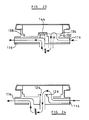
- Figure 18 illustrates the filter head assembly 112 in more detail, the bracket 114 and actuator 118 being omitted from this view.
- the filter head assembly 112 includes a generally cylindrical wall 120 with which the ports 116 are integral, the lower end of the cylindrical wall 120 being closed by a relatively thick, integral lower wall 122.
- the lower wall 122 is aligned with the ports 116.
- a recess 124 is formed in the lower wall 122, and a wall 126 extends around the recess 124, the wall 126 extending above the upper surface of the lower wall 122.
- the lower surface of the recess 124 is provided with an opening 128 (see Figure 19) which communicates with the interior of a hollow downwardly extending projection (not shown) which, in use, communicates with the axially extending passage of the filter cartridge 110, a suitable seal, for example an O-ring, being provided in order to seal the downwardly extending projection to the axially extending passage of the filter cartridge 110.
- a suitable seal for example an O-ring, being provided in order to seal the downwardly extending projection to the axially extending passage of the filter cartridge 110.
- Further walls 130 are provided which connect the wall 126 surrounding the recess 124 with the cylindrical wall 120 thus defining a chamber 132.
- a step 134 is provided at the interconnection between the cylindrical wall 120 and the lower wall 122, the step 134 being of the same height as the wall 126 and further walls 130.
- a partition 136 may be provided within the cylindrical wall 120, the partition 136 being mounted upon the step 134, wall 126 and the further walls 130. It will be appreciated that the partition 136 separates the interior of the cylindrical wall 120 into four chambers, the four chambers being the chamber 132, a chamber defined by the recess 124, a chamber 138 as illustrated in Figure 19 and a chamber 140 located above the partition 136.
- the partition 136 is provided with a pair of one way valves 142 which, as illustrated in Figure 20, are arranged to permit flow in opposite directions such that one of the one way valves 142 permits fuel to flow from the chamber 138 to the chamber 140, the other of the one way valves 142 permitting fuel to flow from the chamber 140 to the chamber 132.
- the actuator 118 for the primer is provided, if the actuator 118 is depressed, the volume of the chamber 140 is reduced, thus increasing the pressure of the fuel in the chamber 140 resulting in fuel flowing through the one way valve 142 to the chamber 132. Subsequent release of the actuator 118 results in the actuator 118 returning to its original position, for example under the action of a spring, reducing the pressure within the chamber 140 resulting in fuel flowing to the chamber 140 through the one way valve 142 from the chamber 138.
- each of the ports 116 is located adjacent the lower wall 122, and as illustrated in Figure 20 if a drilling is provided coaxially with any one of the ports 116, the drilling will extend into the recess 124 thus permitting communication between that port 116 and the recess 124. Further, if a vertical drilling is provided which communicates with any one of the ports 116, the drilling will permit communication between that port 116 and the chamber 138. It will be appreciated, therefore, that any one of the ports 116 can be made to communicate with the recess 124, and any one of the ports 116 can be made to communicate with the chamber 138.
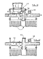
- Figure 22 illustrates how the filter head assembly 112 may be modified so as to be used where flow is required through the filter cartridge in the reverse direction to that shown in Figure 21, fuel flow in this direction being known as filter flow.
- one of the inlet ports 116 communicates through a vertically extending drilling with the chamber 138.
- a primer arrangement is provided whereby fuel can be supplied from the chamber 138 to the chamber 132.
- the vertically extending drilling from the chamber 132 to the upper surface of the filter cartridge 110 is not provided, and instead an opening is provided in the wall 126 whereby communication is permitted between the chamber 132 and the recess 124.
- fuel from the fuel source is supplied to the axially extending passage of the filter cartridge 110.
- a vertically extending drilling is provided in the underside of the filter head 112, this drilling communicating with one of the ports 116 whereby fuel from the clean side of the filter cartridge can flow from the upper surface of the filter cartridge 110 to one of the ports 116 and from there to a suitable pump.
- the opening may be omitted and instead the partition 136 may be modified so as to include a channel or recess providing a flow path between the chamber 132 and the recess 124.
- FIG. 23 The arrangement illustrated in Figure 23 is intended to achieve agglomerator flow through the filter cartridge 110 where priming is not required.
- the actuator 118 is omitted, and in addition the partition 136 containing the one way valves 142 is omitted.
- a sealing cap 144 is provided on the wall 126.
- the drillings necessary for the head 112 to be used in this way are the same as those shown in Figure 21, although it will be appreciated that the choice of ports 116 to be connected to the source of fuel and suitable pump is dependent upon the particular fuel system with which the filter head 112 is to be used.
- fuel flows to the filter head 112 through one of the ports 116, and through a vertically extending drilling into the chamber 138.
- the partition 136 is not present, the fuel is able to flow directly to the chamber 132 and from there to the upper surface of the filter cartridge 110. It will be appreciated that the further walls 130 may be omitted where the filter head 110 is to be used in this manner.
- the fuel flows through the cartridge from the upper surface thereof to the axially extending passage and is returned to the recess 124 through the opening 128, and from the recess 124 to the port 116 which communicates therewith.
- Figure 24 illustrates an arrangement in which filter flow is achieved where a primer is not required.
- the flow path through the filter head 112 is similar to that shown in Figure 22, but as priming is not required, and hence the partition 136 is not present, there is no need to provide the opening in the wall 126, fuel being able to flow directly from the chamber 138 to the recess 124 and from there to the axially extending passage of the filter cartridge 110, fuel escaping from the upper surface of the filter cartridge 110 through a vertically extending drilling provided in the lower surface of the filter head 112 as described with reference to Figure 22.
- return fuel may be supplied to any of the ports 116 not already in use to either the clean side or dirty side of the filter, and further any one of the ports 116 may be connected to provide a return fuel line to the fuel tank and to provide a vent whereby air may be removed from the filter head 112.
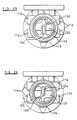
- FIG. 25 differs from that of Figures 17 to 24 in that the recess 124 is not located centrally within the chamber defined by the cylindrical wall 120, and instead is offset towards one side thereof. It will be appreciated that with the recess 124 so located, direct communication between the recess 124 and two of the ports 116 is not possible in the manner described hereinbefore, horizontal drilling of those ports not resulting in a direct connection between the recess 124 and those ports 116.
- the part of the lower wall 122 adjacent those ports 116 is vertically aligned with the base of the recess 124 thus reducing the thickness of the lower wall 122 which may result in a simplified moulding process.
- two of the ports 116 are not capable of direct communication with the recess 124, it will be appreciated that three of the ports are capable of connection to the recess 124 by providing horizontal drillings, and communication between four of the ports 116 and the chambers 132, 138 may be achieved by providing vertically extending drillings.
- Figure 26 illustrates an arrangement similar to that of Figure 25 but in which the recess 124 is located so as to permit direct communication between the recess 124 and the two ports 116 which are not capable of communication with the recess 124 in the arrangement illustrated in Figure 25.
- Manufacture of the embodiments illustrated in Figures 25 and 26 may be achieved using a single die having a core pin which is capable of being moved to permit casting of the filter head with the recess 124 in either of the position shown in Figure 25 or the position shown in Figure 26. It will be appreciated, therefore, that the tooling requirements necessary to provide filter heads capable of being used in a variety of different fuel flow paths are reduced.
Landscapes
- Chemical & Material Sciences (AREA)
- Chemical Kinetics & Catalysis (AREA)
- Separation Using Semi-Permeable Membranes (AREA)
- Fuel-Injection Apparatus (AREA)
- Feeding And Controlling Fuel (AREA)
- Treatment Of Water By Ion Exchange (AREA)
- Ink Jet (AREA)
- Filtration Of Liquid (AREA)
- Coating Apparatus (AREA)
Claims (6)
- Filterkopf zur Verwendung mit einer Filterpatrone, wobei der Filterkopf eine Vielzahl von Öffnungen (24; 116), eine erste Kammer (16a; 132) und eine zweite Kammer (16b) umfasst, wobei die zweite Kammer (16b) angeordnet ist, um mit einem sich axial erstreckenden Durchgang der Filterpatrone zu kommunizieren,
dadurch gekennzeichnet, dass der Filterkopf eine Einrichtung in einem unterhalb der ersten Kammer (16a; 132) angeordneten Bereich umfasst, die dafür ausgelegt ist, um eine selektive Kommunikation zwischen der ersten Kammer (16a; 132) und einer Oberfläche der Patrone, eine selektive Kommunikation zwischen wenigstens einer der Öffnungen (24; 116) und der ersten Kammer (16a; 132) und eine selektive Kommunikation zwischen wenigstens einer der Öffnungen (24; 116) und der zweiten Kammer zu ermöglichen. - Filterkopf nach Anspruch 1, ferner umfassend eine Einrichtung, um eine selektive Kommunikation zwischen der ersten Kammer (16a; 132) und der zweiten Kammer (16b) zu ermöglichen.
- Filterkopf nach Anspruch 1 oder Anspruch 2, wobei der Bereich mit einer Bohrung versehen ist, wo eine Kommunikation zwischen der ersten Kammer (16a; 132) und der zugehörigen Oberfläche der Patrone benötigt wird, wobei die Bohrung weggelassen wird, wo die Kommunikation nicht benötigt wird.
- Filterkopf nach einem der Ansprüche 1 bis 3, wobei der Bereich mit einer Bohrung versehen ist, wo eine Kommunikation zwischen wenigstens einer der Öffnungen (24; 116) und der ersten Kammer (16a; 132) benötigt wird, wobei die Bohrung weggelassen wird, wo eine Kommunikation nicht benötigt wird.
- Filterkopf nach einem der Ansprüche 1 bis 4, wobei der Bereich mit einer Bohrung versehen ist, wo eine Kommunikation zwischen wenigstens einer der Öffnungen (24; 116) und der zweiten Kammer benötigt wird, wobei die Bohrung weggelassen wird, wo eine Kommunikation nicht benötigt wird.
- Filterkopf nach einem der Ansprüche 1 bis 5, ferner umfassend eine Vorladeanordnung.
Applications Claiming Priority (4)
| Application Number | Priority Date | Filing Date | Title |
|---|---|---|---|
| GB9609385 | 1996-05-03 | ||
| GBGB9609385.1A GB9609385D0 (en) | 1996-05-03 | 1996-05-03 | Filter head |
| GBGB9620003.5A GB9620003D0 (en) | 1996-09-21 | 1996-09-21 | Filter head |
| GB9620003 | 1996-09-21 |
Publications (3)
| Publication Number | Publication Date |
|---|---|
| EP0804957A2 EP0804957A2 (de) | 1997-11-05 |
| EP0804957A3 EP0804957A3 (de) | 1998-02-11 |
| EP0804957B1 true EP0804957B1 (de) | 2002-01-16 |
Family
ID=26309270
Family Applications (1)
| Application Number | Title | Priority Date | Filing Date |
|---|---|---|---|
| EP97303030A Expired - Lifetime EP0804957B1 (de) | 1996-05-03 | 1997-05-02 | Befestigungskopf für Filter |
Country Status (3)
| Country | Link |
|---|---|
| EP (1) | EP0804957B1 (de) |
| DE (1) | DE69709567T2 (de) |
| ES (1) | ES2168579T3 (de) |
Families Citing this family (3)
| Publication number | Priority date | Publication date | Assignee | Title |
|---|---|---|---|---|
| US5985144A (en) * | 1997-07-03 | 1999-11-16 | Stanadyne Automotive Corp. | Reverse flow cartridge |
| GB2333245A (en) * | 1998-01-14 | 1999-07-21 | Lucas Ind Plc | Filter heads with variable flow paths |
| US20200094176A1 (en) * | 2018-09-21 | 2020-03-26 | Perkins Engines Company Limited | Fluid filter and priming pump assembly and methods |
Family Cites Families (3)
| Publication number | Priority date | Publication date | Assignee | Title |
|---|---|---|---|---|
| GB1270092A (en) * | 1968-06-04 | 1972-04-12 | Amf Inc | Improvements in or relating to fluid treatment apparatus |
| CA1190865A (en) * | 1982-02-24 | 1985-07-23 | Michael E. Wilson | Filter assembly |
| US5354464A (en) * | 1990-03-14 | 1994-10-11 | Water Factory Systems | Multi-port connecting device |
-
1997
- 1997-05-02 EP EP97303030A patent/EP0804957B1/de not_active Expired - Lifetime
- 1997-05-02 ES ES97303030T patent/ES2168579T3/es not_active Expired - Lifetime
- 1997-05-02 DE DE69709567T patent/DE69709567T2/de not_active Expired - Fee Related
Also Published As
| Publication number | Publication date |
|---|---|
| EP0804957A3 (de) | 1998-02-11 |
| DE69709567D1 (de) | 2002-02-21 |
| ES2168579T3 (es) | 2002-06-16 |
| DE69709567T2 (de) | 2002-08-08 |
| EP0804957A2 (de) | 1997-11-05 |
Similar Documents
| Publication | Publication Date | Title |
|---|---|---|
| US7147110B2 (en) | Filter assembly with vented filter element | |
| KR100582967B1 (ko) | 액체 여과 기기 | |
| US7060184B2 (en) | Quick-drain valve member for use with filter apparatus | |
| KR101128881B1 (ko) | 윤활유 분리기 및 교환이 용이한 밸브를 갖는 듀얼 카트리지식 에어 드라이어 | |
| US6453884B2 (en) | Fuel supply device | |
| US6062250A (en) | Fuel cut device and structure for connecting together a plurality of fuel cut devices | |
| US5715798A (en) | Fuel pump manifold | |
| EP1141527B1 (de) | Rohrteil | |
| CA2929416C (en) | Liquid vapor separator drain valve | |
| JP2004052686A (ja) | 燃料タンクの複合型エアベントバルブ及びエアベント機構 | |
| US20070176487A1 (en) | Reservoir tank for vehicle brake system | |
| US7299931B2 (en) | Liquid filter comprising air vents | |
| EP0804957B1 (de) | Befestigungskopf für Filter | |
| US6553973B1 (en) | Fuel tank cover and filter assembly for fuel tank | |
| GB2114237A (en) | Fuel treatment device | |
| CA2030430A1 (en) | Fuel supply system component assembly | |
| US6446668B2 (en) | Multiway valve | |
| JP2009517588A (ja) | 排出用にばね作動ピンを備えた交換オイルフィルター | |
| JP3242057U (ja) | 給水タンク固定装置 | |
| JPH0334262Y2 (de) | ||
| JP2009013907A (ja) | 下付け燃料ポンプユニット装置 | |
| JP2578189Y2 (ja) | モジュレータユニット及びリザーバの組立体 | |
| CN116085357B (zh) | 一种侧进顶出的吸回油过滤头及吸回油过滤器 | |
| EP1165203B1 (de) | Kraftstofffilter | |
| JP2565276Y2 (ja) | 油圧機器用リザーバ |
Legal Events
| Date | Code | Title | Description |
|---|---|---|---|
| PUAI | Public reference made under article 153(3) epc to a published international application that has entered the european phase |
Free format text: ORIGINAL CODE: 0009012 |
|
| AK | Designated contracting states |
Kind code of ref document: A2 Designated state(s): DE ES FR GB IT |
|
| PUAL | Search report despatched |
Free format text: ORIGINAL CODE: 0009013 |
|
| AK | Designated contracting states |
Kind code of ref document: A3 Designated state(s): DE ES FR GB IT |
|
| 17P | Request for examination filed |
Effective date: 19980717 |
|
| 17Q | First examination report despatched |
Effective date: 19990825 |
|
| RAP1 | Party data changed (applicant data changed or rights of an application transferred) |
Owner name: LUCAS INDUSTRIES LIMITED |
|
| RAP1 | Party data changed (applicant data changed or rights of an application transferred) |
Owner name: DELPHI TECHNOLOGIES, INC. |
|
| GRAG | Despatch of communication of intention to grant |
Free format text: ORIGINAL CODE: EPIDOS AGRA |
|
| GRAG | Despatch of communication of intention to grant |
Free format text: ORIGINAL CODE: EPIDOS AGRA |
|
| GRAH | Despatch of communication of intention to grant a patent |
Free format text: ORIGINAL CODE: EPIDOS IGRA |
|
| GRAH | Despatch of communication of intention to grant a patent |
Free format text: ORIGINAL CODE: EPIDOS IGRA |
|
| GRAA | (expected) grant |
Free format text: ORIGINAL CODE: 0009210 |
|
| REG | Reference to a national code |
Ref country code: GB Ref legal event code: IF02 |
|
| AK | Designated contracting states |
Kind code of ref document: B1 Designated state(s): DE ES FR GB IT |
|
| REF | Corresponds to: |
Ref document number: 69709567 Country of ref document: DE Date of ref document: 20020221 |
|
| ET | Fr: translation filed | ||
| REG | Reference to a national code |
Ref country code: ES Ref legal event code: FG2A Ref document number: 2168579 Country of ref document: ES Kind code of ref document: T3 |
|
| PLBE | No opposition filed within time limit |
Free format text: ORIGINAL CODE: 0009261 |
|
| STAA | Information on the status of an ep patent application or granted ep patent |
Free format text: STATUS: NO OPPOSITION FILED WITHIN TIME LIMIT |
|
| 26N | No opposition filed | ||
| PGFP | Annual fee paid to national office [announced via postgrant information from national office to epo] |
Ref country code: GB Payment date: 20030520 Year of fee payment: 7 |
|
| PGFP | Annual fee paid to national office [announced via postgrant information from national office to epo] |
Ref country code: ES Payment date: 20030529 Year of fee payment: 7 |
|
| PG25 | Lapsed in a contracting state [announced via postgrant information from national office to epo] |
Ref country code: GB Free format text: LAPSE BECAUSE OF NON-PAYMENT OF DUE FEES Effective date: 20040502 |
|
| PG25 | Lapsed in a contracting state [announced via postgrant information from national office to epo] |
Ref country code: ES Free format text: LAPSE BECAUSE OF NON-PAYMENT OF DUE FEES Effective date: 20040503 |
|
| PGFP | Annual fee paid to national office [announced via postgrant information from national office to epo] |
Ref country code: FR Payment date: 20040615 Year of fee payment: 8 |
|
| PGFP | Annual fee paid to national office [announced via postgrant information from national office to epo] |
Ref country code: DE Payment date: 20040726 Year of fee payment: 8 |
|
| GBPC | Gb: european patent ceased through non-payment of renewal fee |
Effective date: 20040502 |
|
| PG25 | Lapsed in a contracting state [announced via postgrant information from national office to epo] |
Ref country code: IT Free format text: LAPSE BECAUSE OF NON-PAYMENT OF DUE FEES Effective date: 20050502 |
|
| REG | Reference to a national code |
Ref country code: ES Ref legal event code: FD2A Effective date: 20040503 |
|
| PG25 | Lapsed in a contracting state [announced via postgrant information from national office to epo] |
Ref country code: DE Free format text: LAPSE BECAUSE OF NON-PAYMENT OF DUE FEES Effective date: 20051201 |
|
| PG25 | Lapsed in a contracting state [announced via postgrant information from national office to epo] |
Ref country code: FR Free format text: LAPSE BECAUSE OF NON-PAYMENT OF DUE FEES Effective date: 20060131 |
|
| REG | Reference to a national code |
Ref country code: FR Ref legal event code: ST Effective date: 20060131 |