EP0804825B1 - Metallgekapselte hochspannungsleitung mit einer befestigungsvorrichtung für einen isolierstoffstützer - Google Patents
Metallgekapselte hochspannungsleitung mit einer befestigungsvorrichtung für einen isolierstoffstützer Download PDFInfo
- Publication number
- EP0804825B1 EP0804825B1 EP96900254A EP96900254A EP0804825B1 EP 0804825 B1 EP0804825 B1 EP 0804825B1 EP 96900254 A EP96900254 A EP 96900254A EP 96900254 A EP96900254 A EP 96900254A EP 0804825 B1 EP0804825 B1 EP 0804825B1
- Authority
- EP
- European Patent Office
- Prior art keywords
- high voltage
- ring
- rings
- metal
- voltage conductor
- Prior art date
- Legal status (The legal status is an assumption and is not a legal conclusion. Google has not performed a legal analysis and makes no representation as to the accuracy of the status listed.)
- Expired - Lifetime
Links
- 239000004020 conductor Substances 0.000 claims description 36
- 239000002184 metal Substances 0.000 claims description 19
- 239000012212 insulator Substances 0.000 claims description 10
- 239000011810 insulating material Substances 0.000 description 15
- 238000005538 encapsulation Methods 0.000 description 14
- 238000010276 construction Methods 0.000 description 3
- 230000000694 effects Effects 0.000 description 2
- 239000004810 polytetrafluoroethylene Substances 0.000 description 2
- 229920001343 polytetrafluoroethylene Polymers 0.000 description 2
- 239000011324 bead Substances 0.000 description 1
- 230000006835 compression Effects 0.000 description 1
- 238000007906 compression Methods 0.000 description 1
- 238000009413 insulation Methods 0.000 description 1
- 238000004519 manufacturing process Methods 0.000 description 1
- 239000000463 material Substances 0.000 description 1
- 239000004033 plastic Substances 0.000 description 1
- 230000003068 static effect Effects 0.000 description 1
Images

Classifications
-
- H—ELECTRICITY
- H02—GENERATION; CONVERSION OR DISTRIBUTION OF ELECTRIC POWER
- H02G—INSTALLATION OF ELECTRIC CABLES OR LINES, OR OF COMBINED OPTICAL AND ELECTRIC CABLES OR LINES
- H02G5/00—Installations of bus-bars
- H02G5/06—Totally-enclosed installations, e.g. in metal casings
- H02G5/066—Devices for maintaining distance between conductor and enclosure
Definitions
- the invention relates to a metal-encapsulated high-voltage line with a high voltage conductor, one of these coaxially surrounding metal encapsulation and with at least one Fastening device for a disk-shaped insulating material support, which have a first and a second, respectively to the high-voltage conductor concentrically arranged ring with one radially with respect to the longitudinal axis of the high-voltage line projecting web, with an insulating material support is fixed between the webs of the rings.
- Such a high-voltage line is out, for example U.S. Patent 4,161,621.
- the present invention is based on the object in a high-voltage line of the type mentioned Art to make the construction simple and assembly facilitate.
- the object is achieved in that at least one of the rings directly connects the high-voltage conductor surrounds and that the rings in the axial direction of the high-voltage line are pressed against each other, at least a first wedge body is provided through the axial Pressing force that causes the rings to press against each other, can be pressed against the high-voltage conductor by means of a wedge effect and thus the fastening device on the high-voltage conductor stuck.
- the insulator supports either only on the high voltage conductor or are attached to the metal encapsulation and slide the other part.
- the construction according to the invention is advantageous in that the Rings and the insulators on the high-voltage conductor can be threaded and then the rings, for example be pressed against each other by means of axial screws in order to on the one hand the respective insulating material supporter between the Specify webs and on the other hand the fastening device due to the wedge effect of the wedge body on the high-voltage conductor to be fixed in a non-displaceable manner.
- This assembly can be done before, for example the high-voltage conductor is inserted into the metal encapsulation is, however, it is also possible to use the high voltage conductor first to be used and then gradually the insulators to insert. There are no structural requirements Adjustments or edits made to the high-voltage conductor will.
- a third ring with a conical outer contour is arranged, on which the insulating material clamp is clamped is.
- This third ring relatively centers the insulator support to the high-voltage conductor, if not already done by the Bridges happens.
- the webs can be concentric and coaxial, for example circulate the high voltage conductor on the rings. But it is also possible, only bridges in the form of individual on the rings Provide elevations on the outer circumference of the rings.
- the third Ring integrally connected to the first or the second ring is.
- both rings or the three rings can be of axial bores be interspersed with the compression of the rings in axial Allow the direction of the high-voltage line with screws.
- a further advantageous embodiment of the invention provides before that the insulating material supporter on its outer circumference Ring wears on the inner wall of the metal encapsulation slides.
- This construction ensures that an easy sliding connection between the insulating material support and the Metal encapsulation exists.
- the wedge body can be a ring or wedge-shaped in cross section Partial ring completely or partially surround the high-voltage conductor. There can also be several wedge bodies on the circumference of the high-voltage conductor be distributed. A first wedge body can be used with a second wedge body to achieve a pressure force work together.
- FIG 1 A part of a metal encapsulation is shown schematically in FIG 1 and a high-voltage conductor 2 shown.
- the high-voltage conductor 2 is coaxial within the cylindrical metal encapsulation 1 arranged and the central axis of this arrangement is indicated by dashed lines.
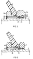
- the metal encapsulation 1 is omitted in FIGS. 2 and 3 and also the high voltage conductor 2 is only partially shown.
- Figure 1 is a disc-shaped, conical Isolierstoffbitzen 3 shown the high voltage conductor 2 concentric within the metal encapsulation 1 supported coaxially.
- the ring 4 also has a conical surface 6 on which the insulating material support 3 with an opposite direction conical surface 7 is pushed. To this The insulating material support 3 is clamped on the ring 4.
- the web 5 also forms a stop in the axial direction for the insulation support 3.
- a second ring 8 is provided, one formed as a bead circumferential web 9 on its circumference having.
- the two rings 4, 8 are of aligned bores 10, 11 enforced, through which a screw 12 protrudes, by means of of the two rings 4, 8 compressed in the axial direction will. This allows the insulating material support 3 between the webs 5, 9 of the rings 4, 8 in the axial direction be determined.
- a wedge body 13 is connected in one piece to the second ring 8, which surrounds the high-voltage conductor 2 in a ring.
- the Wedge body 13 acts with a conical surface 14 of the first Ring 4 together such that when the rings 4, 8 the wedge body 13 against one another against the high-voltage conductor 2 is pressed and thus both rings 4, 8 by static friction to be clamped to the high-voltage conductor 2.
- the insulating material support 3 carries in on its outer circumference a circumferential groove 16 a PTFE ring 15 on the inner wall the metal encapsulation 1 slides.
- the ring 15 can for example be divided and by one lying in the groove 16 Rubber ring 17 against the inner wall of the metal encapsulation 1 be pressed. This ensures that the ring 15th is constantly in connection with the metal encapsulation 1.
- Of the Ring 15 can also be used as a metal-filled, conductive plastic body and advantageously designed as a field control electrode be.
- the circumferential wedge body 13 can for better deformability have radially extending slots.
- the second ring 19 has a conical Surface 20 facing the high-voltage conductor 2 and with which a separate wedge body 21 cooperates.
- the wedge body 21 can, like the rings 18, 19, on the circumference of the high-voltage conductor 2 be formed all around. It However, it could also be provided that the wedge body 21 in several Split circular rings with a wedge-shaped cross-section. As a result, the wedge body 21 must be pressed against the surface of the high-voltage conductor 2 no force against the inherent stability a continuous annular wedge body applied will.
- Both the rings 4, 8, 18, 19 and the wedge bodies 13, 21 can be made of metal.
- the bulbous ones Bars 5, 9 of the rings then act in addition to their fastening function also as field control electrodes for controlling the High voltage potential. With such training then look at the bead-shaped parts of the rings as webs.
- the wedge bodies 13, 21 can also as an easily deformable insulating material body, for example be made of PTFE if this is dielectrically justifiable is. This can also be ensured, for example, by that the insulating material with a conductive, finely divided Material is filled to a certain minimum conductivity to create.
- the rings 18, 19 and the wedge body 21 have aligned bores 22, 23, 24, which are penetrated by screws 25, whereby the rings can be pressed axially against each other, so that by the wedge action between the surface 20 of the ring 19 and the wedge body 21 a radial pressure force on the wedge body 21 acts, this and thus the entire fastening device clamped on the high-voltage conductor 2.
- the insulating material support 3 lies on the wedge bodies 28, 29 backlash-free.
- the wedge body 29 has a radial with respect to the high voltage conductor 2 outward-facing wedge surface, the wedge body 28 a corresponding inwardly facing conical surface on, the conical surfaces to produce a Interact wedge action.
- the rings 26, 27 and the wedge bodies 28, 29 penetrated by aligned holes that a screw 30 absorb to generate an axial compressive force.
- a screw 30 absorbs to generate an axial compressive force.
- the rings 26, 27 Manufacture metal and also form as field control electrodes and the wedge bodies 28, 29 without endangering the dielectric To create security from an insulating material.
Landscapes
- Insulators (AREA)
- Insulating Bodies (AREA)
Description
Claims (8)
- Metallgekapselte Hochspannungsleitung mit einem Hochspannungsleiter (2), einer diesen koaxial umgebenden Metallkapselung (1) und mit wenigstens einer Befestigungsvorrichtung für einen scheibenförmigen Isolierstoffstützer (3), welche einen ersten und einen zweiten, jeweils zu dem Hochspannungsleiter (2) konzentrisch angeordneten Ring (4, 8, 18, 19, 26) mit je einem radial in bezug auf die Längsachse der Hochspannungsleitung vorragenden Steg (5, 9) aufweist, wobei ein Isolierstoffstützer (3) zwischen den Stegen (5, 9) der Ringe (4, 8, 18, 19, 26) festgelegt ist,
dadurch gekennzeichnet, daß
wenigstens einer der Ringe (4, 8, 18, 19, 26) den Hochspannungsleiter (2) unmittelbar umgibt und daß die Ringe (4, 8, 18, 19, 26) in axialer Richtung der Hochspannungsleitung gegeneinander gedrückt werden, wobei wenigstens ein erster Keilkörper (13, 21, 29) vorgesehen ist, der durch die axiale Andruckkraft, die das Gegeneinanderdrücken der Ringe (4, 8, 18, 19, 26) bewirkt, mittels Keilwirkung gegen den Hochspannungsleiter (2) preßbar ist und somit die Befestigungsvorrichtung an dem Hochspannungsleiter (2) festklemmt. - Metallgekapselte Hochspannungsleitung nach Anspruch 1,
dadurch gekennzeichnet, daß
zwischen dem ersten und dem zweiten Ring (4, 8, 18, 19, 26) ein dritter Ring (13, 29) mit konischer Außenkontur angeordnet ist, auf dem der Isolierstoffstützer (3) festgeklemmt ist. - Metallgekapselte Hochspannungsleitung nach Anspruch 2,
dadurch gekennzeichnet, daß
der dritte Ring (13, 29) mit dem ersten oder dem zweiten Ring (4, 8, 18, 19, 26) einstückig verbunden ist. - Metallgekapselte Hochspannungsleitung nach Anspruch 1 oder einem der folgenden,
dadurch gekennzeichnet, daß
der Isolierstoffstützer (3) an seinem äußeren Umfang einen Ring (15) trägt, der an der Innenwand der Metallkapselung gleitet. - Metallgekapselte Hochspannungsleitung nach Anspruch 1 oder einem der folgenden,
dadurch gekennzeichnet, daß
der erste Keilkörper (29) mit einem zweiten Keilkörper (28) zur Erzielung einer radialen Andruckkraft an den Hochspannunsleiter (2) zusammenwirkt. - Metallgekapselte Hochspannunsleitung nach Anspruch 1 oder einem der folgenden,
dadurch gekennzeichnet, daß
der erste (29) und insbesondere auch der zweite Keilkörper (28) in Axialrichtung der Hochspannungsleitung zwischen dem ersten (26) und dem zweiten Ring (27) angeordnet ist. - Metallgekapselte Hochspannungsleitung nach Anspruch 1 oder einem der folgenden,
dadurch gekennzeichnet, daß
der erste und/oder der zweite Keilkörper (13, 21, 28, 29) mit einem der Ringe (4, 8, 18, 19, 26) einstückig verbunden ist. - Metallgekapselte Hochspannungsleitung nach Anspruch 1 oder einem der folgenden,
dadurch gekennzeichnet, daß
der erste Keilkörper (13, 21, 29) von axial verlaufenden Schrauben (12, 25, 30) durchsetzt ist, die auch den ersten und zweiten Ring (4, 8, 18, 19, 26) durchsetzen.
Applications Claiming Priority (3)
| Application Number | Priority Date | Filing Date | Title |
|---|---|---|---|
| DE19502665 | 1995-01-20 | ||
| DE19502665A DE19502665C1 (de) | 1995-01-20 | 1995-01-20 | Metallgekapselte Hochspannungsleitung mit einer Befestigungsvorrichtung für einen Isolierstoffstützer |
| PCT/DE1996/000013 WO1996022624A1 (de) | 1995-01-20 | 1996-01-05 | Metallgekapselte hochspannungsleitung mit einer befestigungsvorrichtung für einen isolierstoffstützer |
Publications (2)
| Publication Number | Publication Date |
|---|---|
| EP0804825A1 EP0804825A1 (de) | 1997-11-05 |
| EP0804825B1 true EP0804825B1 (de) | 1998-09-16 |
Family
ID=7752531
Family Applications (1)
| Application Number | Title | Priority Date | Filing Date |
|---|---|---|---|
| EP96900254A Expired - Lifetime EP0804825B1 (de) | 1995-01-20 | 1996-01-05 | Metallgekapselte hochspannungsleitung mit einer befestigungsvorrichtung für einen isolierstoffstützer |
Country Status (5)
| Country | Link |
|---|---|
| US (1) | US5907123A (de) |
| EP (1) | EP0804825B1 (de) |
| CA (1) | CA2211102A1 (de) |
| DE (2) | DE19502665C1 (de) |
| WO (1) | WO1996022624A1 (de) |
Families Citing this family (4)
| Publication number | Priority date | Publication date | Assignee | Title |
|---|---|---|---|---|
| DE10010728C1 (de) * | 2000-02-29 | 2001-06-13 | Siemens Ag | Kapselungsbaustein für eine dreiphasige Sammelschiene einer Hochspannungsanlage |
| DE102013208405A1 (de) * | 2013-05-07 | 2014-11-13 | Schneider Electric Industries Sas | Hochspannungsbauteil |
| DE202014005301U1 (de) * | 2014-07-01 | 2014-07-17 | Abb Technology Ag | Kabelendverschluss zur Anbindung einer Schaltanlage an ein Hochspannungskabel |
| EP3093938B1 (de) * | 2015-05-12 | 2021-07-14 | Siemens Energy Global GmbH & Co. KG | Hochspannungs-durchführungssystem |
Family Cites Families (7)
| Publication number | Priority date | Publication date | Assignee | Title |
|---|---|---|---|---|
| CH536566A (de) * | 1971-09-16 | 1973-04-30 | Bbc Brown Boveri & Cie | Isoliergasgefüllt gekapselte elektrische Hochspannungsleitung |
| CH536567A (de) * | 1971-09-20 | 1973-04-30 | Bbc Brown Boveri & Cie | Isoliergasgefüllt gekapselte elektrische Hochspannungsleitung |
| DE2157101C2 (de) * | 1971-11-12 | 1982-04-29 | Siemens AG, 1000 Berlin und 8000 München | Abstützung eines in der Achse der Metallkapselung einer druckgasisolierten Hochspannungsschaltanlage verlaufenden Hochspannungsleiters mittels Isolatoren |
| SE382133B (sv) * | 1972-07-20 | 1976-01-12 | Licentia Gmbh | Metallkapslad, tryckgasisolerad hogspenningsledning |
| US4161621A (en) * | 1977-06-29 | 1979-07-17 | Westinghouse Electric Corp. | Spacer mount for a gas insulated transmission line |
| ATE126406T1 (de) * | 1992-11-13 | 1995-08-15 | Gec Alsthom T & D Ag | Gekapselte gasisolierte hochspannungsanlage und baugruppe einer solchen anlage. |
| FR2714204B1 (fr) * | 1993-12-21 | 1996-01-19 | Gec Alsthom T & D Sa | Câble monophasé à isolation gazeuse pour le transport d'électricité. |
-
1995
- 1995-01-20 DE DE19502665A patent/DE19502665C1/de not_active Expired - Fee Related
-
1996
- 1996-01-05 US US08/860,209 patent/US5907123A/en not_active Expired - Fee Related
- 1996-01-05 DE DE59600569T patent/DE59600569D1/de not_active Expired - Fee Related
- 1996-01-05 CA CA002211102A patent/CA2211102A1/en not_active Abandoned
- 1996-01-05 WO PCT/DE1996/000013 patent/WO1996022624A1/de not_active Ceased
- 1996-01-05 EP EP96900254A patent/EP0804825B1/de not_active Expired - Lifetime
Also Published As
| Publication number | Publication date |
|---|---|
| DE59600569D1 (de) | 1998-10-22 |
| EP0804825A1 (de) | 1997-11-05 |
| DE19502665C1 (de) | 1996-02-08 |
| WO1996022624A1 (de) | 1996-07-25 |
| CA2211102A1 (en) | 1996-07-25 |
| US5907123A (en) | 1999-05-25 |
Similar Documents
| Publication | Publication Date | Title |
|---|---|---|
| EP0897202B1 (de) | Steckverbinder für Koaxialkabel | |
| DE2348895C2 (de) | Verbindung für Starkstromkabel | |
| DE2157101C2 (de) | Abstützung eines in der Achse der Metallkapselung einer druckgasisolierten Hochspannungsschaltanlage verlaufenden Hochspannungsleiters mittels Isolatoren | |
| DE4139100C1 (en) | Plug and socket appts. - has elastic deformable damping piece(s) radially tensioned against contact support as well as socket when coupled together | |
| DE1905182A1 (de) | Schnellanschluss fuer Koaxialkabel | |
| DE60302953T2 (de) | Verbinder für zwei elektrische Energiekabel und Verbindung mit einem solchen Verbinder | |
| EP0674375B1 (de) | Lösbare Kupplungsvorrichtung zwischen zwei miteinander fluchtenden elektrischen Leitern | |
| EP0804825B1 (de) | Metallgekapselte hochspannungsleitung mit einer befestigungsvorrichtung für einen isolierstoffstützer | |
| EP0888657B1 (de) | Gasisolierte energieübertragungsanlage mit in abständen axial fixiertem innenleiter | |
| EP0643255B1 (de) | Elektrische Lampe | |
| EP1158638A1 (de) | Anordnung zum elektrisch leitenden Verbinden der Leiter von zwei Hochspanungskabeln | |
| EP2107657A2 (de) | Kabelverschraubung | |
| DE2445898C2 (de) | Verbindung eines Erdungsschirms | |
| DE2263060A1 (de) | Spannhuelsenanordnung | |
| DE2547914A1 (de) | Kabelverschraubung mit zugentlastung | |
| DE3445905C2 (de) | ||
| DE2430066C3 (de) | Mehrphasige elektrische Verbindungsoder Abzweigklemme | |
| DE3127284C2 (de) | Batterieklemme | |
| DE3014600C2 (de) | Anschlußarmatur für einen Isolatorstab aus glasfaserverstärktem Kunststoff | |
| DE3886916T2 (de) | Elektrischer Kabelendverbinder zum elektrischen Verbinden von einadrigen Kabeln mit einem Anschluss einer Installation. | |
| EP0210126B1 (de) | Kuppelkontakstück für eine Steckverbindung zwischen zwei zylindrischen Leitern einer gekapselten, drukgasisolierten Hochspannungsschaltanlage. | |
| EP0638975A1 (de) | Muffenkopf mit mehreren geteilten Kabeleinführungen | |
| DE2451853B2 (de) | Isolierstützenanordnung für einen HF-Koaxialleitungsabschnitt | |
| DE2740232C3 (de) | Verbindungsmuffe | |
| DE19938303C2 (de) | Vorrichtung zum Verbinden von insbesondere rohrförmigen elektrischen Leitern eines Energieübertragungssystems |
Legal Events
| Date | Code | Title | Description |
|---|---|---|---|
| PUAI | Public reference made under article 153(3) epc to a published international application that has entered the european phase |
Free format text: ORIGINAL CODE: 0009012 |
|
| 17P | Request for examination filed |
Effective date: 19970704 |
|
| AK | Designated contracting states |
Kind code of ref document: A1 Designated state(s): CH DE FR GB IT LI |
|
| GRAG | Despatch of communication of intention to grant |
Free format text: ORIGINAL CODE: EPIDOS AGRA |
|
| GRAG | Despatch of communication of intention to grant |
Free format text: ORIGINAL CODE: EPIDOS AGRA |
|
| GRAH | Despatch of communication of intention to grant a patent |
Free format text: ORIGINAL CODE: EPIDOS IGRA |
|
| 17Q | First examination report despatched |
Effective date: 19980224 |
|
| GRAH | Despatch of communication of intention to grant a patent |
Free format text: ORIGINAL CODE: EPIDOS IGRA |
|
| GRAA | (expected) grant |
Free format text: ORIGINAL CODE: 0009210 |
|
| AK | Designated contracting states |
Kind code of ref document: B1 Designated state(s): CH DE FR GB IT LI |
|
| REG | Reference to a national code |
Ref country code: CH Ref legal event code: EP |
|
| REF | Corresponds to: |
Ref document number: 59600569 Country of ref document: DE Date of ref document: 19981022 |
|
| ET | Fr: translation filed | ||
| REG | Reference to a national code |
Ref country code: CH Ref legal event code: NV Representative=s name: SIEMENS SCHWEIZ AG |
|
| GBT | Gb: translation of ep patent filed (gb section 77(6)(a)/1977) |
Effective date: 19981216 |
|
| PLBE | No opposition filed within time limit |
Free format text: ORIGINAL CODE: 0009261 |
|
| STAA | Information on the status of an ep patent application or granted ep patent |
Free format text: STATUS: NO OPPOSITION FILED WITHIN TIME LIMIT |
|
| 26N | No opposition filed | ||
| PGFP | Annual fee paid to national office [announced via postgrant information from national office to epo] |
Ref country code: GB Payment date: 20000113 Year of fee payment: 5 |
|
| PGFP | Annual fee paid to national office [announced via postgrant information from national office to epo] |
Ref country code: CH Payment date: 20000413 Year of fee payment: 5 |
|
| PG25 | Lapsed in a contracting state [announced via postgrant information from national office to epo] |
Ref country code: GB Free format text: LAPSE BECAUSE OF NON-PAYMENT OF DUE FEES Effective date: 20010105 |
|
| PGFP | Annual fee paid to national office [announced via postgrant information from national office to epo] |
Ref country code: FR Payment date: 20010112 Year of fee payment: 6 |
|
| PG25 | Lapsed in a contracting state [announced via postgrant information from national office to epo] |
Ref country code: LI Free format text: LAPSE BECAUSE OF NON-PAYMENT OF DUE FEES Effective date: 20010131 Ref country code: CH Free format text: LAPSE BECAUSE OF NON-PAYMENT OF DUE FEES Effective date: 20010131 |
|
| PGFP | Annual fee paid to national office [announced via postgrant information from national office to epo] |
Ref country code: DE Payment date: 20010319 Year of fee payment: 6 |
|
| GBPC | Gb: european patent ceased through non-payment of renewal fee |
Effective date: 20010105 |
|
| REG | Reference to a national code |
Ref country code: CH Ref legal event code: PL |
|
| PG25 | Lapsed in a contracting state [announced via postgrant information from national office to epo] |
Ref country code: DE Free format text: LAPSE BECAUSE OF NON-PAYMENT OF DUE FEES Effective date: 20020801 |
|
| PG25 | Lapsed in a contracting state [announced via postgrant information from national office to epo] |
Ref country code: FR Free format text: LAPSE BECAUSE OF NON-PAYMENT OF DUE FEES Effective date: 20020930 |
|
| REG | Reference to a national code |
Ref country code: FR Ref legal event code: ST |
|
| PG25 | Lapsed in a contracting state [announced via postgrant information from national office to epo] |
Ref country code: IT Free format text: LAPSE BECAUSE OF NON-PAYMENT OF DUE FEES;WARNING: LAPSES OF ITALIAN PATENTS WITH EFFECTIVE DATE BEFORE 2007 MAY HAVE OCCURRED AT ANY TIME BEFORE 2007. THE CORRECT EFFECTIVE DATE MAY BE DIFFERENT FROM THE ONE RECORDED. Effective date: 20050105 |