EP0804798B1 - Transformateur polyphase - Google Patents
Transformateur polyphase Download PDFInfo
- Publication number
- EP0804798B1 EP0804798B1 EP96900264A EP96900264A EP0804798B1 EP 0804798 B1 EP0804798 B1 EP 0804798B1 EP 96900264 A EP96900264 A EP 96900264A EP 96900264 A EP96900264 A EP 96900264A EP 0804798 B1 EP0804798 B1 EP 0804798B1
- Authority
- EP
- European Patent Office
- Prior art keywords
- winding
- sections
- phase transformer
- transformer
- tank
- Prior art date
- Legal status (The legal status is an assumption and is not a legal conclusion. Google has not performed a legal analysis and makes no representation as to the accuracy of the status listed.)
- Expired - Lifetime
Links
- 238000004804 winding Methods 0.000 claims description 88
- 239000002826 coolant Substances 0.000 claims description 4
- 230000004907 flux Effects 0.000 claims description 4
- 239000004020 conductor Substances 0.000 description 7
- 239000000463 material Substances 0.000 description 6
- 238000001816 cooling Methods 0.000 description 4
- 238000004519 manufacturing process Methods 0.000 description 4
- 239000012876 carrier material Substances 0.000 description 2
- 238000010586 diagram Methods 0.000 description 2
- 238000010276 construction Methods 0.000 description 1
- 230000008878 coupling Effects 0.000 description 1
- 238000010168 coupling process Methods 0.000 description 1
- 238000005859 coupling reaction Methods 0.000 description 1
- 238000005516 engineering process Methods 0.000 description 1
- 230000002349 favourable effect Effects 0.000 description 1
- 238000009434 installation Methods 0.000 description 1
- 238000000926 separation method Methods 0.000 description 1
- 239000002887 superconductor Substances 0.000 description 1
Images


Classifications
-
- H—ELECTRICITY
- H01—ELECTRIC ELEMENTS
- H01F—MAGNETS; INDUCTANCES; TRANSFORMERS; SELECTION OF MATERIALS FOR THEIR MAGNETIC PROPERTIES
- H01F36/00—Transformers with superconductive windings or with windings operating at cryogenic temperature
-
- Y—GENERAL TAGGING OF NEW TECHNOLOGICAL DEVELOPMENTS; GENERAL TAGGING OF CROSS-SECTIONAL TECHNOLOGIES SPANNING OVER SEVERAL SECTIONS OF THE IPC; TECHNICAL SUBJECTS COVERED BY FORMER USPC CROSS-REFERENCE ART COLLECTIONS [XRACs] AND DIGESTS
- Y02—TECHNOLOGIES OR APPLICATIONS FOR MITIGATION OR ADAPTATION AGAINST CLIMATE CHANGE
- Y02E—REDUCTION OF GREENHOUSE GAS [GHG] EMISSIONS, RELATED TO ENERGY GENERATION, TRANSMISSION OR DISTRIBUTION
- Y02E40/00—Technologies for an efficient electrical power generation, transmission or distribution
- Y02E40/60—Superconducting electric elements or equipment; Power systems integrating superconducting elements or equipment
Definitions
- the invention relates to a multi-phase transformer a superconducting toroidal winding.
- the torus winding in which favorable management of the main field is possible.
- the torus winding is made from a tubular material.
- Such a torus winding requires a complex one Manufacturing engineering.
- the torus winding is to achieve superconductivity in a cyrostat vessel, especially one Tank, boiler or other suitable vessel, that contains the cooling medium.
- a cyrostat vessel especially one Tank, boiler or other suitable vessel, that contains the cooling medium.
- CH-PS 411 124 is a superconducting transformer known, whose windings are arranged in a toroidal shape, wherein the cross section of the windings is annular in shape having.
- From DE-OS 14 88 322 is a transformer superconducting windings known in which on a common ring-shaped closed core coaxially one inside the other nested windings are arranged. In addition there is one DC winding is provided, which in partial windings is divided into that due to the change in them flows in the magnetic circuit induce mutual voltages cancel.
- a three-phase transformer is known from DE-AS 12 04 322, whose windings in a known manner a five-legged core are arranged.
- the core is out three parts.
- Each core part is one separate container assigned, each with a Flange is provided.
- the transformer is for the purpose of Transport with its core and container parts can be dismantled.
- the invention has for its object a superconducting Specify multi-phase transformer, the is particularly easy to manufacture and inexpensive to handle.
- the problem is solved with a superconducting multiphase Transformer with its torus winding in one Boiler with a cooling medium is arranged, the torus winding along its course for each phase in winding sections is divided, the magnetic fluxes of the Winding sections closed by at least one yoke are, and with the boiler at separation points of the torus winding is divided into boiler sections with a yoke.
- the yokes are preferably arranged between the boiler sections. This simplifies the assembly of the transformer. In addition, the yokes can then be at a different temperature than inside the boiler, e.g. at room temperature, operate.
- the boiler sections can be connected to one another with flanges be. These are then preferably arranged in the area of the yokes, which enables simple, space-saving installation is.
- the stretched torus winding can also be folded.
- the boiler is very compact in this way. This can be also cheap when optimizing the required boiler volume impact on the transformer. By folding are the smallest transformer sizes with the same electrical Values achievable.
- the transformer is preferably three-phase. He is therefore particularly suitable for use in existing Power distribution networks.
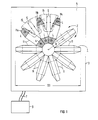
- FIG. 1 shows a superconducting transformer 1, which in one serving as a cyrostat vessel 3 is arranged.
- the Schematic diagram shows that the interior 5 of the housing 3rd connected to a cooling device 9 via supply lines 7 is.
- the cooling device 9 cools this in the housing 3 contained cooling medium to the required low temperature down.
- the transformer 1 has a winding which in the manner of a torus winding, similar to a closed one Hose ring, is built up.
- the torus winding becomes present of a plurality of first winding elements 11, 11a, 11b, 11c formed, which are joined together in a sector-like manner are. They form a polygonal arrangement.
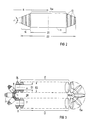
- the first winding element 11 is initially ring-like with an inner diameter D1 and one outer diameter D2 built.
- the first winding element 11 concentric tube conductor 13 arranged coaxially the serve as a conductor for the winding.
- the winding element 11 is shown with three tube conductors 13, the one for a three winding transformer or also a double-concentric arrangement of a two-winding transformer can serve.
- the tube conductors are of course made of a superconducting Material, e.g. a high or low temperature conductor (HTL or TTL).
- HTL high or low temperature conductor
- the winding element 11 has winding elements a profile with a wedge or trapezoidal cross-section on. In contrast to an O-ring with a circular cross-section can be spoken of a trapezoidal ring.
- the corresponding trapezoidal angle ⁇ depends on that for the Torus winding provided geometry, especially the radius and the number of winding elements 11. Is preferred the winding element 11 - as shown - rotationally symmetrical trained so that when assembling winding elements 11a, 11b, 11c no special position can be provided got to. However, they are also asymmetrical shapes or in Contrary to the circular ring shape, square or oval versions possible, which are not shown.
- FIG. 1 shows how a predetermined number, namely ten, winding elements 11 to 11c polygonal to a torus winding are put together.
- the number of first winding elements 11 to 11c high. This is a radial one Dodge the magnetic flux between the first winding elements 11 to 11c avoided.
- the first winding elements in cross section form completely circular sector, so that the Spaces Z are almost completely avoided.
- first winding elements 11a, 11b, 11c arranged shield body 15 (shown in dashed lines).
- the shield body 15 are approximately saddle-shaped and each overlap Gap Z between two winding elements 11a and 11b or 11b and 11c. With S the courses are the resulting ones Eddy current paths in the screen bodies 15 with respect to the drawn idle current flow L in the first Winding elements lla to llc shown qualitatively.
- the shield body 15 are also made of a superconducting electromagnetic material manufactured. You can also go through an area coverage of a correspondingly shaped carrier material can be realized with superconducting material.
- the carrier material can also be of linear superconductors be formed.
- the result is a skeletal Carrier. If necessary, the screen body 15 even be carried out in such a skeleton construction. The individual conductors or wires of the skeleton are then electrical connected with each other.
- the first winding elements 11a to 11c and the screens 15 can with each other by fasteners, not shown, .
- a large polygon diameter Avoiding D3 can lead to a Transformer la according to FIG 3 with an elongated torus winding be inexpensive (representation without housing). It can namely a smaller radius R compared to that from FIG. 1 is used be two half polygons with two straight sections 17 are connected.
- the straight sections 17 can of course from simple concentrically arranged straight tube pieces can be formed (not shown).
- the straight sections can also be used of the new first winding elements 11 are formed. These can namely in the area of their inner diameter D1 - as can be seen in FIG. 2 - forming a straight line River tube to be just put together. To this Way, the entire winding arrangement is of a standard first winding element 11 is formed.
- the umbrella body 15a can also cover several winding elements 11, see above that a half-shell-like screen 15a is formed as shown here is.
- first winding elements 11 straight and Angles can be arranged to each other, are arbitrary Designs for winding a transformer or one Coil can be generated. This is particularly convenient when certain Sizes or designs must be observed.
- FIGS. 4 and 5 show a further embodiment of a superconducting Transformer 1b, in which the stretched winding arrangement 3 is additionally folded.
- the two Figures show the boiler 19 of the transformer 1b, the an example of a cooling system connection 21 and a high-voltage bushing 23 has.
- This version points 3 a reduced overall length, which without additional Components can be achieved.
- the winding arrangement with the new winding elements 11 is namely a Link chain deformable.
- At the additional kinks 25 are also preferred umbrella bodies 15b for flow control intended.
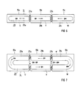
- FIG. 6, 7 and 8, 9 show multi-phase superconducting transformers 1c and 1d in a side and top view.
- the Winding 29 is only shown in principle. It is there to recognize that for all phases U, V, W - present here three - only a common toroidal winding 29 is provided. It is in individual winding sections 29a to 29c for the individual phases U, V, W divided.
- the winding sections 29a to 29c of phases U, V, W are represented by yokes 27a, 27b (figures 6 and 7) separated from each other.
- the stretched one shown Torus winding 29 of the transformer 1c is in this embodiment divided transversely in their stretching direction, so that only two yokes 27a, b are necessary. Phase V therefore divides into two separate winding sections 29b on.
- the resulting magnetic fluxes ⁇ u, ⁇ v, ⁇ w are in the Figures drawn.
- the flow direction of the middle phase V is opposite to the positive flow directions of phases U and W. chosen so that by vectorial addition to the Jochen 27a, 27b the smallest possible rivers ⁇ u, ⁇ v, ⁇ w arise.
- the division into the winding sections 29a, 29b, 29c serves at the same time as dividing the boiler into three boiler sections 19a, 19b, 19c.
- the boiler sections 19a, 19b, 19c are on their adjoining surfaces in the area of the yokes 27a, 27b with flanges not shown in detail (according to the state the technology), so that a good mechanical and magnetic Coupling of the units formed in a coaxial manner possible is.
- a transformer 1c of this type thus has several parts transportable, which is particularly the case with large transformers is an advantage because there is always transport size and - weight is a problem.
- the Yokes 27a, 27b and the flanges advantageously form a structural Unity.
- the yokes 27a, 27b are made of conventional ones Transformer sheet made and outside between the boiler sections 19a, 19b, 19c arranged so that they are normal Ambient temperatures, i.e. between 0 and 100 ° C, operate.
- the boiler sections 19a, 19b, 19c can in the present simple division of the torus winding 29 as a cuboid be, which makes them easy to manufacture. It is also a star-shaped subdivision of the entire transformer conceivable in which a star-shaped depending on the number of phases split cylindrical kettle is used.
- This exemplary three-phase arrangement is also according to the Above versions can also be produced in a folded version.
- the folded version according to FIG. 9 come here the winding sections 29a and 29c of phases U and W side by side to lie. These can then also be used with advantage a common boiler section 19d Kessel shape can be cylindrical or cuboid be. In this version there is even only one thing in common Yoke 27 required.
Landscapes
- Engineering & Computer Science (AREA)
- Power Engineering (AREA)
- Coils Of Transformers For General Uses (AREA)
- Containers, Films, And Cooling For Superconductive Devices (AREA)
Claims (8)
- Transformateur polyphasé (1c, 1d), qui est placé avec son enroulement torique supraconducteur dans une cuve contenant un produit de refroidissement, dans lequell'enroulement torique (29) est divisé en tronçons d'enroulement (29a à 29c) pour chaque phase (U, V, W),les flux magnétiques (ϕu, ϕv, ϕw) des tronçons d'enroulement (29a à 29c) sont fermés par au moins une culasse (27, 27a),la cuve est divisée dans la zone de la ou des culasses (27, 27a) en tronçons de cuve (19a, 19b, 19c), etchaque tronçon d'enroulement (29a à 29c) est placé dans un tronçon de cuve (19a, 19b, 19c) respectivement associé.
- Transformateur polyphasé selon la revendication 1, dans lequel la ou les culasses (27, 27a) sont disposées entre les tronçons de cuve (19a à 19d).
- Transformateur polyphasé selon la revendication 1 ou 2, dans lequel les tronçons de cuve (19a à 19d) sont assemblés par des brides.
- Transformateur polyphasé selon la revendication 1, 2 ou 3, dans lequel il est prévu pour au moins deux tronçons d'enroulement (29a à 29c), notamment pour tous, une culasse commune (27, 27a).
- Transformateur polyphasé selon l'une des revendications 1 à 4, dans lequel l'enroulement torique (29) est allongé et est divisé dans son sens d'allongement par une division transversale en tronçons d'enroulement (29a à 29c), au moins une phase (U, V, W) comportant alors éventuellement deux tronçons d'enroulement (29b) qui sont reliés par deux culasses (27).
- Transformateur polyphasé selon la revendication 5, dans lequel l'enroulement torique (29) allongé est plié dans la zone de son allongement de telle sorte que ses extrémités libres se trouvent parallèles l'une à l'autre.
- Transformateur polyphasé selon l'une des revendications 1 à 5, qui est conçu triphasé.
- Transformateur polyphasé selon l'une des revendications 1 à 7, dans lequel la cuve peut être démontée suivant ses tronçons de cuve (29a à 29c) pour être transportée.
Applications Claiming Priority (3)
| Application Number | Priority Date | Filing Date | Title |
|---|---|---|---|
| DE19501082 | 1995-01-16 | ||
| DE19501082A DE19501082C1 (de) | 1995-01-16 | 1995-01-16 | Mehrphasiger Transformator |
| PCT/DE1996/000023 WO1996022607A1 (fr) | 1995-01-16 | 1996-01-10 | Transformateur polyphase |
Publications (2)
| Publication Number | Publication Date |
|---|---|
| EP0804798A1 EP0804798A1 (fr) | 1997-11-05 |
| EP0804798B1 true EP0804798B1 (fr) | 1998-10-28 |
Family
ID=7751574
Family Applications (1)
| Application Number | Title | Priority Date | Filing Date |
|---|---|---|---|
| EP96900264A Expired - Lifetime EP0804798B1 (fr) | 1995-01-16 | 1996-01-10 | Transformateur polyphase |
Country Status (5)
| Country | Link |
|---|---|
| US (1) | US5909167A (fr) |
| EP (1) | EP0804798B1 (fr) |
| JP (1) | JPH10513607A (fr) |
| DE (2) | DE19501082C1 (fr) |
| WO (1) | WO1996022607A1 (fr) |
Families Citing this family (15)
| Publication number | Priority date | Publication date | Assignee | Title |
|---|---|---|---|---|
| NZ333599A (en) | 1996-05-29 | 2000-05-26 | Abb Ab | High voltage AC machine with grounded windings with semiconductive layer around windings |
| AU3052997A (en) | 1996-05-29 | 1998-01-05 | Asea Brown Boveri Ab | Rotating electrical machine comprising high-voltage stator winding and elongated support devices supporting the winding and method for manufacturing such machine |
| SE9602079D0 (sv) | 1996-05-29 | 1996-05-29 | Asea Brown Boveri | Roterande elektriska maskiner med magnetkrets för hög spänning och ett förfarande för tillverkning av densamma |
| SE9704413D0 (sv) | 1997-02-03 | 1997-11-28 | Asea Brown Boveri | Krafttransformator/reaktor |
| SE9704412D0 (sv) | 1997-02-03 | 1997-11-28 | Asea Brown Boveri | Krafttransformator/reaktor |
| SE510452C2 (sv) | 1997-02-03 | 1999-05-25 | Asea Brown Boveri | Transformator med spänningsregleringsorgan |
| SE513083C2 (sv) | 1997-09-30 | 2000-07-03 | Abb Ab | Synkronkompensatoranläggning jämte användning av dylik samt förfarande för faskompensation i ett högspänt kraftfält |
| SE513555C2 (sv) | 1997-11-27 | 2000-10-02 | Abb Ab | Förfarande för applicering av ett rörorgan i ett utrymme i en roterande elektrisk maskin och roterande elektrisk maskin enligt förfarandet |
| GB2331858A (en) | 1997-11-28 | 1999-06-02 | Asea Brown Boveri | A wind power plant |
| GB2331853A (en) | 1997-11-28 | 1999-06-02 | Asea Brown Boveri | Transformer |
| SE516002C2 (sv) | 2000-03-01 | 2001-11-05 | Abb Ab | Roterande elektrisk maskin samt förfarande för framställning av en statorlindning |
| SE516442C2 (sv) | 2000-04-28 | 2002-01-15 | Abb Ab | Stationär induktionsmaskin och kabel därför |
| BRPI0822691A2 (pt) * | 2008-05-13 | 2015-07-07 | Abb Technology Ag | Núcleo em forma de anel modular |
| JP5364356B2 (ja) * | 2008-12-11 | 2013-12-11 | 三菱重工業株式会社 | 超電導コイル装置 |
| US11070123B2 (en) * | 2017-07-07 | 2021-07-20 | The Boeing Compan | Energy storage and energy storage device |
Family Cites Families (8)
| Publication number | Priority date | Publication date | Assignee | Title |
|---|---|---|---|---|
| DE937184C (de) * | 1937-12-16 | 1955-12-29 | Siemens Ag | Schaltdrossel |
| DE1204322B (de) * | 1958-06-11 | 1965-11-04 | English Electric Co Ltd | Leistungstransformator |
| AT236513B (de) * | 1962-01-20 | 1964-10-26 | Transformator mit Wicklungen aus supraleitendem Material | |
| DE1488322A1 (de) * | 1964-01-17 | 1969-04-10 | Siemens Ag | Transformator mit supraleitenden Wicklungen |
| JPS5912004B2 (ja) * | 1976-07-05 | 1984-03-19 | 誠 桂井 | 準超電導方式コイル |
| JPS6024491A (ja) * | 1983-07-20 | 1985-02-07 | 株式会社日立製作所 | 核融合装置用トロイダルコイル |
| JPS62105080A (ja) * | 1985-11-01 | 1987-05-15 | 株式会社日立製作所 | トロイダル磁場コイル |
| FR2652959B1 (fr) * | 1989-10-09 | 1993-12-17 | Gec Alsthom Sa | Dispositif de stockage electromagnetique dans des enroulements supraconducteurs en forme de tore. |
-
1995
- 1995-01-16 DE DE19501082A patent/DE19501082C1/de not_active Expired - Fee Related
-
1996
- 1996-01-10 EP EP96900264A patent/EP0804798B1/fr not_active Expired - Lifetime
- 1996-01-10 JP JP8521963A patent/JPH10513607A/ja active Pending
- 1996-01-10 DE DE59600738T patent/DE59600738D1/de not_active Expired - Fee Related
- 1996-01-10 WO PCT/DE1996/000023 patent/WO1996022607A1/fr not_active Ceased
-
1997
- 1997-07-16 US US08/895,402 patent/US5909167A/en not_active Expired - Lifetime
Also Published As
| Publication number | Publication date |
|---|---|
| DE19501082C1 (de) | 1996-11-14 |
| WO1996022607A1 (fr) | 1996-07-25 |
| DE59600738D1 (de) | 1998-12-03 |
| JPH10513607A (ja) | 1998-12-22 |
| EP0804798A1 (fr) | 1997-11-05 |
| US5909167A (en) | 1999-06-01 |
Similar Documents
| Publication | Publication Date | Title |
|---|---|---|
| EP0804798B1 (fr) | Transformateur polyphase | |
| EP0804797B1 (fr) | Transformateur supraconducteur | |
| WO2017005619A1 (fr) | Transformateur pourvu de bobines supraconductrices | |
| DE102018206389A1 (de) | Dreiphasiger Transformator | |
| DE1513870B2 (de) | Hochspannungsstromwandler | |
| DE3914731A1 (de) | Drehstrommotor grossen durchmessers mit teilfugen im staender | |
| EP2182533B1 (fr) | Transformateur | |
| DE102004008961B4 (de) | Spulenkörper für geschlossenen magnetischen Kern und daraus hergestellte Entstördrossel | |
| EP0127119A1 (fr) | Appareil électromagnétique pour circuit de puissance à haute fréquence, en particulier transformateur ou bobine réactance | |
| DE723560C (de) | Transformator | |
| DE731977C (de) | Hochspannungstrockentransformator | |
| DE2843608C2 (de) | Transformator, insbesondere Spannungswandler oder Prüftransformator | |
| DE2627314C2 (de) | Wicklung für Transformatoren | |
| DE3920732A1 (de) | Elektrisches induktionsgeraet | |
| DE880770C (de) | Drehstromdrosselspule | |
| DE2841592C2 (de) | Stufenwicklung für Transformatoren und Drosseln für sehr große Ströme | |
| DE2554514C3 (de) | Transformator für große elektrische Leistungen | |
| DE69231948T2 (de) | Ein hochspannungsstromtransformator mit automatisierter isolationsherstellung und lagerung | |
| DE1638610C3 (de) | Luftdrossel-Ringspule mit veränderlicher Induktivität | |
| DE968893C (de) | Stufenspannungswandler | |
| AT129531B (de) | Hochspannungstransformator, insbesondere Spannungsmeßwandler, mit einem einteiligen Spulenkasten und einer darin befindlichen Oberspannungswicklung, die von einem dicht anschließenden, leitenden Mantel umgeben sind. | |
| DE126730C (fr) | ||
| AT209983B (de) | Strombegrenzungsdrossel | |
| DE565175C (de) | Anordnung zur Regelung der Spannung nach Groesse in Mehrphasentransformatoren | |
| DE1513916B2 (de) | Wicklungsaufbau mit mehreren axial übereinanderliegenden Teilwicklungen für Transformatoren und Drosselspulen |
Legal Events
| Date | Code | Title | Description |
|---|---|---|---|
| PUAI | Public reference made under article 153(3) epc to a published international application that has entered the european phase |
Free format text: ORIGINAL CODE: 0009012 |
|
| 17P | Request for examination filed |
Effective date: 19970206 |
|
| AK | Designated contracting states |
Kind code of ref document: A1 Designated state(s): BE CH DE FR GB IT LI NL SE |
|
| GRAG | Despatch of communication of intention to grant |
Free format text: ORIGINAL CODE: EPIDOS AGRA |
|
| GRAG | Despatch of communication of intention to grant |
Free format text: ORIGINAL CODE: EPIDOS AGRA |
|
| GRAH | Despatch of communication of intention to grant a patent |
Free format text: ORIGINAL CODE: EPIDOS IGRA |
|
| 17Q | First examination report despatched |
Effective date: 19980317 |
|
| GRAH | Despatch of communication of intention to grant a patent |
Free format text: ORIGINAL CODE: EPIDOS IGRA |
|
| GRAA | (expected) grant |
Free format text: ORIGINAL CODE: 0009210 |
|
| AK | Designated contracting states |
Kind code of ref document: B1 Designated state(s): BE CH DE FR GB IT LI NL SE |
|
| REG | Reference to a national code |
Ref country code: CH Ref legal event code: NV Representative=s name: SIEMENS SCHWEIZ AG Ref country code: CH Ref legal event code: EP |
|
| REF | Corresponds to: |
Ref document number: 59600738 Country of ref document: DE Date of ref document: 19981203 |
|
| ET | Fr: translation filed | ||
| ITF | It: translation for a ep patent filed | ||
| GBT | Gb: translation of ep patent filed (gb section 77(6)(a)/1977) |
Effective date: 19990113 |
|
| PLBE | No opposition filed within time limit |
Free format text: ORIGINAL CODE: 0009261 |
|
| STAA | Information on the status of an ep patent application or granted ep patent |
Free format text: STATUS: NO OPPOSITION FILED WITHIN TIME LIMIT |
|
| 26N | No opposition filed | ||
| REG | Reference to a national code |
Ref country code: GB Ref legal event code: IF02 |
|
| PGFP | Annual fee paid to national office [announced via postgrant information from national office to epo] |
Ref country code: GB Payment date: 20030114 Year of fee payment: 8 |
|
| PGFP | Annual fee paid to national office [announced via postgrant information from national office to epo] |
Ref country code: NL Payment date: 20030120 Year of fee payment: 8 |
|
| PGFP | Annual fee paid to national office [announced via postgrant information from national office to epo] |
Ref country code: BE Payment date: 20030128 Year of fee payment: 8 |
|
| PG25 | Lapsed in a contracting state [announced via postgrant information from national office to epo] |
Ref country code: GB Free format text: LAPSE BECAUSE OF NON-PAYMENT OF DUE FEES Effective date: 20040110 |
|
| PG25 | Lapsed in a contracting state [announced via postgrant information from national office to epo] |
Ref country code: BE Free format text: LAPSE BECAUSE OF NON-PAYMENT OF DUE FEES Effective date: 20040131 |
|
| BERE | Be: lapsed |
Owner name: *SIEMENS A.G. Effective date: 20040131 |
|
| PG25 | Lapsed in a contracting state [announced via postgrant information from national office to epo] |
Ref country code: NL Free format text: LAPSE BECAUSE OF NON-PAYMENT OF DUE FEES Effective date: 20040801 |
|
| GBPC | Gb: european patent ceased through non-payment of renewal fee |
Effective date: 20040110 |
|
| NLV4 | Nl: lapsed or anulled due to non-payment of the annual fee |
Effective date: 20040801 |
|
| PG25 | Lapsed in a contracting state [announced via postgrant information from national office to epo] |
Ref country code: IT Free format text: LAPSE BECAUSE OF NON-PAYMENT OF DUE FEES;WARNING: LAPSES OF ITALIAN PATENTS WITH EFFECTIVE DATE BEFORE 2007 MAY HAVE OCCURRED AT ANY TIME BEFORE 2007. THE CORRECT EFFECTIVE DATE MAY BE DIFFERENT FROM THE ONE RECORDED. Effective date: 20050110 |
|
| PGFP | Annual fee paid to national office [announced via postgrant information from national office to epo] |
Ref country code: SE Payment date: 20070111 Year of fee payment: 12 |
|
| PGFP | Annual fee paid to national office [announced via postgrant information from national office to epo] |
Ref country code: DE Payment date: 20070322 Year of fee payment: 12 |
|
| PGFP | Annual fee paid to national office [announced via postgrant information from national office to epo] |
Ref country code: CH Payment date: 20070403 Year of fee payment: 12 |
|
| PGFP | Annual fee paid to national office [announced via postgrant information from national office to epo] |
Ref country code: FR Payment date: 20070123 Year of fee payment: 12 |
|
| REG | Reference to a national code |
Ref country code: CH Ref legal event code: PL |
|
| EUG | Se: european patent has lapsed | ||
| PG25 | Lapsed in a contracting state [announced via postgrant information from national office to epo] |
Ref country code: CH Free format text: LAPSE BECAUSE OF NON-PAYMENT OF DUE FEES Effective date: 20080131 Ref country code: LI Free format text: LAPSE BECAUSE OF NON-PAYMENT OF DUE FEES Effective date: 20080131 Ref country code: DE Free format text: LAPSE BECAUSE OF NON-PAYMENT OF DUE FEES Effective date: 20080801 |
|
| REG | Reference to a national code |
Ref country code: FR Ref legal event code: ST Effective date: 20081029 |
|
| PG25 | Lapsed in a contracting state [announced via postgrant information from national office to epo] |
Ref country code: SE Free format text: LAPSE BECAUSE OF NON-PAYMENT OF DUE FEES Effective date: 20080111 |
|
| PG25 | Lapsed in a contracting state [announced via postgrant information from national office to epo] |
Ref country code: FR Free format text: LAPSE BECAUSE OF NON-PAYMENT OF DUE FEES Effective date: 20080131 |