EP0804745B1 - Procede et dispositif de mesure de vitesses sans contact sur des surfaces - Google Patents
Procede et dispositif de mesure de vitesses sans contact sur des surfaces Download PDFInfo
- Publication number
- EP0804745B1 EP0804745B1 EP95937837A EP95937837A EP0804745B1 EP 0804745 B1 EP0804745 B1 EP 0804745B1 EP 95937837 A EP95937837 A EP 95937837A EP 95937837 A EP95937837 A EP 95937837A EP 0804745 B1 EP0804745 B1 EP 0804745B1
- Authority
- EP
- European Patent Office
- Prior art keywords
- signal
- frequency
- speed
- pass filter
- signal power
- Prior art date
- Legal status (The legal status is an assumption and is not a legal conclusion. Google has not performed a legal analysis and makes no representation as to the accuracy of the status listed.)
- Expired - Lifetime
Links
Images

Classifications
-
- G—PHYSICS
- G01—MEASURING; TESTING
- G01C—MEASURING DISTANCES, LEVELS OR BEARINGS; SURVEYING; NAVIGATION; GYROSCOPIC INSTRUMENTS; PHOTOGRAMMETRY OR VIDEOGRAMMETRY
- G01C22/00—Measuring distance traversed on the ground by vehicles, persons, animals or other moving solid bodies, e.g. using odometers, using pedometers
-
- G—PHYSICS
- G01—MEASURING; TESTING
- G01S—RADIO DIRECTION-FINDING; RADIO NAVIGATION; DETERMINING DISTANCE OR VELOCITY BY USE OF RADIO WAVES; LOCATING OR PRESENCE-DETECTING BY USE OF THE REFLECTION OR RERADIATION OF RADIO WAVES; ANALOGOUS ARRANGEMENTS USING OTHER WAVES
- G01S13/00—Systems using the reflection or reradiation of radio waves, e.g. radar systems; Analogous systems using reflection or reradiation of waves whose nature or wavelength is irrelevant or unspecified
- G01S13/02—Systems using reflection of radio waves, e.g. primary radar systems; Analogous systems
- G01S13/50—Systems of measurement based on relative movement of target
- G01S13/58—Velocity or trajectory determination systems; Sense-of-movement determination systems
- G01S13/60—Velocity or trajectory determination systems; Sense-of-movement determination systems wherein the transmitter and receiver are mounted on the moving object, e.g. for determining ground speed, drift angle, ground track
-
- G—PHYSICS
- G01—MEASURING; TESTING
- G01S—RADIO DIRECTION-FINDING; RADIO NAVIGATION; DETERMINING DISTANCE OR VELOCITY BY USE OF RADIO WAVES; LOCATING OR PRESENCE-DETECTING BY USE OF THE REFLECTION OR RERADIATION OF RADIO WAVES; ANALOGOUS ARRANGEMENTS USING OTHER WAVES
- G01S15/00—Systems using the reflection or reradiation of acoustic waves, e.g. sonar systems
- G01S15/02—Systems using the reflection or reradiation of acoustic waves, e.g. sonar systems using reflection of acoustic waves
- G01S15/50—Systems of measurement, based on relative movement of the target
- G01S15/58—Velocity or trajectory determination systems; Sense-of-movement determination systems
- G01S15/60—Velocity or trajectory determination systems; Sense-of-movement determination systems wherein the transmitter and receiver are mounted on the moving object, e.g. for determining ground speed, drift angle, ground track
-
- G—PHYSICS
- G01—MEASURING; TESTING
- G01S—RADIO DIRECTION-FINDING; RADIO NAVIGATION; DETERMINING DISTANCE OR VELOCITY BY USE OF RADIO WAVES; LOCATING OR PRESENCE-DETECTING BY USE OF THE REFLECTION OR RERADIATION OF RADIO WAVES; ANALOGOUS ARRANGEMENTS USING OTHER WAVES
- G01S13/00—Systems using the reflection or reradiation of radio waves, e.g. radar systems; Analogous systems using reflection or reradiation of waves whose nature or wavelength is irrelevant or unspecified
- G01S13/02—Systems using reflection of radio waves, e.g. primary radar systems; Analogous systems
- G01S13/50—Systems of measurement based on relative movement of target
- G01S13/58—Velocity or trajectory determination systems; Sense-of-movement determination systems
- G01S13/583—Velocity or trajectory determination systems; Sense-of-movement determination systems using transmission of continuous unmodulated waves, amplitude-, frequency-, or phase-modulated waves and based upon the Doppler effect resulting from movement of targets
-
- G—PHYSICS
- G01—MEASURING; TESTING
- G01S—RADIO DIRECTION-FINDING; RADIO NAVIGATION; DETERMINING DISTANCE OR VELOCITY BY USE OF RADIO WAVES; LOCATING OR PRESENCE-DETECTING BY USE OF THE REFLECTION OR RERADIATION OF RADIO WAVES; ANALOGOUS ARRANGEMENTS USING OTHER WAVES
- G01S15/00—Systems using the reflection or reradiation of acoustic waves, e.g. sonar systems
- G01S15/02—Systems using the reflection or reradiation of acoustic waves, e.g. sonar systems using reflection of acoustic waves
- G01S15/50—Systems of measurement, based on relative movement of the target
- G01S15/58—Velocity or trajectory determination systems; Sense-of-movement determination systems
- G01S15/586—Velocity or trajectory determination systems; Sense-of-movement determination systems using transmission of continuous unmodulated waves, amplitude-, frequency-, or phase-modulated waves and based upon the Doppler effect resulting from movement of targets
Definitions
- the present invention relates to a method and a device for non-contact speed measurement on surfaces, especially for ski speed measurement on snow surfaces.
- Ski speed measurement has a number of disadvantages on. They are either very prone to failure or inaccurate, due to the mechanical processes used. Further it is not possible to find the necessary speed range to cover completely.
- US-A-4,757,714 discloses a speed sensor and a data display attached to a helmet.
- a transmitter is attached to a ski and sends ultrasound or electromagnetic waves towards the stationary Medium over which a skier moves.
- a computer calculates the speed of the skis from the Doppler shift of the reflected signal and activated a display unit to show the speed.
- An advantage of the present invention is that the time required for this is measured simultaneously while driving can be, so that a calculation of the distance traveled Route is possible. Furthermore, the maximum values reached for the speed to be saved, and the Average speed can be calculated.
- Another advantage of the present invention is that compensation for the angular dependence of the Doppler effect is possible with only one converter, so the system can be produced much cheaper than a system that has a Janus arrangement of two transducers.
- Measurements according to the Doppler principle are based on the fact that a diffuse reflection of a radiated signal, e.g. B. one Sound signal that occurs on the surface to be measured. This Reflection is particularly pronounced when the Wavelength of the signal is of the same order of magnitude like the roughness of the irradiated surface.
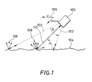
- Fig. 1 are the arrangement of an ultrasonic transducer and the emitted or reflected signals are shown.
- the ultrasonic transducer 100 has a broad radiation characteristic with an opening angle ⁇ .
- the converter 100 sends ultrasonic signals 102 in the area of its opening angle ⁇ off. These emitted signals 102 hit one rough surface 104 and are reflected on it. Dependent from the angular adjustment of the converter the emitted signals 102 at an angle a surface 104.
- the signals 102 striking the rough surface 104 are reflected on this. It is about a diffuse reflection of the signal on surface 104, as shown by reference numeral 108. On Portion 110 of the reflected signals is from converter 100 receive.
- the converter 100 be sufficiently wide Has sensitivity characteristic, that is, the half the opening angle ⁇ / 2 of the transducer is greater than that Irradiation angle ⁇ , so that the diffuse reflection of Signals 102 on the surface of a spectral portion of the Doppler shift Signal exists that from the radiation angle is independent. This is the highest frequency component that occurs in the Doppler spectrum. This frequency component represents is a direct measure of speed.
- the acquisition of the spectral component and the derivation of the speed can be done by a variety of methods become. Such methods include, for example conventional spectral analysis methods or the Fourier transformation on.
- the steps of acquiring the spectral component and deriving the speed comprise a plurality of substeps.
- a first sub-step a lower one Cut-off frequency of a high-pass filter set to a frequency which is greater than the frequency of the radiated Signal 102, and the received signal 110 is replaced by the Filtered high pass filter.
- the next step is the signal power at the output of the high-pass filter is detected and with a predetermined signal power compared.
- the signal power is less than that predetermined signal power, becomes the lower limit frequency of the high-pass filter is lowered by a predetermined value and the steps of filtering, capturing and comparing are repeated.
- the set lower Limit frequency of the high-pass filter output In the event that the signal power is greater than or equal to that is the specified signal power, the set lower Limit frequency of the high-pass filter output, and this is converted into a quantity that represents the speed.
- a fluctuation occurs due to the constant movement of the ski the distance between the transducer 100 and the snow surface on.
- these can Fluctuations after high pass filtering of the received signal 102 by amplifying the filtered signal using a Balanced amplifier with automatic gain control become.
- this is on a Display device displayed.
- the steps of capturing the Spectral component, the derivation of the speed and the Displaying this speed can be done in one place which is spaced from transducer 100.
- the one for speed measurement required data, for example by means of an electromagnetic transmission to a separately arranged unit, which can be found on Wrist or as a head-up display in the skier's helmet located.
- display units can also be used that directly are attached to the ski.
- the detection and discharge device shown in FIG. 2, which are designated in their entirety by reference number 200 is the spectral component with the highest Frequency that exceeds a predetermined energy value, from the Doppler spectrum of the received signal 110 to grasp and the speed from the frequency of the derived spectral component.
- SC filter switched capacitor filter
- This high-pass filter 202 has a lower cut-off frequency f x , which is adjustable.
- the lower limit frequency is set via a voltage-controlled clock oscillator 204, the voltage of which is controlled by a sawtooth voltage generator 206 and a square-wave voltage generator 208.
- the generators 206 and 208 also apply their voltages to a conversion and display unit 210.
- the received signal 110 is applied to the high-pass filter 202 and that present at the output of the high-pass filter 202 Signal is through a low pass filter 212 and a squaring circuit 214 to an input of a comparator circuit 216 created.
- the comparator 216 compares the signal power present at its input with a predetermined signal power. As soon as the applied signal power exceeds the predetermined signal power, the comparator 216 switches and the conversion and display unit 210 converts the limit frequency f x set on the high-pass filter 202 into the speed and displays it.
- the detection and derivation device 200 can additionally a so-called amplifier with automatic gain control include (not shown in Fig. 2), the between the high pass filter 202 and the low pass filter 212 is switched. This amplifier serves fluctuations compensate for the distance between the transducer and the surface, that occur constantly while using a ski.
- Fig. 3 shows a further embodiment of the invention Device in which the received signal 110 was mixed down into the baseband and to a speed dependent Amplifier is applied to the weight received signal depending on the speed. This ensures that the detection and discharge device 200 signals are always created that are in the have essentially the same level.
- the through the Device 200 calculated speed is on the amplifier 300 for weighting the next received signal fed back via a line 302.
- the conversion and display unit 210 described above records the travel times according to a further exemplary embodiment, so that a calculation of the distance traveled is possible. There is also a storage of the maximum speeds and from that a calculation of the average speed possible.
- FIG. 4a shows the front section of a ski 400, the converter 100 is arranged at the tip 402 thereof. Further the opening angle ⁇ of the converter 100 is shown.
- the Transducer 100 can either be placed on top of the ski be so that a hole in the ski must be provided to not to hinder radiation from the transducer 100, or transducer 100 can be located directly on the underside of the ski tip be arranged.
- the acquisition and discharge device 200 can be on the top of the ski tip.
- the detection and derivation device 200 can also be removed be arranged by the converter 100, for example from be carried to the skier.
- Fig. 4b shows another way of attaching the Converter 100.
- converter 100 at the rear 404 of the ski 400 arranged. So that the converter 100 radiate freely can, it must be arranged at the very end of the ski 400. If this arrangement is the ski most of the time in contact with the ground possible because the problem of drifts of the received Signal then does not occur.
- the spectral component is not included the highest frequency that has a given energy value exceeds the basis for calculating the speed, but it is the spectral component with the lowest frequency that has a given energy value exceeds.
- the signal power present at the output of filter 202 is compared with a given signal power. If the signal power is less than the specified one Signal power, the upper cutoff frequency of the Filters 202 increased by a predetermined value and the previous steps are repeated. If the signal power greater than or equal to the specified signal power the set upper limit frequency of the Filters 202 output and converted to a size that represents the speed.
- the present invention not on the use of a high-pass filter or low-pass filter for capturing the spectral components of interest of the Doppler spectrum of the received signal is limited.
- the use of a bandpass filter with one setting the corresponding cut-off frequency or center frequency also possible.
Landscapes
- Engineering & Computer Science (AREA)
- Radar, Positioning & Navigation (AREA)
- Remote Sensing (AREA)
- Physics & Mathematics (AREA)
- General Physics & Mathematics (AREA)
- Computer Networks & Wireless Communication (AREA)
- Acoustics & Sound (AREA)
- Radar Systems Or Details Thereof (AREA)
- Measurement Of Velocity Or Position Using Acoustic Or Ultrasonic Waves (AREA)
- Analysing Materials By The Use Of Radiation (AREA)
Claims (26)
- Procédé de mesure de vitesses sans contact sur des surfaces, en particulier de mesure de vitesses de ski sur des surfaces de neige, aux étapes suivantes consistant à:a) rayonner un signal (102) à une fréquence fixe dans le sens du déplacement (106), suivant un angle de rayonnement (α), l'angle de rayonnement (α) étant inférieur à un demi-angle d'ouverture (/2) d'un dispositif (100) rayonnant ce signal (102);b) recevoir un signal (110) réfléchi à la surface (104) qui est à décalage de Doppler par rapport au signal rayonné (102);c) capter, du spectre Doppler du signal reçu (110), la partie de spectre à la fréquence la plus haute excédant une valeur d'énergie prédéterminée; etd) dériver la vitesse de la fréquence de la partie de spectre captée.
- Procédé suivant la revendication 1, caractérisé par le fait que la saisie de la partie de spectre et la dérivation de la vitesse comprend les étapes suivantes consistant à:c1) régler une fréquence limite inférieure (fx) d'un filtre passe-haut à une fréquence qui est supérieure à la fréquence du signal rayonné (102) ;c2) filtrer passe-haut le signal reçu (110) ;c3) saisir la puissance de signal à la sortie du filtre passe-haut (202) ; etc4) comparer la puissance de signal avec une puissance de signal prédéterminée ;c4.1) si la puissance de signal est inférieure à la puissance de signal prédéterminée :c4.1.1) abaisser d'une valeur prédéterminée la fréquence limite inférieure (fx) du filtre passe-haut (202) ; etc4.1.2) répéter les étapes c2) à c4) ;c4.2 si la puissance de signal est supérieure ou égale à la puissance de signal prédéterminée :c4.2.1) sortir la fréquence limite inférieure (fx) du filtre passe-haut (202) ; etc4.2.2) convertir la fréquence limite inférieure (fx) sortie en une grandeur représentant la vitesse.
- Procédé de mesure de vitesses sans contact sur des surfaces, en particulier de mesure de vitesses de ski sur des surfaces de neige, aux étapes suivantes consistant à:a) rayonner un signal (102) à une fréquence fixe dans le sens contraire au déplacement, suivant un angle de rayonnement (α), l'angle de rayonnement (α) étant inférieur à un demi-angle d'ouverture (/2) d'un dispositif (100) rayonnant ce signal;b) recevoir un signal (110) réfléchi à la surface (104) qui est à décalage Doppler par rapport au signal rayonné (102);c) capter, du spectre Doppler du signal reçu, la partie de spectre à la fréquence la plus basse excédant une valeur d'énergie prédéterminée;d) dériver la vitesse de la fréquence de la partie de spectre captée.
- Procédé suivant la revendication 3, caractérisé par le fait que la saisie de la partie de spectre et la dérivation de la vitesse comprend les étapes suivantes consistant à:c1) régler une fréquence limite inférieure (fx) d'un filtre passe-bas (202) à une fréquence qui est inférieure à la fréquence du signal rayonné (102) ;c2) filtrer passe-bas le signal reçu (110) ;c3) saisir la puissance de signal à la sortie du filtre passe-bas (202) ; etc4) comparer la puissance de signal avec une puissance de signal prédéterminée :c4.1) si la puissance de signal est inférieure à la puissance de signal prédéterminée :c4.1.1) élever d'une valeur prédéterminée la fréquence limite supérieure (fx) du filtre passe-bas (202) ; etc4.1.2) répéter les étapes c2) à c4) ;c4.2 si la puissance de signal est supérieure ou égale à la puissance de signal prédéterminée :c4.2.1) sortir la fréquence limite supérieure (fx) du filtre passe-bas (202) ; etc4.2.2) convertir la fréquence limite supérieure (fx) sortie en une grandeur représentant la vitesse.
- Procédé suivant la revendication 2 ou 4, caractérisé par l'étape de procédé suivant, avant l'étape c2), consistant à :
amplifier le signal reçu à l'aide d'un amplificateur à réglage d'amplification automatique, pour compenser les variations de la distance entre le dispositif (100) rayonnant le signal et la surface (104). - Procédé suivant la revendication 2, 4 ou 5, caractérisé par le fait que le filtre passe-haut (202) ou le filtre passe-has est constitué par un filtre à condensateur de commutation.
- Procédé suivant la revendication 1 ou 3, caractérisé par le fait que l'étape de saisie de la partie de spectre et de la dérivation de la vitesse comprend une transformation de Fourier.
- Procédé suivant l'une des revendications 1 à 7, caractérisé par les étapes de procédé suivantes, avant l'étape c), consistant à :mélanger vers le bas le signal reçu (110) avec la bande de hase ; etpondérer le signal reçu (110) à l'aide d'une amplification fonction de la vitesse (300), de sorte que, pour la saisie de la partie de spectre, des signaux à niveaux sensiblement identiques soient toujours disponibles.
- Procédé suivant l'une des revendications 1 à 8, caractérisé par l'étapes de procédé suivante consistant à :e) afficher la vitesse mesurée sur un dispositif d'affichage (210).
- Procédé suivant la revendication 9, caractérisé par le fait que l'étape e) a lieu à un endroit éloigné du dispositif (100) rayonnant le signal.
- Procédé suivant l'une des revendications 1 à 10, caractérisé par le faitque le signal rayonné (102) est un signal ultrasonore ; etque le dispositif (100) rayonnant le signal est un convertisseur d'ultra-sons.
- Dispositif de mesure de vitesses sans contact sur des surfaces, en particulier de mesure de vitesses de ski sur des surfaces de neige, caractérisé parun dispositif (100) destiné à rayonner un signal (102) à fréquence fixe dans le sens du déplacement, suivant un angle de rayonnement (α), et à capter un signal (110) à décalage Doppler réfléchi à la surface (104), l'angle de rayonnement (α) étant inférieur à un demi-angle d'ouverture (/2) du dispositif (100);un dispositif (200) destiné à capter, du spectre Doppler du signal reçu (110), la partie de spectre à la fréquence la plus haute excédant une valeur d'énergie prédéterminée; etun dispositif destiné à dériver la vitesse de la fréquence de la partie de spectre captée.
- Dispositif suivant la revendication 12, caractérisé par le fait que le dispositif de saisie et de dérivation (200) présente les caractéristiques suivantes:un filtre passe-haut (202) dont la fréquence limite inférieure (fx) est réglable et auquel peut être appliqué le signal reçu (110), la fréquence limite (fx) pouvant être abaissée, commençant par la fréquence limite (fx) qui est supérieure à la fréquence du signal rayonné (102), jusqu'à ce qu'une puissance de signal présente à la sortie du filtre passe-haut (202) excède une puissance de signal prédéterminée;un comparateur (216) qui compare la puissance de signal à la puissance de signal prédéterminée;un dispositif convertisseur (210) destiné à convertir en une vitesse une fréquence à laquelle la puissance de signal à la sortie du filtre passe-haut excède la puissance de signal prédéterminée; etun dispositif d'affichage (210) destiné à afficher la vitesse.
- Dispositif de mesure de vitesses sans contact sur des surfaces, en particulier de mesure de vitesses de ski sur des surfaces de neige, caractérisé parun dispositif (100) destiné à rayonner un signal (102) à fréquence fixe dans le sens contraire au déplacement, suivant un angle de rayonnement (α), et à recevoir un signal (110) à décalage Doppler réfléchi à la surface (104), l'angle de rayonnement (α) étant inférieur à un demi-angle d'ouverture (/2) du dispositif (100);un dispositif (200) destiné à capter, du spectre Doppler du signal reçu (110), la partie de spectre à la fréquence la plus basse excédant une valeur d'énergie prédéterminée; etun dispositif destiné à dériver la vitesse de la fréquence de la partie de spectre captée.
- Dispositif suivant la revendication 14, caractérisé par le fait que le dispositif de saisie et de dérivation (200) présente les caractéristiques suivantes:un filtre passe-bas (202) dont la fréquence limite supérieure (fx) est réglable et auquel peut être appliqué le signal reçu (110), la fréquence limite (fx) pouvant être incrémentée, commençant par la fréquence limite (fx) qui est inférieure à la fréquence du signal rayonné (102), jusqu'à ce qu'une puissance de signal présente à la sortie du filtre passe-bas (202) excède une puissance de signal prédéterminée;un comparateur (216) qui compare la puissance de signal à la puissance de signal prédéterminée;un dispositif convertisseur (210) destiné à convertir en la vitesse une fréquence à laquelle la puissance de signal à la sortie du filtre passe-bas excède la puissance de signal prédéterminée; etun dispositif d'affichage (210) destiné à afficher la vitesse.
- Dispositif suivant la revendication 13 ou 15, caractérisé par le fait quela fréquence limite (fx) du filtre passe-haut (202) ou du filtre passe-bas peut être réglée par un oscillateur rythmé (204) commandé par la tension et réglable par l'intermédiaire d'un générateur de tension en dents de scie (206) et d'un générateur de tension rectangulaire (208), les générateurs (206, 208) étant reliés à l'unité (210);entre le filtre passe-haut (202) ou le filtre passe-bas et le comparateur (202) sont connectés un filtre passe-bas (212) et un circuit limiteur symétrique (214).
- Dispositif suivant la revendication 13, 15 ou 16, caractérisé par le fait que la sortie du filtre passe-haut (202) est reliée à l'entrée d'un amplificateur à réglage d'amplification automatique compensant les variations de la distance entre le dispositif de rayonnement (100) et la surface (104).
- Dispositif suivant la revendication 13, 15, 16 ou 17, caractérisé par le fait que le filtre passe-haut (202) ou le filtre passe-bas est constitué par un filtre à condensateur de commutation.
- Dispositif suivant la revendication 12 ou 14, caractérisé par le fait que le dispositif destiné à saisir les parties de spectre (200) effectue une transformation de Fourier.
- Dispositif suivant l'une des revendications 12 à 19, caractérisé parun dispositif de mélange vers le bas destiné à mélanger le signal reçu (110) dans la bande de base; etun amplificateur (300) fonction de la vitesse destiné à pondérer le signal reçu (110) de sorte qu'à l'entrée du dispositif (200) sont toujours présents des signaux à niveaux sensiblement identiques;le dispositif de mélange vers le bas et l'amplificateur (300) fonction de la vitesse étant connectés entre le dispositif de rayonnement et le dispositif (200).
- Dispositif suivant l'une des revendications 12 à 20, caractérisé par le fait que le dispositif de rayonnement (100) et le dispositif (200) de saisie de la partie de spectre ainsi que le dispositif de dérivation de la vitesse sont distants dans l'espace l'un de l'autre.
- Dispositif suivant l'une des revendications 12 à 21, caractérisé par le faitque le dispositif de rayonnement (100) est un convertisseur d'ultra-sons; etque le signal rayonné (102) est un signal ultrasonore.
- Dispositif suivant l'une des revendications 12 à 22, caractérisé par le fait que le dispositif de réception et de dérivation (200) permet un calcul de la distance parcourue, une mémorisation des vitesses maximales, un calcul de la vitesse moyenne, ainsi qu'une mesure du temps de déplacement.
- Ski (400) présentant un dispositif suivant l'une des revendications 12 ou 13 et 16 à 23, avec renvoi à la revendication 11 ou 12, caractérisé par le faitque le dispositif de rayonnement (100) est disposé près de la pointe du ski (402), sur la face supérieure du ski, dans la pointe du ski étant prévu un évidement permettant le rayonnement et la réception de signaux en direction de la surface de neige; etque le dispositif de réception et de dérivation (200) est disposé sur le ski (400), distant du dispositif de rayonnement (100), ou peut être porté par un utilisateur du ski.
- Ski (400) présentant un dispositif suivant l'une des revendications 12 ou 13 et 16 à 23, avec renvoi à la revendication 12 ou 13, caractérisé par le faitque le dispositif de rayonnement (100) est disposé prés de la pointe du ski (402), sur la face inférieure de celui-ci; etque le dispositif de réception et de dérivation (200) est disposé sur le ski (400), distant du dispositif de rayonnement (100), ou peut être porté par un utilisateur du ski.
- Ski (400) présentant un dispositif suivant l'une des revendications 14 ou 15 et 16 à 23, avec renvoi à la revendication 14 ou 15, caractérisé par le faitque le dispositif de rayonnement (100) est disposé sur la face supérieure du ski (400), à l'extrémité arrière de celui-ci; etque le dispositif de réception et de dérivation (200) est disposé sur le ski (400), distant du dispositif de rayonnement (100), ou peut être porté par un utilisateur du ski.
Applications Claiming Priority (3)
| Application Number | Priority Date | Filing Date | Title |
|---|---|---|---|
| DE19501228 | 1995-01-17 | ||
| DE19501228A DE19501228C2 (de) | 1995-01-17 | 1995-01-17 | Verfahren und Vorrichtung zur berührungslosen Geschwindigkeitsmessung auf Oberflächen |
| PCT/EP1995/004172 WO1996022549A1 (fr) | 1995-01-17 | 1995-10-24 | Procede et dispositif de mesure de vitesses sans contact sur des surfaces |
Publications (3)
| Publication Number | Publication Date |
|---|---|
| EP0804745A1 EP0804745A1 (fr) | 1997-11-05 |
| EP0804745B1 true EP0804745B1 (fr) | 2000-01-26 |
| EP0804745B2 EP0804745B2 (fr) | 2007-11-14 |
Family
ID=7751664
Family Applications (1)
| Application Number | Title | Priority Date | Filing Date |
|---|---|---|---|
| EP95937837A Expired - Lifetime EP0804745B2 (fr) | 1995-01-17 | 1995-10-24 | Procede et dispositif de mesure de vitesses sans contact sur des surfaces |
Country Status (4)
| Country | Link |
|---|---|
| EP (1) | EP0804745B2 (fr) |
| AT (1) | ATE189314T1 (fr) |
| DE (2) | DE19501228C2 (fr) |
| WO (1) | WO1996022549A1 (fr) |
Families Citing this family (2)
| Publication number | Priority date | Publication date | Assignee | Title |
|---|---|---|---|---|
| GB9726719D0 (en) * | 1997-12-18 | 1998-02-18 | Bolton School | A ski speedometer |
| DE19914486C1 (de) | 1999-03-30 | 2000-05-18 | Fraunhofer Ges Forschung | Vorrichtung und Verfahren zur berührungslosen Geschwindigkeitsmessung auf Oberflächen |
Family Cites Families (4)
| Publication number | Priority date | Publication date | Assignee | Title |
|---|---|---|---|---|
| US4231039A (en) * | 1978-12-28 | 1980-10-28 | Glymar | Radar speedometer |
| US4660050A (en) * | 1983-04-06 | 1987-04-21 | Trw Inc. | Doppler radar velocity measurement horn |
| US4757714A (en) * | 1986-09-25 | 1988-07-19 | Insight, Inc. | Speed sensor and head-mounted data display |
| GB2276055B (en) † | 1993-03-12 | 1997-02-19 | Univ York | Speed measurement |
-
1995
- 1995-01-17 DE DE19501228A patent/DE19501228C2/de not_active Expired - Lifetime
- 1995-10-24 DE DE59507715T patent/DE59507715D1/de not_active Expired - Lifetime
- 1995-10-24 WO PCT/EP1995/004172 patent/WO1996022549A1/fr not_active Ceased
- 1995-10-24 AT AT95937837T patent/ATE189314T1/de active
- 1995-10-24 EP EP95937837A patent/EP0804745B2/fr not_active Expired - Lifetime
Also Published As
| Publication number | Publication date |
|---|---|
| ATE189314T1 (de) | 2000-02-15 |
| DE19501228A1 (de) | 1996-08-01 |
| EP0804745B2 (fr) | 2007-11-14 |
| EP0804745A1 (fr) | 1997-11-05 |
| WO1996022549A1 (fr) | 1996-07-25 |
| DE19501228C2 (de) | 1997-02-20 |
| DE59507715D1 (de) | 2000-03-02 |
Similar Documents
| Publication | Publication Date | Title |
|---|---|---|
| DE3204874C2 (de) | Passives Verfahren zum Gewinnen von Zieldaten von einer Schallquelle | |
| DE102005063628B4 (de) | Radarvorrichtung | |
| DE112013004908B4 (de) | Objekterfassungsvorrichtung | |
| DE69114753T2 (de) | Optisches Fehlersuchgerät mit adaptiver Pulslänge. | |
| AT508562B1 (de) | 3-d vermessungseinrichtung | |
| DE60306559T2 (de) | Verfahren und Vorrichtung zur Bestimmung von Luftturbulenz mittels bistatischen Messungen | |
| EP0775321B1 (fr) | Indicateur de vitesse | |
| DE69117792T2 (de) | Optischer Detektor von Fehlern | |
| DE102018220001B4 (de) | Objekterfassungsvorrichtung | |
| DE19928915A1 (de) | Verfahren zur Sichtweitenbestimmung | |
| DE202006021074U1 (de) | Bestimmung von Eigendrehimpulsparametern von einem Sportball | |
| EP1380854A2 (fr) | Procédé et système radar de détermination d'angles de direction d'objets radar | |
| EP0204295A2 (fr) | Dispositif de mesure de la direction et de la vitesse du vent dans l'atmosphère | |
| DE3940404A1 (de) | Verfahren und geraet zur dopplereffekt-geschwindigkeitsmessung | |
| DE102021002239A1 (de) | Doppler Lidar zur Erfassung von Wind- und/oder Wirbelsituationen | |
| DE60225642T2 (de) | Verfahren zur Bestimmung des Azimuts eines Zieles mittels eines ASR-Radars | |
| EP0635731B1 (fr) | Méthode et capteur pour déterminer la limite de visibilité dans le brouillard épais | |
| EP1084422B1 (fr) | Dispositif et procede pour mesurer une vitesse sans contact sur des surfaces | |
| DD229481A5 (de) | Verfahren zur entfernungsmessung und entfernungsmesser zur durchfuehrung des verfahrens | |
| DE19962949A1 (de) | Vorrichtung zur abtaststrahlungsbasierten Oberflächenzustandserkennung insbesondere von Straßen | |
| DE2706309C2 (de) | Anordnung zur Messung der Wolkenhöhe | |
| EP0804745B1 (fr) | Procede et dispositif de mesure de vitesses sans contact sur des surfaces | |
| DE202008018045U1 (de) | Impulslaserstrahldetektor mit verbesserter Sonnen- und Temperaturkompensation | |
| DE3203788A1 (de) | Vorrichtung in einem entfernungsmesssystem | |
| DE60112809T2 (de) | Verfahren zur messung der point-blank-kontrollpunktzeit eines flugzeugs |
Legal Events
| Date | Code | Title | Description |
|---|---|---|---|
| PUAI | Public reference made under article 153(3) epc to a published international application that has entered the european phase |
Free format text: ORIGINAL CODE: 0009012 |
|
| 17P | Request for examination filed |
Effective date: 19970128 |
|
| AK | Designated contracting states |
Kind code of ref document: A1 Designated state(s): AT CH DE FR GB IT LI NL SE |
|
| GRAG | Despatch of communication of intention to grant |
Free format text: ORIGINAL CODE: EPIDOS AGRA |
|
| GRAG | Despatch of communication of intention to grant |
Free format text: ORIGINAL CODE: EPIDOS AGRA |
|
| GRAH | Despatch of communication of intention to grant a patent |
Free format text: ORIGINAL CODE: EPIDOS IGRA |
|
| 17Q | First examination report despatched |
Effective date: 19990112 |
|
| GRAH | Despatch of communication of intention to grant a patent |
Free format text: ORIGINAL CODE: EPIDOS IGRA |
|
| GRAA | (expected) grant |
Free format text: ORIGINAL CODE: 0009210 |
|
| ITF | It: translation for a ep patent filed | ||
| AK | Designated contracting states |
Kind code of ref document: B1 Designated state(s): AT CH DE FR GB IT LI NL SE |
|
| REF | Corresponds to: |
Ref document number: 189314 Country of ref document: AT Date of ref document: 20000215 Kind code of ref document: T |
|
| REG | Reference to a national code |
Ref country code: CH Ref legal event code: EP |
|
| ET | Fr: translation filed | ||
| REF | Corresponds to: |
Ref document number: 59507715 Country of ref document: DE Date of ref document: 20000302 |
|
| GBT | Gb: translation of ep patent filed (gb section 77(6)(a)/1977) |
Effective date: 20000320 |
|
| PLBQ | Unpublished change to opponent data |
Free format text: ORIGINAL CODE: EPIDOS OPPO |
|
| PLBI | Opposition filed |
Free format text: ORIGINAL CODE: 0009260 |
|
| PLBF | Reply of patent proprietor to notice(s) of opposition |
Free format text: ORIGINAL CODE: EPIDOS OBSO |
|
| 26 | Opposition filed |
Opponent name: SPORTS INSTRUMENTS USA, INC., Effective date: 20001023 |
|
| NLR1 | Nl: opposition has been filed with the epo |
Opponent name: SPORTS INSTRUMENTS USA, INC., |
|
| PLBF | Reply of patent proprietor to notice(s) of opposition |
Free format text: ORIGINAL CODE: EPIDOS OBSO |
|
| PLBF | Reply of patent proprietor to notice(s) of opposition |
Free format text: ORIGINAL CODE: EPIDOS OBSO |
|
| REG | Reference to a national code |
Ref country code: GB Ref legal event code: IF02 |
|
| RAP2 | Party data changed (patent owner data changed or rights of a patent transferred) |
Owner name: FRAUNHOFER-GESELLSCHAFT ZUR FOERDERUNG DERANGEWAND |
|
| NLT2 | Nl: modifications (of names), taken from the european patent patent bulletin |
Owner name: FRAUNHOFER-GESELLSCHAFT ZUR FOERDERUNG DER |
|
| REG | Reference to a national code |
Ref country code: CH Ref legal event code: PFA Owner name: FRAUNHOFER-GESELLSCHAFT ZUR FOERDERUNG DER ANGEWA Free format text: FRAUNHOFER-GESELLSCHAFT ZUR FOERDERUNG DER ANGEWANDTEN FORSCHUNG E.V.#LEONRODSTRASSE 54#80636 MUENCHEN (DE) -TRANSFER TO- FRAUNHOFER-GESELLSCHAFT ZUR FOERDERUNG DER ANGEWANDTEN FORSCHUNG E.V.#HANSASTRASSE 27 C#80686 MUENCHEN (DE) |
|
| PLAY | Examination report in opposition despatched + time limit |
Free format text: ORIGINAL CODE: EPIDOSNORE2 |
|
| PLBC | Reply to examination report in opposition received |
Free format text: ORIGINAL CODE: EPIDOSNORE3 |
|
| PLAY | Examination report in opposition despatched + time limit |
Free format text: ORIGINAL CODE: EPIDOSNORE2 |
|
| PLBC | Reply to examination report in opposition received |
Free format text: ORIGINAL CODE: EPIDOSNORE3 |
|
| PLAY | Examination report in opposition despatched + time limit |
Free format text: ORIGINAL CODE: EPIDOSNORE2 |
|
| RAP2 | Party data changed (patent owner data changed or rights of a patent transferred) |
Owner name: FRAUNHOFER-GESELLSCHAFT ZUR FOERDERUNG DER ANGEWAN |
|
| NLT2 | Nl: modifications (of names), taken from the european patent patent bulletin |
Owner name: FRAUNHOFER-GESELLSCHAFT ZUR Effective date: 20070117 |
|
| PUAH | Patent maintained in amended form |
Free format text: ORIGINAL CODE: 0009272 |
|
| STAA | Information on the status of an ep patent application or granted ep patent |
Free format text: STATUS: PATENT MAINTAINED AS AMENDED |
|
| 27A | Patent maintained in amended form |
Effective date: 20071114 |
|
| AK | Designated contracting states |
Kind code of ref document: B2 Designated state(s): AT CH DE FR GB IT LI NL SE |
|
| REG | Reference to a national code |
Ref country code: SE Ref legal event code: RPEO |
|
| REG | Reference to a national code |
Ref country code: CH Ref legal event code: AEN Free format text: AUFRECHTERHALTUNG DES PATENTES IN GEAENDERTER FORM |
|
| NLR2 | Nl: decision of opposition |
Effective date: 20071114 |
|
| NLR3 | Nl: receipt of modified translations in the netherlands language after an opposition procedure | ||
| GBTA | Gb: translation of amended ep patent filed (gb section 77(6)(b)/1977) | ||
| ET3 | Fr: translation filed ** decision concerning opposition | ||
| PGFP | Annual fee paid to national office [announced via postgrant information from national office to epo] |
Ref country code: CH Payment date: 20141024 Year of fee payment: 20 Ref country code: DE Payment date: 20141024 Year of fee payment: 20 Ref country code: FR Payment date: 20141021 Year of fee payment: 20 Ref country code: GB Payment date: 20141024 Year of fee payment: 20 Ref country code: SE Payment date: 20141024 Year of fee payment: 20 |
|
| PGFP | Annual fee paid to national office [announced via postgrant information from national office to epo] |
Ref country code: AT Payment date: 20141022 Year of fee payment: 20 Ref country code: NL Payment date: 20141023 Year of fee payment: 20 |
|
| PGFP | Annual fee paid to national office [announced via postgrant information from national office to epo] |
Ref country code: IT Payment date: 20141023 Year of fee payment: 20 |
|
| REG | Reference to a national code |
Ref country code: DE Ref legal event code: R071 Ref document number: 59507715 Country of ref document: DE |
|
| REG | Reference to a national code |
Ref country code: NL Ref legal event code: MK Effective date: 20151023 |
|
| REG | Reference to a national code |
Ref country code: CH Ref legal event code: PL |
|
| REG | Reference to a national code |
Ref country code: GB Ref legal event code: PE20 Expiry date: 20151023 |
|
| REG | Reference to a national code |
Ref country code: AT Ref legal event code: MK07 Ref document number: 189314 Country of ref document: AT Kind code of ref document: T Effective date: 20151024 Ref country code: SE Ref legal event code: EUG |
|
| PG25 | Lapsed in a contracting state [announced via postgrant information from national office to epo] |
Ref country code: GB Free format text: LAPSE BECAUSE OF EXPIRATION OF PROTECTION Effective date: 20151023 |