EP0803887A2 - Clavier a membrane - Google Patents
Clavier a membrane Download PDFInfo
- Publication number
- EP0803887A2 EP0803887A2 EP97106685A EP97106685A EP0803887A2 EP 0803887 A2 EP0803887 A2 EP 0803887A2 EP 97106685 A EP97106685 A EP 97106685A EP 97106685 A EP97106685 A EP 97106685A EP 0803887 A2 EP0803887 A2 EP 0803887A2
- Authority
- EP
- European Patent Office
- Prior art keywords
- front panel
- membrane keyboard
- technology
- keyboard
- membrane
- Prior art date
- Legal status (The legal status is an assumption and is not a legal conclusion. Google has not performed a legal analysis and makes no representation as to the accuracy of the status listed.)
- Withdrawn
Links
Images
Classifications
-
- H—ELECTRICITY
- H01—ELECTRIC ELEMENTS
- H01H—ELECTRIC SWITCHES; RELAYS; SELECTORS; EMERGENCY PROTECTIVE DEVICES
- H01H13/00—Switches having rectilinearly-movable operating part or parts adapted for pushing or pulling in one direction only, e.g. push-button switch
- H01H13/70—Switches having rectilinearly-movable operating part or parts adapted for pushing or pulling in one direction only, e.g. push-button switch having a plurality of operating members associated with different sets of contacts, e.g. keyboard
- H01H13/7006—Switches having rectilinearly-movable operating part or parts adapted for pushing or pulling in one direction only, e.g. push-button switch having a plurality of operating members associated with different sets of contacts, e.g. keyboard comprising a separate movable contact element for each switch site, all other elements being integrated in layers
-
- H—ELECTRICITY
- H01—ELECTRIC ELEMENTS
- H01H—ELECTRIC SWITCHES; RELAYS; SELECTORS; EMERGENCY PROTECTIVE DEVICES
- H01H2207/00—Connections
- H01H2207/022—Plug
-
- H—ELECTRICITY
- H01—ELECTRIC ELEMENTS
- H01H—ELECTRIC SWITCHES; RELAYS; SELECTORS; EMERGENCY PROTECTIVE DEVICES
- H01H2207/00—Connections
- H01H2207/032—Surface mounted component
-
- H—ELECTRICITY
- H01—ELECTRIC ELEMENTS
- H01H—ELECTRIC SWITCHES; RELAYS; SELECTORS; EMERGENCY PROTECTIVE DEVICES
- H01H2219/00—Legends
- H01H2219/002—Legends replaceable; adaptable
- H01H2219/014—LED
-
- H—ELECTRICITY
- H01—ELECTRIC ELEMENTS
- H01H—ELECTRIC SWITCHES; RELAYS; SELECTORS; EMERGENCY PROTECTIVE DEVICES
- H01H2219/00—Legends
- H01H2219/036—Light emitting elements
- H01H2219/04—Attachments; Connections
-
- H—ELECTRICITY
- H01—ELECTRIC ELEMENTS
- H01H—ELECTRIC SWITCHES; RELAYS; SELECTORS; EMERGENCY PROTECTIVE DEVICES
- H01H2223/00—Casings
- H01H2223/044—Protecting cover
-
- H—ELECTRICITY
- H01—ELECTRIC ELEMENTS
- H01H—ELECTRIC SWITCHES; RELAYS; SELECTORS; EMERGENCY PROTECTIVE DEVICES
- H01H2239/00—Miscellaneous
- H01H2239/01—Miscellaneous combined with other elements on the same substrate
-
- H—ELECTRICITY
- H05—ELECTRIC TECHNIQUES NOT OTHERWISE PROVIDED FOR
- H05K—PRINTED CIRCUITS; CASINGS OR CONSTRUCTIONAL DETAILS OF ELECTRIC APPARATUS; MANUFACTURE OF ASSEMBLAGES OF ELECTRICAL COMPONENTS
- H05K1/00—Printed circuits
- H05K1/18—Printed circuits structurally associated with non-printed electric components
Definitions
- the invention is based on a membrane keyboard.
- Membrane keyboards are devices that are used in particular in an industrial environment, i.e. in an environment that is not dust-free or dirt-free.
- Membrane keyboards contain operating elements which are operated by pressure or touch, and optionally display means, which can be, for example, transparent or translucent fields, behind which light-emitting diodes, displays or the like are arranged.
- the known membrane keyboards contain a front panel, which generally consists of aluminum and on the front of which the operating elements are arranged.
- a printed circuit board is then arranged behind the windscreen, on which the electronic elements are present which are necessary for controlling the keyboard and for evaluating keyboard information.
- the power supply elements, a power supply unit or the like are then arranged on yet another plate fastened with spacers.
- the invention has for its object to provide a membrane keyboard that is very easy to manufacture and assemble and that requires a small depth.
- the invention proposes a membrane keyboard with the features listed in claim 1. Developments of the invention are the subject of dependent claims.
- the components to be arranged on the back of the membrane keyboard can be purely electronic components, e.g. B. circuits, act, or also plugs, power strips, sockets for boards or the like. According to the invention, all the electronic components required for the keyboard are attached directly behind the front panel to this. The attachment can be done for example in SMD technology, which is a common method for attaching small electronic components.
- Plugs, power strips or other components that are not soldered, but are mechanically connected to the front panel, are attached according to the invention using press-fit technology. This means that they are pressed into through holes or blind holes in the front panel so that they do not protrude from the front of the front panel. A cover film is applied there, which, with the exception of the cracked frogs, should fit smoothly.
- the front panel is no longer made of aluminum, but is designed as a printed circuit board.
- the purely mechanical components required to attach the front panel to a device can also be attached to the front panel using press-fit technology. This can be, for example, distance towers or the like.
- the power supply takes place on a separate plate which is connected to the front plate via mechanical spacer elements, for example spacer towers.
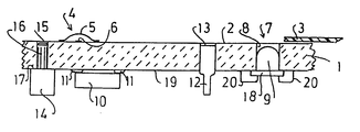
- a partial section through a membrane keyboard is shown, in which the front panel 1 receiving the membrane keyboard is designed as a printed circuit board.
- the upper side 2 of the front plate 1 in the figure forms the side facing the user. It is designed as a flat surface without projections and is covered in the finished state by a foil 3, which is only indicated.
- Control elements 4 are attached to the flat front side 2 of the circuit board 1, as in the example shown, a snap frog 5. It is a bendable metal part that only protrudes slightly above the surface and can be brought into contact with the contact element 6 underneath by pressing.
- the crack frogs 5 are also under the film 3.
- the front panel contains a display means 7 which is formed by a light-emitting diode 9 arranged in a through opening 8.
- the film 3 has a window in this area, which can be transparent or translucent.
- the membrane keyboard is intended to trigger certain processes by actuating an actuating element 4. This is usually done in that key presses are coded in an associated electronics, so that a signal encoded in a certain way is then available as output.
- the electronic components belonging to this evaluation and control electronics are represented in the simplified representation of the figure by a single electronic component 10.
- This electronic component 10 is an integrated circuit in SMD design, which is soldered directly onto soldering points 11 on the rear side of the front panel 1 using SMD technology.
- auxiliary elements such as a connector pin 12 can be arranged on the rear of the front panel 1, which are connected to the front panel 1 using press-fit technology. This means that the component is pressed into a hole 13 in the front plate 1, the press-in simultaneously producing a mechanical fixation and, if necessary, contacting the contacted walls of the hole 13.
- the connector pin 12 is only given here as a possible component.
- Spacer towers 14 which therefore take on a purely mechanical function, are used for mechanical attachment to a further plate (not shown in the figure) which receives the power supply.
- the spacer tower 14 is pressed similarly to the plug pin 12 in a hole 15 of the circuit board 1.
- it contains a cylindrical lug 16 which corresponds to the diameter of the hole 15.
- the lug 16 has a reduced diameter compared to the other spacing tower 14, so that an abutment shoulder 17 is formed. This contact shoulder 17 limits the penetration movement of the attachment 16 into the printed circuit board caused by the pressing.
- the approach 16 is matched to the circuit board 1 so that its free end does not protrude beyond the front 2 of the circuit board 1.
- the light-emitting diode 9 is also arranged, which has a flange-like edge 18 with which it bears against the rear side 19 of the front plate 1. Since no forces are exerted on the light-emitting diode 9, it does not need to be pressed in, but only lies in the hole 8. It can be fastened solely on the basis of the two lead wires 20.
- the membrane keyboard proposed by the invention can be produced very easily since the front panel can be equipped like a conventional printed circuit board. It also has a shallow depth due to the omission of the intermediate board.
Landscapes
- Push-Button Switches (AREA)
- Input From Keyboards Or The Like (AREA)
Applications Claiming Priority (2)
| Application Number | Priority Date | Filing Date | Title |
|---|---|---|---|
| DE19616451 | 1996-04-25 | ||
| DE1996116451 DE19616451B4 (de) | 1996-04-25 | 1996-04-25 | Folientastatur |
Publications (2)
| Publication Number | Publication Date |
|---|---|
| EP0803887A2 true EP0803887A2 (fr) | 1997-10-29 |
| EP0803887A3 EP0803887A3 (fr) | 1998-08-05 |
Family
ID=7792366
Family Applications (1)
| Application Number | Title | Priority Date | Filing Date |
|---|---|---|---|
| EP97106685A Withdrawn EP0803887A3 (fr) | 1996-04-25 | 1997-04-23 | Clavier a membrane |
Country Status (2)
| Country | Link |
|---|---|
| EP (1) | EP0803887A3 (fr) |
| DE (1) | DE19616451B4 (fr) |
Families Citing this family (1)
| Publication number | Priority date | Publication date | Assignee | Title |
|---|---|---|---|---|
| DE19924301A1 (de) * | 1999-05-27 | 2000-12-21 | Mekra Lang Gmbh & Co Kg | Steuersystem für elektrisch betriebene Funktionseinheiten in Kraftfahrzeugen |
Family Cites Families (3)
| Publication number | Priority date | Publication date | Assignee | Title |
|---|---|---|---|---|
| DE8619781U1 (de) * | 1986-07-23 | 1987-04-02 | Picker International GmbH, 8000 München | Bedienfeldplatte eines medizinischen Gerätes, insbesondere eines Röntgengenerators |
| DK19593D0 (da) * | 1993-02-22 | 1993-02-22 | Mogens Nicolaisen | Beroeringsfoelsomt betjeningspanel |
| DE29505969U1 (de) * | 1994-10-21 | 1995-06-14 | Celfa Ag, Seewen | Frontfolie für Folientastaturen o.dgl. |
-
1996
- 1996-04-25 DE DE1996116451 patent/DE19616451B4/de not_active Expired - Fee Related
-
1997
- 1997-04-23 EP EP97106685A patent/EP0803887A3/fr not_active Withdrawn
Also Published As
| Publication number | Publication date |
|---|---|
| EP0803887A3 (fr) | 1998-08-05 |
| DE19616451A1 (de) | 1997-10-30 |
| DE19616451B4 (de) | 2005-08-18 |
Similar Documents
| Publication | Publication Date | Title |
|---|---|---|
| EP1134849B1 (fr) | Jeu de pièces d'éclairage pour l'éclairage, l'affichage ou la signalisation et connecteur électrique pour un tel jeu de pièces | |
| EP1484950A2 (fr) | Méthode de mise en contact èlectrique | |
| DE2635888A1 (de) | Tastenfeld zur betaetigung elektrischer geraete | |
| DE2245415C3 (de) | Kompakter elektronischer Rechner | |
| DE9411392U1 (de) | Elektro-Installationsgerät | |
| EP3663494B1 (fr) | Serrure de porte de voiture automobile | |
| DE3710394C3 (de) | Elektrische Anschlußklemme für Leiterplatten | |
| DE3812635A1 (de) | Einrichtung mit einem traeger und mindestens einer ein gehaeuse sowie ein piezoelektrisches element aufweisenden, elektrischen schaltvorrichtung | |
| DE3116410A1 (de) | Elektronische baueinheit | |
| DE19616451B4 (de) | Folientastatur | |
| EP0799406A1 (fr) | Indicateur | |
| DE4332927C2 (de) | Piezo-Schaltelement | |
| DE3801352C2 (fr) | ||
| DE2746564C3 (de) | Zeitmeßgerät mit Anzeigezelle und Drucktasten | |
| DE69501604T2 (de) | Kollektoranschluss zur Kontaktierung einer Batterie zur Energieversorgung einer elektronischen Schaltung, elektronische Schaltung und Fernbedienung mit einer derartigen Schaltung | |
| EP1491077B2 (fr) | Appareil de commande | |
| EP1562296A2 (fr) | Appareil électronique à monter dans une automobile | |
| CH681336A5 (fr) | ||
| DE9205228U1 (de) | Folientastatur | |
| DE9411391U1 (de) | Elektro-Installationsgerät | |
| DE10314539B4 (de) | Modular aufgebautes Befehlsgerät | |
| DE19941251A1 (de) | Durchsichtige elektrische Funktionsscheibe | |
| EP2048782B1 (fr) | Dispositif de commutation actionnable pour un véhicule automobile | |
| EP0201572B1 (fr) | Clavier pour interrupteurs ou objet similaire | |
| DE102008058950A1 (de) | Tastenfeld sowie Tastenfeldmodul |
Legal Events
| Date | Code | Title | Description |
|---|---|---|---|
| PUAI | Public reference made under article 153(3) epc to a published international application that has entered the european phase |
Free format text: ORIGINAL CODE: 0009012 |
|
| AK | Designated contracting states |
Kind code of ref document: A2 Designated state(s): AT CH DE FR GB IT LI |
|
| PUAL | Search report despatched |
Free format text: ORIGINAL CODE: 0009013 |
|
| AK | Designated contracting states |
Kind code of ref document: A3 Designated state(s): AT CH DE FR GB IT LI |
|
| STAA | Information on the status of an ep patent application or granted ep patent |
Free format text: STATUS: THE APPLICATION IS DEEMED TO BE WITHDRAWN |
|
| 18D | Application deemed to be withdrawn |
Effective date: 19990206 |