EP0803881A1 - Hochspannungsstrombegrenzer auf Polymerbasis - Google Patents
Hochspannungsstrombegrenzer auf Polymerbasis Download PDFInfo
- Publication number
- EP0803881A1 EP0803881A1 EP97400880A EP97400880A EP0803881A1 EP 0803881 A1 EP0803881 A1 EP 0803881A1 EP 97400880 A EP97400880 A EP 97400880A EP 97400880 A EP97400880 A EP 97400880A EP 0803881 A1 EP0803881 A1 EP 0803881A1
- Authority
- EP
- European Patent Office
- Prior art keywords
- elements
- matrix
- limiter according
- polymer
- conductors
- Prior art date
- Legal status (The legal status is an assumption and is not a legal conclusion. Google has not performed a legal analysis and makes no representation as to the accuracy of the status listed.)
- Granted
Links
Images

Classifications
-
- H—ELECTRICITY
- H01—ELECTRIC ELEMENTS
- H01C—RESISTORS
- H01C7/00—Non-adjustable resistors formed as one or more layers or coatings; Non-adjustable resistors made from powdered conducting material or powdered semi-conducting material with or without insulating material
- H01C7/13—Non-adjustable resistors formed as one or more layers or coatings; Non-adjustable resistors made from powdered conducting material or powdered semi-conducting material with or without insulating material current responsive
Definitions
- the present invention relates to a high voltage polymer current limiter.
- a polymer current limiter comprising at least one stack of several stages of elements of linear resistance and of elements with variable resistance of polymer, characterized in that each stage is constituted by a linear resistance in the form of a disc around which the polymer elements in the form of a pellet are connected in parallel, the transverse axes of the said pellet being perpendicular to the axis of the stack.
- the polymer elements small in size and especially thin, have metal tabs welded on each of their faces and the end of which is welded to a collector.
- This device which requires a large number of welds or electrical connections, is not very economical and is not sufficiently robust.
- each element has a relatively high own capacity. This results in a large capacity per stage, which results in a possibility of unbalancing the voltage distribution between the stages.
- An object of the present invention is to design a polymer current limiter having a robust structure, requiring only a very small number of soldering or electrical connections, and having a low overall capacity.
- the subject of the invention is a high voltage polymer current limiter comprising, per phase, a fast circuit breaker pole, a semi-fast protection circuit breaker pole and a set of elements based on polymer of very low resistivity loaded with black. of carbon mounted in series and in parallel, characterized in that the elements comprise a matrix of polymer charged with carbon having an elongated shape and having inside it two parallel metallic conductors.
- the matrix has an oblong section.
- the matrix is surrounded by a sheath of insulating material.
- the sheath material is a fluoropolymer.
- the two conductors of an element open out at the same end out of the matrix and a group of elements in series is constituted by an assembly of elements arranged side by side and in contact two by two by the short side of their lateral surface, and connected by connections arranged on the same side of the assembly.
- the two conductors of an element open out of the matrix respectively at opposite ends and that a group of elements in series is constituted by an assembly of elements arranged side by side. side by side and in pairs contact by the long side of their lateral surface and connected by connections arranged alternately on either side of the assembly.
- the electrical resistivity of the polymer charged with carbon black is approximately 1 ⁇ xcm.
- the length of an element is of the order of 1000 mm.
- the distance between the parallel conductors of an element is of the order of 10 mm.
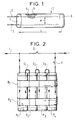
- reference 1 designates a polymer element used in the production of the limiter of the invention.
- This element comprises two parallel conductors, 2 and 3, preferably made of tinned copper, in the form of a braid or rod.
- These conductors are coated in a matrix 4 of polymer (polyethylene) loaded with carbon black; the matrix is protected by an insulating sheath 5, for example of fluoropolymer, ensuring good mechanical and dielectric strength; the matrix is closed at its two ends by insulating plugs 6 and 7.
- the conductors have, inside the matrix, a length L and are separated by a distance e. At one end of the element, the conductors 2 and 3 pass through the end plug (the plug 7 in Fig.1).
- the electrical resistivity of the polymer loaded with carbon black is approximately 1 ⁇ xcm for a compound comprising 50% by weight of polymer and 50% by weight of carbon black.
- the matrix has a preferably oblong section, which makes it possible to reduce the size of the device.
- Fig.2 shows a limiter pole according to the invention, inserted on a phase 1 of the line to be protected.
- the limiter pole comprises a fast circuit breaker pole D arranged in series in line l and, in parallel on the terminals of this circuit breaker, an assembly comprising in series a semi-fast circuit breaker d and a plurality of polymer elements of the type described above, connected in series, and referenced P1 to P4.
- the elements are arranged side by side, and in pairs contact by the short side of their insulating surface.
- the elements P1 to P4 are connected in series by metallic connections C1 to C3 which are all on the same side. In the two conductors of the same element, the currents flow in opposite directions.
- All the elements P1 to P4 are rigidly assembled by insulating strips B1, B2.
- the assembly is preferably placed in an insulating enclosure, not shown, filled with a dielectric gas such as nitrogen at atmospheric pressure, and provided with current bushings.
- a limiter for a nominal voltage line at 24 kV will include 20 groups of elements in parallel, each group being made up of twenty polymer elements in series.
- circuit breaker D opens very quickly. The current goes out in the circuit breaker D and drifts in all the elements P1 to P4.
- the current causes very rapid heating (one to two milliseconds for example) of the polymer elements whose ohmic resistance, beyond a certain temperature threshold, for example 110 ° C., increases by a factor of up to 100. This sudden increase in resistance of the group of polymer elements makes it possible to limit the fault current.
- the residual current is cut by the circuit breaker d which opens for example 20 ms after the appearance of the fault.
- Fig. 3 shows how we carry out the paralleling of two groups G1 and G2 of 4 elements P1 to P4 and Q1 to Q4.
- Fig.4 illustrates an alternative embodiment in which the currents in the two conductors of each polymer element are in the same direction. For this, the two conductors of an element open respectively out of the matrix at opposite ends.
- Fig.4 shows an assembly of 4 elements P'1, P'2, P'3, P'4 arranged side by side and in contact two by two by the long side of their lateral surface.
- the connections C'1, C'2, C'3 are not on the same side but alternate.
- the references B'1 and B'2 designate insulating assembly strips.
Landscapes
- Engineering & Computer Science (AREA)
- Microelectronics & Electronic Packaging (AREA)
- Physics & Mathematics (AREA)
- Electromagnetism (AREA)
- Emergency Protection Circuit Devices (AREA)
- Thermistors And Varistors (AREA)
- Polyoxymethylene Polymers And Polymers With Carbon-To-Carbon Bonds (AREA)
- Addition Polymer Or Copolymer, Post-Treatments, Or Chemical Modifications (AREA)
- Push-Button Switches (AREA)
- Cable Accessories (AREA)
Applications Claiming Priority (2)
| Application Number | Priority Date | Filing Date | Title |
|---|---|---|---|
| FR9605304 | 1996-04-26 | ||
| FR9605304A FR2748166B1 (fr) | 1996-04-26 | 1996-04-26 | Limiteur de courant a polymere a haute tension |
Publications (2)
| Publication Number | Publication Date |
|---|---|
| EP0803881A1 true EP0803881A1 (de) | 1997-10-29 |
| EP0803881B1 EP0803881B1 (de) | 1999-08-25 |
Family
ID=9491631
Family Applications (1)
| Application Number | Title | Priority Date | Filing Date |
|---|---|---|---|
| EP97400880A Expired - Lifetime EP0803881B1 (de) | 1996-04-26 | 1997-04-21 | Hochspannungsstrombegrenzer auf Polymerbasis |
Country Status (6)
| Country | Link |
|---|---|
| US (1) | US5977862A (de) |
| EP (1) | EP0803881B1 (de) |
| AT (1) | ATE183849T1 (de) |
| DE (1) | DE69700445T2 (de) |
| ES (1) | ES2135970T3 (de) |
| FR (1) | FR2748166B1 (de) |
Families Citing this family (1)
| Publication number | Priority date | Publication date | Assignee | Title |
|---|---|---|---|---|
| DE102005008313A1 (de) * | 2005-02-17 | 2006-08-24 | Siemens Ag | Schaltwiderstand für ein elektrisches Schaltgerät |
Citations (5)
| Publication number | Priority date | Publication date | Assignee | Title |
|---|---|---|---|---|
| US4352083A (en) * | 1980-04-21 | 1982-09-28 | Raychem Corporation | Circuit protection devices |
| FR2506067A1 (fr) * | 1981-05-15 | 1982-11-19 | Alsthom Atlantique | Disjoncteur a haute tension |
| US4400614A (en) * | 1980-05-19 | 1983-08-23 | Raychem Corporation | PTC Devices and their preparation |
| US4560524A (en) * | 1983-04-15 | 1985-12-24 | Smuckler Jack H | Method of manufacturing a positive temperature coefficient resistive heating element |
| EP0461864A1 (de) * | 1990-06-15 | 1991-12-18 | Daito Communication Apparatus Co. Ltd. | Überstrom-Schutzelement mit selbsttätiger Rückstellung |
Family Cites Families (18)
| Publication number | Priority date | Publication date | Assignee | Title |
|---|---|---|---|---|
| US649388A (en) * | 1899-06-08 | 1900-05-08 | Westinghouse Electric & Mfg Co | Lightning-arrester. |
| US2769071A (en) * | 1953-04-10 | 1956-10-30 | Frank L Ward | Bridge balancing devices |
| US2988722A (en) * | 1960-08-16 | 1961-06-13 | Allen Bradley Co | High voltage resistor |
| US3213402A (en) * | 1961-03-28 | 1965-10-19 | Tassara Luigi | Encapsulated high precision resistor |
| US3249810A (en) * | 1962-11-20 | 1966-05-03 | Westinghouse Electric Corp | Circuit interrupting apparatus |
| US3340382A (en) * | 1965-05-03 | 1967-09-05 | Arc O Vec Inc | Multi-cell electrical heater |
| US3543002A (en) * | 1968-02-20 | 1970-11-24 | Milletron Inc | Quartz heater pack |
| CH559447A5 (de) * | 1973-05-21 | 1975-02-28 | Bbc Brown Boveri & Cie | |
| US4876440A (en) * | 1976-12-13 | 1989-10-24 | Raychem Corporation | Electrical devices comprising conductive polymer compositions |
| US4475138A (en) * | 1980-04-21 | 1984-10-02 | Raychem Corporation | Circuit protection devices comprising PTC element |
| US4859836A (en) * | 1983-10-07 | 1989-08-22 | Raychem Corporation | Melt-shapeable fluoropolymer compositions |
| US4780598A (en) * | 1984-07-10 | 1988-10-25 | Raychem Corporation | Composite circuit protection devices |
| US4884163A (en) * | 1985-03-14 | 1989-11-28 | Raychem Corporation | Conductive polymer devices |
| FI861646L (fi) * | 1985-04-19 | 1986-10-20 | Raychem Gmbh | Vaermningsanordning. |
| US4967176A (en) * | 1988-07-15 | 1990-10-30 | Raychem Corporation | Assemblies of PTC circuit protection devices |
| US5247277A (en) * | 1990-02-14 | 1993-09-21 | Raychem Corporation | Electrical devices |
| US5379022A (en) * | 1993-05-03 | 1995-01-03 | Fluke Corporation | Thermistor device with extended operating range |
| US5737160A (en) * | 1995-09-14 | 1998-04-07 | Raychem Corporation | Electrical switches comprising arrangement of mechanical switches and PCT device |
-
1996
- 1996-04-26 FR FR9605304A patent/FR2748166B1/fr not_active Expired - Fee Related
-
1997
- 1997-04-21 AT AT97400880T patent/ATE183849T1/de not_active IP Right Cessation
- 1997-04-21 ES ES97400880T patent/ES2135970T3/es not_active Expired - Lifetime
- 1997-04-21 EP EP97400880A patent/EP0803881B1/de not_active Expired - Lifetime
- 1997-04-21 DE DE69700445T patent/DE69700445T2/de not_active Expired - Fee Related
- 1997-04-25 US US08/840,621 patent/US5977862A/en not_active Expired - Fee Related
Patent Citations (5)
| Publication number | Priority date | Publication date | Assignee | Title |
|---|---|---|---|---|
| US4352083A (en) * | 1980-04-21 | 1982-09-28 | Raychem Corporation | Circuit protection devices |
| US4400614A (en) * | 1980-05-19 | 1983-08-23 | Raychem Corporation | PTC Devices and their preparation |
| FR2506067A1 (fr) * | 1981-05-15 | 1982-11-19 | Alsthom Atlantique | Disjoncteur a haute tension |
| US4560524A (en) * | 1983-04-15 | 1985-12-24 | Smuckler Jack H | Method of manufacturing a positive temperature coefficient resistive heating element |
| EP0461864A1 (de) * | 1990-06-15 | 1991-12-18 | Daito Communication Apparatus Co. Ltd. | Überstrom-Schutzelement mit selbsttätiger Rückstellung |
Also Published As
| Publication number | Publication date |
|---|---|
| FR2748166A1 (fr) | 1997-10-31 |
| ES2135970T3 (es) | 1999-11-01 |
| ATE183849T1 (de) | 1999-09-15 |
| EP0803881B1 (de) | 1999-08-25 |
| FR2748166B1 (fr) | 1998-06-05 |
| DE69700445T2 (de) | 2000-02-24 |
| US5977862A (en) | 1999-11-02 |
| DE69700445D1 (de) | 1999-09-30 |
Similar Documents
| Publication | Publication Date | Title |
|---|---|---|
| EP2375424B1 (de) | Schutzvorrichtung gegen Überlastspannung mit parallelen Thermoabschaltern | |
| EP2375425A1 (de) | Schutzvorrichtung gegen vorübergehende Überlastspannung mit verbessertem Thermoabschalter | |
| EP3319194B1 (de) | Schutzvorrichtung gegen vorübergehende überspannungen | |
| EP2375426A1 (de) | Varistor, der eine Elektrode mit einem vorstehenden Teil umfasst, der einen Kontakt bildet und Blitzableiter, der einen solchen Varistor umfasst | |
| EP0283414B1 (de) | Sicherung mit Umhüllung aus fester Keramik hoher Dichte und Herstellungsverfahren dieser Sicherung | |
| EP0555161A1 (de) | Mehrfach-Kontakt-Unterbrechungsvorrichtung | |
| EP0957500B1 (de) | Schutzschalter mit mehreren parallelgeschalteten Schaltkammern pro Phase | |
| FR2686727A1 (fr) | Conducteur electrique et cable electrique contenant un tel conducteur. | |
| FR2520927A1 (fr) | Chambre a vide pour extinction d'arc | |
| FR2555799A1 (fr) | Cable electrique, notamment pour usage aerospatial, a caracteristiques electriques ameliorees | |
| FR2663456A1 (fr) | Disjoncteur a varistance incorporee. | |
| EP3712908B1 (de) | Schutzvorrichtung gegen überspannungen | |
| FR2537774A1 (fr) | Fusibles electriques a extinction magnetique de l'arc | |
| FR2828760A1 (fr) | Ensemble a lames pour disjoncteur, et procede d'interruption de circuit | |
| FR2676587A1 (fr) | Disjoncteur a grand pouvoir de coupure. | |
| EP0803881B1 (de) | Hochspannungsstrombegrenzer auf Polymerbasis | |
| EP0629006A1 (de) | Supraleitender Schalter und Anwendung als Speisung einer supraleitenden Spule | |
| CA1162260A (fr) | Dispositif de securite contre les arcs electriques | |
| EP3416179B1 (de) | Elektrisches schutzgerät, das eine strombegrenzungsvorrichtung umfasst | |
| EP2375504B1 (de) | Verbindungsvorrichtung von zwei Supraleitungskabeln | |
| EP3942577B1 (de) | Überspannungsschutz | |
| EP0794545B1 (de) | Vakuumschalter oder Lastschalter | |
| FR3056013A1 (fr) | Disjoncteur electrique a contacts electriques separables | |
| EP4580948B1 (de) | Stromkabelanordnung mit mindestens einem kabelklemmelement | |
| EP3503155B1 (de) | Auslöser für elektrisches schaltgerät, und elektrisches schaltgerät, das einen solchen auslöser umfasst |
Legal Events
| Date | Code | Title | Description |
|---|---|---|---|
| PUAI | Public reference made under article 153(3) epc to a published international application that has entered the european phase |
Free format text: ORIGINAL CODE: 0009012 |
|
| AK | Designated contracting states |
Kind code of ref document: A1 Designated state(s): AT CH DE ES GB IT LI SE |
|
| 17P | Request for examination filed |
Effective date: 19980310 |
|
| GRAG | Despatch of communication of intention to grant |
Free format text: ORIGINAL CODE: EPIDOS AGRA |
|
| GRAG | Despatch of communication of intention to grant |
Free format text: ORIGINAL CODE: EPIDOS AGRA |
|
| GRAH | Despatch of communication of intention to grant a patent |
Free format text: ORIGINAL CODE: EPIDOS IGRA |
|
| 17Q | First examination report despatched |
Effective date: 19990219 |
|
| GRAH | Despatch of communication of intention to grant a patent |
Free format text: ORIGINAL CODE: EPIDOS IGRA |
|
| GRAA | (expected) grant |
Free format text: ORIGINAL CODE: 0009210 |
|
| AK | Designated contracting states |
Kind code of ref document: B1 Designated state(s): AT CH DE ES GB IT LI SE |
|
| REF | Corresponds to: |
Ref document number: 183849 Country of ref document: AT Date of ref document: 19990915 Kind code of ref document: T |
|
| REG | Reference to a national code |
Ref country code: CH Ref legal event code: EP |
|
| REG | Reference to a national code |
Ref country code: CH Ref legal event code: NV Representative=s name: CABINET ROLAND NITHARDT CONSEILS EN PROPRIETE INDU |
|
| ITF | It: translation for a ep patent filed | ||
| REF | Corresponds to: |
Ref document number: 69700445 Country of ref document: DE Date of ref document: 19990930 |
|
| GBT | Gb: translation of ep patent filed (gb section 77(6)(a)/1977) |
Effective date: 19990923 |
|
| REG | Reference to a national code |
Ref country code: ES Ref legal event code: FG2A Ref document number: 2135970 Country of ref document: ES Kind code of ref document: T3 |
|
| PLBE | No opposition filed within time limit |
Free format text: ORIGINAL CODE: 0009261 |
|
| STAA | Information on the status of an ep patent application or granted ep patent |
Free format text: STATUS: NO OPPOSITION FILED WITHIN TIME LIMIT |
|
| 26N | No opposition filed | ||
| REG | Reference to a national code |
Ref country code: GB Ref legal event code: IF02 |
|
| PGFP | Annual fee paid to national office [announced via postgrant information from national office to epo] |
Ref country code: SE Payment date: 20020327 Year of fee payment: 6 |
|
| PGFP | Annual fee paid to national office [announced via postgrant information from national office to epo] |
Ref country code: AT Payment date: 20020328 Year of fee payment: 6 |
|
| PGFP | Annual fee paid to national office [announced via postgrant information from national office to epo] |
Ref country code: ES Payment date: 20020418 Year of fee payment: 6 |
|
| PG25 | Lapsed in a contracting state [announced via postgrant information from national office to epo] |
Ref country code: AT Free format text: LAPSE BECAUSE OF NON-PAYMENT OF DUE FEES Effective date: 20030421 |
|
| PG25 | Lapsed in a contracting state [announced via postgrant information from national office to epo] |
Ref country code: SE Free format text: LAPSE BECAUSE OF NON-PAYMENT OF DUE FEES Effective date: 20030422 Ref country code: ES Free format text: LAPSE BECAUSE OF NON-PAYMENT OF DUE FEES Effective date: 20030422 |
|
| EUG | Se: european patent has lapsed | ||
| PGFP | Annual fee paid to national office [announced via postgrant information from national office to epo] |
Ref country code: GB Payment date: 20040331 Year of fee payment: 8 |
|
| PGFP | Annual fee paid to national office [announced via postgrant information from national office to epo] |
Ref country code: CH Payment date: 20040402 Year of fee payment: 8 |
|
| PGFP | Annual fee paid to national office [announced via postgrant information from national office to epo] |
Ref country code: DE Payment date: 20040408 Year of fee payment: 8 |
|
| REG | Reference to a national code |
Ref country code: ES Ref legal event code: FD2A Effective date: 20030422 |
|
| PG25 | Lapsed in a contracting state [announced via postgrant information from national office to epo] |
Ref country code: IT Free format text: LAPSE BECAUSE OF NON-PAYMENT OF DUE FEES;WARNING: LAPSES OF ITALIAN PATENTS WITH EFFECTIVE DATE BEFORE 2007 MAY HAVE OCCURRED AT ANY TIME BEFORE 2007. THE CORRECT EFFECTIVE DATE MAY BE DIFFERENT FROM THE ONE RECORDED. Effective date: 20050421 Ref country code: GB Free format text: LAPSE BECAUSE OF NON-PAYMENT OF DUE FEES Effective date: 20050421 |
|
| PG25 | Lapsed in a contracting state [announced via postgrant information from national office to epo] |
Ref country code: LI Free format text: LAPSE BECAUSE OF NON-PAYMENT OF DUE FEES Effective date: 20050430 Ref country code: CH Free format text: LAPSE BECAUSE OF NON-PAYMENT OF DUE FEES Effective date: 20050430 |
|
| PG25 | Lapsed in a contracting state [announced via postgrant information from national office to epo] |
Ref country code: DE Free format text: LAPSE BECAUSE OF NON-PAYMENT OF DUE FEES Effective date: 20051101 |
|
| REG | Reference to a national code |
Ref country code: CH Ref legal event code: PFA Owner name: ALSTOM T & D S.A. Free format text: GEC ALSTHOM T & D SA#38, AVENUE KLEBER#75116 PARIS (FR) -TRANSFER TO- ALSTOM T & D S.A.#25, AVENUE KLEBER#75116 PARIS (FR) |
|
| REG | Reference to a national code |
Ref country code: CH Ref legal event code: PL |
|
| GBPC | Gb: european patent ceased through non-payment of renewal fee |
Effective date: 20050421 |