US3213402A - Encapsulated high precision resistor - Google Patents
Encapsulated high precision resistor Download PDFInfo
- Publication number
- US3213402A US3213402A US98861A US9886161A US3213402A US 3213402 A US3213402 A US 3213402A US 98861 A US98861 A US 98861A US 9886161 A US9886161 A US 9886161A US 3213402 A US3213402 A US 3213402A
- Authority
- US
- United States
- Prior art keywords
- container
- resistors
- resistor
- terminal
- encapsulating material
- Prior art date
- Legal status (The legal status is an assumption and is not a legal conclusion. Google has not performed a legal analysis and makes no representation as to the accuracy of the status listed.)
- Expired - Lifetime
Links
- 239000000463 material Substances 0.000 claims description 22
- 239000002131 composite material Substances 0.000 claims description 19
- 238000000034 method Methods 0.000 description 3
- 238000005538 encapsulation Methods 0.000 description 2
- 238000005259 measurement Methods 0.000 description 2
- 239000002184 metal Substances 0.000 description 2
- RZVAJINKPMORJF-UHFFFAOYSA-N Acetaminophen Chemical compound CC(=O)NC1=CC=C(O)C=C1 RZVAJINKPMORJF-UHFFFAOYSA-N 0.000 description 1
- 239000003822 epoxy resin Substances 0.000 description 1
- 239000011810 insulating material Substances 0.000 description 1
- 239000007788 liquid Substances 0.000 description 1
- 238000004519 manufacturing process Methods 0.000 description 1
- 238000012986 modification Methods 0.000 description 1
- 230000004048 modification Effects 0.000 description 1
- 229920000647 polyepoxide Polymers 0.000 description 1
- 229920003002 synthetic resin Polymers 0.000 description 1
- 239000000057 synthetic resin Substances 0.000 description 1
Images
Classifications
-
- H—ELECTRICITY
- H01—ELECTRIC ELEMENTS
- H01C—RESISTORS
- H01C17/00—Apparatus or processes specially adapted for manufacturing resistors
- H01C17/02—Apparatus or processes specially adapted for manufacturing resistors adapted for manufacturing resistors with envelope or housing
-
- Y—GENERAL TAGGING OF NEW TECHNOLOGICAL DEVELOPMENTS; GENERAL TAGGING OF CROSS-SECTIONAL TECHNOLOGIES SPANNING OVER SEVERAL SECTIONS OF THE IPC; TECHNICAL SUBJECTS COVERED BY FORMER USPC CROSS-REFERENCE ART COLLECTIONS [XRACs] AND DIGESTS
- Y10—TECHNICAL SUBJECTS COVERED BY FORMER USPC
- Y10T—TECHNICAL SUBJECTS COVERED BY FORMER US CLASSIFICATION
- Y10T29/00—Metal working
- Y10T29/49—Method of mechanical manufacture
- Y10T29/49002—Electrical device making
- Y10T29/49082—Resistor making
- Y10T29/49087—Resistor making with envelope or housing
Definitions
- the present invention relates to encapsulated resistors of high precision, for example of the order of .l%, and to a method for making the same and retaining the high precision in spite of the change in resistance produced by the encapsulation process.
- the invention is particularly adaptable to resistors of high ohmic value.
- a resistor constructed according to the invention comprises a plurality of individual resistors not previously encapsulated connected together end to end and arranged so as to be physically parallel to each other within a container.
- the location of the resistors within the container is such that one end of each of the resistors points in the same direction toward the open mouth of the container to extend above the surface of encapsulating material poured into the container. Also located within the container is a region dammed off from the remainder and of sufficient size to receive an additional resistor.
- the ohmic value of the series-connected resistors is predetermined to be slightly less than the desired ohmic value of the finished resistor, and after the encapsulating material has been poured around the series-connected resistors and allowed to set, the resultant resistance is measured and an additional resistor sufficient to bring the total series resistance up to the desired value is connected to the other resistors and is inserted into the dammed-off section. Thereafter, this section is also filled with encapsulating material and additional encapsulating material is added to cover the open ends of all of the resistors.
- the composite resistor may be formed so as to be easily connected in series in similar composite resistors by providing a terminal at each end thereof, one of the terminals comprising an internally threaded nut and the other terminal comprising an externally threaded bolt.
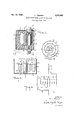
- FIG. 1 shows a cross-section of a high precision resistor constructed in accordance with this invention
- FIG. 2 is a schematic representation of the resistor of FIG. 1 at an intermediate stage of manufacture
- FIG. 3 is a plan view of the resistor of FIG. 2;
- FIG. 4 is a schematic representation of the electrical connections and measuring points of the resistor of FIG. 2.
- the resistor in FIG. 1 is enclosed within hollow container 1, preferably of synthetic resin, which is open at one end.
- a plurality of resistors 2, only one of which appears in the drawing, is located within the container 1 and physically positioned parallel to each other pointing, respectively, at the closed end 3 and the open end 4 of the container 1.
- the resistors 2 may comprise any suitable form of resistor, such as an insulating body coated with a conductive layer of metal or other material.
- the resistors are connected as shown in FIG. 2 so as to be electrically in series, with alternate junctions between resistors adjacent the closed end 3 and the open end 4 of the container.
- An opening 6 is provided in the closed end 3 of the container and a conductive metal bushing 7 having a locking flange 8 is placed in the opening to fill it up and serve as a closure therefor.
- the bushing is internally threaded, as indicated by reference number 9, and has a cylindrical appendage 10 extending into the container.
- the external surface of the appendage 10 is knurled or otherwise roughened to receive and to hold fast to one end of a tube 11 or insulating material.
- One terminal or lead 12 at one end of the series-connected resistors 2 is wound around and conductively joined to the appendage 10.
- a machine screw 13 together with a washer 14 may be used as an external fastening means to make electrical connection to the outside of the composite resistor in order to connect with the terminal 12 within the container 1.
- the tube 11 serves to dam off a region within the container 1 when the latter is placed in the position shown in FIG. 2 and is partially filled with an encapsulating material 5 in liquid form.
- a compensating resistor 15 is chosen and placed within the dammed-off region and is connected by means of a lead 16 to the opposite end of the series-connected resistors from the lead 12. The selection of resistor 15 will be described in greater detail hereinafter.
- the container 1 is thereafter filled with the encapsulating material which is allowed to set. Subsequently, a hole 17 is formed in the surface of the material 5 and a hollow bushing 18 having an extension 19 is forced into the hole 17.
- this bushing is coaxial with the bushing 7 at the other end of the container 1.
- the bushing 18 has a locking collar 20 to prevent it from turning and to increase the friction on the surface of the encapsulating material 5 and the outer end of the bushing is threaded, as indicated by reference numeral 21.
- this thread matches the internal thread of the bushing 7 so that similar composite resistors can be joined end to end, as indicated by the container 1 and the container 1a.
- the bushing 18 has an axial hole 22 through which extends a lead 23 from the compensating resistor 15. The protruding end of the lead may be cut off and welded to the bushing, as indicated by reference character 24, so as to seal ofi the assembly.
- the resistors 2 are chosen so that when connected in series their total ohmic value will be slightly less than the desired value. After the resistors have been introduced into the container 1 and after connection has been made between the lead 12 and the appendage 10 and the tube 11 has been attached to the appendage 10, the container 1 is placed in the position as shown in FIG. 2 and filled to the level 25 which, it will be noted, is lower than the open end of the tube 11. Therefore, the latter serves as a dam and prevents the encapsulating material, which may be an epoxy resin, for example, from spilling over into the region within the tube 11.
- the encapsulating material which may be an epoxy resin, for example, from spilling over into the region within the tube 11.
- the level 25 is such as to immerse completely the resistive element portion of each of the resistors 2, leaving only the conductive terminals 26 between resistors above the level of the encapsulating material.
- a measurement may then be made of the total resistance between the lead 12 and the lead 16 at the ends of the series-connected resistors.
- the compensating resistor 15 is then selected to have a value equal to the difference between the desired value of the composite resistor and the total value of the resistors 2. If a composite resistor of high ohmic value is to be made, it may be necessary to measure the resistance of one pair of resistors 2 at a time. Such measurements may be made at the points indicated by the reference letters A, B, C and D, as shown in FIG. 4, and it is for this reason that it is desirable to have the terminals 26 remain above the level 25 of the encapsulating material 5.
- the compensating resistor 15 After the compensating resistor 15 has been selected, one of its leads is connected to the lead 16 of the resistors 2 and the compensating resistor is placed within the tube 11. Thereafter, more encapsulating material is added to bring the level up to the open end 4 of the container 1. In so doing, encapsulating material spills over inside the tube 11 and encases the compensating resistor 15. This changes the value of resistance of the compensating resistor, but since the total resistance of the compensating resistor is only a small fraction of the total resistance of the composite resistor, any change in its value is relatively negligible.
- c the change in resistance of the composite resistor
- a the fraction of total resistance of the composite resistor represented by the compensating resistor
- b is the change in resistance of the compensating resistor.
- a precision composite resistor comprising: a plurality of individual resistors connected together into a twoterminal network; a container enclosing said resistors, said container having an interior wall separating one portion of said container from the remainder, said resistors being located within said remainder; conductive terminal means extending through the bottom of said container, one terminal of said two-terminal network being connected to said terminal means within said container; a compensating resistor connected to said two-terminal network and located within said one portion; encapsulating material substantially filling said container and covering said individual resistors and said compensating resistor; and second terminal means located in the surface of said encapsulating material and connected to said compensating resistor.
- a precision composite resistor comprising: a plurality of individual resistors connected together into a two-terminal network; a container enclosing said resistors, said container having an interior wall extending from the bottom of the container and separating one portion of the container from the remainder, said resistors being located within said remainder and extending substantially perpendicularly to the bottom of said container; conductive terminal means extending through the bottom of said container, one terminal of said two-terminal network being connected to said terminal means within said container; a compensating resistor connected to said twoterminal network and located within said one portion; encapsulating material substantially filling said container and covering said individual resistors and said compensating resistor; and second terminal means located in the surface of said encapsulating material and connected to said compensating resistor.
- a precision composite resistor comprising: a plurality of individual resistors connected together into a twoterminal network; a container enclosing said resistors, said container having an interior wall separating one portion of said container from the remainder, said resistors being located within said remainder and being physically arranged to extend substantially perpendicularly to the bottom of said container, said interior wall extending at least substantially as far from the bottom of said container as said resistors; conductive terminal means extending through the bottom of said container, one terminal of said two-terminal network being connected to said terminal means within said container; a compensating resistor connected to said two-terminal network and located within said one portion; encapsulating material substantially filling said container and covering said individual resistors and said compensating resistor; and second terminal means located in the surface of said encapsulating material and connected to said compensating resistor.
Landscapes
- Engineering & Computer Science (AREA)
- Manufacturing & Machinery (AREA)
- Microelectronics & Electronic Packaging (AREA)
- Apparatuses And Processes For Manufacturing Resistors (AREA)
Description
Oct. 19, 1965 TAS SARA 3,213,402
ENCAPSULATED HIGH PRECISION RESISTOR Filed March 28. 1961 INVENTOR. Lu/G/ mas/4 :4
United States Patent "ice 3,213,402 ENCAPSULATED HIGH PRECISION RESISTOR Luigi Tassara, Via Olmetto 3, Milan, Italy Filed Mar. 28, 1961, Ser. No. 98,861 3 Claims. (Cl. 338-260) The present invention relates to encapsulated resistors of high precision, for example of the order of .l%, and to a method for making the same and retaining the high precision in spite of the change in resistance produced by the encapsulation process. The invention is particularly adaptable to resistors of high ohmic value.
A resistor constructed according to the invention comprises a plurality of individual resistors not previously encapsulated connected together end to end and arranged so as to be physically parallel to each other within a container. The location of the resistors within the container is such that one end of each of the resistors points in the same direction toward the open mouth of the container to extend above the surface of encapsulating material poured into the container. Also located within the container is a region dammed off from the remainder and of sufficient size to receive an additional resistor. The ohmic value of the series-connected resistors is predetermined to be slightly less than the desired ohmic value of the finished resistor, and after the encapsulating material has been poured around the series-connected resistors and allowed to set, the resultant resistance is measured and an additional resistor sufficient to bring the total series resistance up to the desired value is connected to the other resistors and is inserted into the dammed-off section. Thereafter, this section is also filled with encapsulating material and additional encapsulating material is added to cover the open ends of all of the resistors.
The composite resistor may be formed so as to be easily connected in series in similar composite resistors by providing a terminal at each end thereof, one of the terminals comprising an internally threaded nut and the other terminal comprising an externally threaded bolt.
The invention will be further described in connection with the drawings, in which:
FIG. 1 shows a cross-section of a high precision resistor constructed in accordance with this invention;
FIG. 2 is a schematic representation of the resistor of FIG. 1 at an intermediate stage of manufacture;
FIG. 3 is a plan view of the resistor of FIG. 2; and
FIG. 4 is a schematic representation of the electrical connections and measuring points of the resistor of FIG. 2.
The resistor in FIG. 1 is enclosed within hollow container 1, preferably of synthetic resin, which is open at one end. A plurality of resistors 2, only one of which appears in the drawing, is located within the container 1 and physically positioned parallel to each other pointing, respectively, at the closed end 3 and the open end 4 of the container 1. The resistors 2 may comprise any suitable form of resistor, such as an insulating body coated with a conductive layer of metal or other material. The resistors are connected as shown in FIG. 2 so as to be electrically in series, with alternate junctions between resistors adjacent the closed end 3 and the open end 4 of the container.
An opening 6 is provided in the closed end 3 of the container and a conductive metal bushing 7 having a locking flange 8 is placed in the opening to fill it up and serve as a closure therefor. The bushing is internally threaded, as indicated by reference number 9, and has a cylindrical appendage 10 extending into the container. The external surface of the appendage 10 is knurled or otherwise roughened to receive and to hold fast to one end of a tube 11 or insulating material. One terminal or lead 12 at one end of the series-connected resistors 2 is wound around and conductively joined to the appendage 10. A machine screw 13 together with a washer 14 may be used as an external fastening means to make electrical connection to the outside of the composite resistor in order to connect with the terminal 12 within the container 1.
The tube 11 serves to dam off a region within the container 1 when the latter is placed in the position shown in FIG. 2 and is partially filled with an encapsulating material 5 in liquid form. A compensating resistor 15 is chosen and placed within the dammed-off region and is connected by means of a lead 16 to the opposite end of the series-connected resistors from the lead 12. The selection of resistor 15 will be described in greater detail hereinafter.
The container 1 is thereafter filled with the encapsulating material which is allowed to set. Subsequently, a hole 17 is formed in the surface of the material 5 and a hollow bushing 18 having an extension 19 is forced into the hole 17. Preferably, this bushing is coaxial with the bushing 7 at the other end of the container 1. The bushing 18 has a locking collar 20 to prevent it from turning and to increase the friction on the surface of the encapsulating material 5 and the outer end of the bushing is threaded, as indicated by reference numeral 21. Preferably, this thread matches the internal thread of the bushing 7 so that similar composite resistors can be joined end to end, as indicated by the container 1 and the container 1a. The bushing 18 has an axial hole 22 through which extends a lead 23 from the compensating resistor 15. The protruding end of the lead may be cut off and welded to the bushing, as indicated by reference character 24, so as to seal ofi the assembly.
The process of forming the composite resistor just described will now be considered in greater detail. Refer ence has already been made to the fact that alternate connections between the resistors 2 are adjacent the closed end 3 and the open end 4 of the container 1. If the resistors are very numerous, they may be arranged in a spiral, as indicated in FIG. 3.
The resistors 2 are chosen so that when connected in series their total ohmic value will be slightly less than the desired value. After the resistors have been introduced into the container 1 and after connection has been made between the lead 12 and the appendage 10 and the tube 11 has been attached to the appendage 10, the container 1 is placed in the position as shown in FIG. 2 and filled to the level 25 which, it will be noted, is lower than the open end of the tube 11. Therefore, the latter serves as a dam and prevents the encapsulating material, which may be an epoxy resin, for example, from spilling over into the region within the tube 11. The level 25 is such as to immerse completely the resistive element portion of each of the resistors 2, leaving only the conductive terminals 26 between resistors above the level of the encapsulating material. A measurement may then be made of the total resistance between the lead 12 and the lead 16 at the ends of the series-connected resistors. The compensating resistor 15 is then selected to have a value equal to the difference between the desired value of the composite resistor and the total value of the resistors 2. If a composite resistor of high ohmic value is to be made, it may be necessary to measure the resistance of one pair of resistors 2 at a time. Such measurements may be made at the points indicated by the reference letters A, B, C and D, as shown in FIG. 4, and it is for this reason that it is desirable to have the terminals 26 remain above the level 25 of the encapsulating material 5.
While each of the resistors 2 could be measured to any desired accuracy before being encapsulated, the proc Patented Oct. 19, 1965 ess of encapsulation produces a change in the resistance, and this change cannot be predicted precisely. The change may not be large, for example it may only be approximately 1%. However, if it is desired to produce a composite resistor to an accuracy of .1%, clearly a change of 1% would be intolerable, particularly where the change would vary from one composite resistor to the next.
After the compensating resistor 15 has been selected, one of its leads is connected to the lead 16 of the resistors 2 and the compensating resistor is placed within the tube 11. Thereafter, more encapsulating material is added to bring the level up to the open end 4 of the container 1. In so doing, encapsulating material spills over inside the tube 11 and encases the compensating resistor 15. This changes the value of resistance of the compensating resistor, but since the total resistance of the compensating resistor is only a small fraction of the total resistance of the composite resistor, any change in its value is relatively negligible. The change in value of the resistance of the composite resistor due to a change in value of the resistance of the compensating resistor is given by the equation a b=c, where c is the change in resistance of the composite resistor, a is the fraction of total resistance of the composite resistor represented by the compensating resistor and b is the change in resistance of the compensating resistor. To be specific, if the change in value of the composite resistor given by the letter c must be less than .1% and if the change in resistance of the compensating resistor is known to be not greater than 2% when it is encapsulated, then the compensating resistor must have a resistance no greater than 5% of the total value of the composite resistor.
Although this invention has been described in terms of a specific embodiment, it will be understood that modifications may be made therein without departing from the scope of the invention as measured by the following claims.
I claim:
1. A precision composite resistor comprising: a plurality of individual resistors connected together into a twoterminal network; a container enclosing said resistors, said container having an interior wall separating one portion of said container from the remainder, said resistors being located within said remainder; conductive terminal means extending through the bottom of said container, one terminal of said two-terminal network being connected to said terminal means within said container; a compensating resistor connected to said two-terminal network and located within said one portion; encapsulating material substantially filling said container and covering said individual resistors and said compensating resistor; and second terminal means located in the surface of said encapsulating material and connected to said compensating resistor.
2. A precision composite resistor comprising: a plurality of individual resistors connected together into a two-terminal network; a container enclosing said resistors, said container having an interior wall extending from the bottom of the container and separating one portion of the container from the remainder, said resistors being located within said remainder and extending substantially perpendicularly to the bottom of said container; conductive terminal means extending through the bottom of said container, one terminal of said two-terminal network being connected to said terminal means within said container; a compensating resistor connected to said twoterminal network and located within said one portion; encapsulating material substantially filling said container and covering said individual resistors and said compensating resistor; and second terminal means located in the surface of said encapsulating material and connected to said compensating resistor.
3. A precision composite resistor comprising: a plurality of individual resistors connected together into a twoterminal network; a container enclosing said resistors, said container having an interior wall separating one portion of said container from the remainder, said resistors being located within said remainder and being physically arranged to extend substantially perpendicularly to the bottom of said container, said interior wall extending at least substantially as far from the bottom of said container as said resistors; conductive terminal means extending through the bottom of said container, one terminal of said two-terminal network being connected to said terminal means within said container; a compensating resistor connected to said two-terminal network and located within said one portion; encapsulating material substantially filling said container and covering said individual resistors and said compensating resistor; and second terminal means located in the surface of said encapsulating material and connected to said compensating resistor.
References Cited by the Examiner v UNITED STATES PATENTS 563,780 7/96 Minchew 338-319 872,208 11/07 Wiegand 3 38-319 1,047,742 12/ 12 Buchanan 338-319 1,104,841 7/14 Smith 338-77 1,526,843 2/25 Dominguez 338-319 2,547,405 4/51 Mitchell et al. 338-235 2,933,804 4/60 Math 29-155.63 3,051,922 8/62 Julie 338-235 3,064,335 1 1/ 62 Fletcher 29-155 .63
RICHARD M. WOOD, Primary Examiner.
RAY K. WINDHAM, Examiner.
Claims (1)
1. A PRECISION COMPOSITE RESISTOR COMPRISING: A PLURALITY OF IONDIVIDUAL RESISTORS CONNECTED TOGETHER INTO A TWOTERMINAL NETWORK; A CONTAINER ENCLOSIONG SAID RESISTORS, SAID CONTAINER HAVING AN INTERIOR WALL SEPARATING ONE PORTION OF SAID CONTAINER FROM THE REMAINDER, SAID RESISTORS BEING LOCATED WITHIN SAID REMAINDER; CONDUCTIVE TERMINAL MEANS EXTENDING THROUGH THE BOTTOM OF SAID CONTAINER, ONE TERMINAL OF SAID TWO-TERMINAL NETWORK BEING CONNECTED TO SAID TERMINAL MEANS WITHIN SAID CONTAINER; A COMPENSATING RESISTOR CONNECTED TO DAIS TWO-TERMINAL NETWORK AND LOCATED WITHIN SAID ONE PORTION; ENCAPSULATING MATERIAL SUBSTANTIALLY FILLING SAAID CONTAINER AND COVERING SAID INDIV IDUAL RESISTORS AND SAID COMPENSATION RESISTOR; AND SECOND TERMINAL MEANS LOCATED IN THE SURFACE OF SAID ENCAPSULATING MATERIAL AND CONNECTED TO SAID COMPENSATING RESISTOR.
Priority Applications (2)
| Application Number | Priority Date | Filing Date | Title |
|---|---|---|---|
| US98861A US3213402A (en) | 1961-03-28 | 1961-03-28 | Encapsulated high precision resistor |
| US429693A US3348304A (en) | 1961-03-28 | 1964-12-09 | Method of making encapsulated resistors of high precision |
Applications Claiming Priority (1)
| Application Number | Priority Date | Filing Date | Title |
|---|---|---|---|
| US98861A US3213402A (en) | 1961-03-28 | 1961-03-28 | Encapsulated high precision resistor |
Publications (1)
| Publication Number | Publication Date |
|---|---|
| US3213402A true US3213402A (en) | 1965-10-19 |
Family
ID=22271295
Family Applications (1)
| Application Number | Title | Priority Date | Filing Date |
|---|---|---|---|
| US98861A Expired - Lifetime US3213402A (en) | 1961-03-28 | 1961-03-28 | Encapsulated high precision resistor |
Country Status (1)
| Country | Link |
|---|---|
| US (1) | US3213402A (en) |
Cited By (9)
| Publication number | Priority date | Publication date | Assignee | Title |
|---|---|---|---|---|
| US3441895A (en) * | 1967-03-08 | 1969-04-29 | Admiral Corp | Cermet resistance module |
| US3518603A (en) * | 1969-05-29 | 1970-06-30 | Philco Ford Corp | Resistive voltage divider |
| US3737831A (en) * | 1965-03-12 | 1973-06-05 | Ite Imperial Corp | Resistor assembly with compression plate supports |
| US3813631A (en) * | 1972-08-09 | 1974-05-28 | Hitachi Ltd | High resistance resistor device for dc high voltage circuits |
| JPS5029253U (en) * | 1973-07-12 | 1975-04-03 | ||
| US3900819A (en) * | 1973-02-07 | 1975-08-19 | Environmental Instruments | Thermal directional fluid flow transducer |
| US4418474A (en) * | 1980-01-21 | 1983-12-06 | Barnett William P | Precision resistor fabrication employing tapped resistive elements |
| US5977862A (en) * | 1996-04-26 | 1999-11-02 | Gec Alsthom T & D Sa | Polymer high voltage current limiters packaged in series |
| US20130335887A1 (en) * | 2012-06-13 | 2013-12-19 | Hitachi, Ltd. | Resistor, method of assembling the same, and switchgear |
Citations (9)
| Publication number | Priority date | Publication date | Assignee | Title |
|---|---|---|---|---|
| US563780A (en) * | 1896-07-14 | Charles henry minciiew | ||
| US872208A (en) * | 1905-10-30 | 1907-11-26 | Cutler Hammer Mfg Co | Inclosed resistance. |
| US1047742A (en) * | 1912-03-18 | 1912-12-17 | Frank Buchanan | Electrical resistance. |
| US1104841A (en) * | 1913-03-12 | 1914-07-28 | Leeds & Northrup Co | Resistance set. |
| US1526843A (en) * | 1923-11-22 | 1925-02-17 | Charles A Denis | Electric heating element |
| US2547405A (en) * | 1945-06-07 | 1951-04-03 | Shallcross Mfg Company | Hermetically sealed resistor |
| US2933804A (en) * | 1955-05-12 | 1960-04-26 | Math Fritz | Electrical wire resistors and method of manufacturing the same |
| US3051922A (en) * | 1957-03-29 | 1962-08-28 | Julie Res Lab Inc | Precision resistance apparatus and method of making |
| US3064335A (en) * | 1959-02-24 | 1962-11-20 | Carrier Corp | Method of manufacturing variable resistors |
-
1961
- 1961-03-28 US US98861A patent/US3213402A/en not_active Expired - Lifetime
Patent Citations (9)
| Publication number | Priority date | Publication date | Assignee | Title |
|---|---|---|---|---|
| US563780A (en) * | 1896-07-14 | Charles henry minciiew | ||
| US872208A (en) * | 1905-10-30 | 1907-11-26 | Cutler Hammer Mfg Co | Inclosed resistance. |
| US1047742A (en) * | 1912-03-18 | 1912-12-17 | Frank Buchanan | Electrical resistance. |
| US1104841A (en) * | 1913-03-12 | 1914-07-28 | Leeds & Northrup Co | Resistance set. |
| US1526843A (en) * | 1923-11-22 | 1925-02-17 | Charles A Denis | Electric heating element |
| US2547405A (en) * | 1945-06-07 | 1951-04-03 | Shallcross Mfg Company | Hermetically sealed resistor |
| US2933804A (en) * | 1955-05-12 | 1960-04-26 | Math Fritz | Electrical wire resistors and method of manufacturing the same |
| US3051922A (en) * | 1957-03-29 | 1962-08-28 | Julie Res Lab Inc | Precision resistance apparatus and method of making |
| US3064335A (en) * | 1959-02-24 | 1962-11-20 | Carrier Corp | Method of manufacturing variable resistors |
Cited By (10)
| Publication number | Priority date | Publication date | Assignee | Title |
|---|---|---|---|---|
| US3737831A (en) * | 1965-03-12 | 1973-06-05 | Ite Imperial Corp | Resistor assembly with compression plate supports |
| US3441895A (en) * | 1967-03-08 | 1969-04-29 | Admiral Corp | Cermet resistance module |
| US3518603A (en) * | 1969-05-29 | 1970-06-30 | Philco Ford Corp | Resistive voltage divider |
| US3813631A (en) * | 1972-08-09 | 1974-05-28 | Hitachi Ltd | High resistance resistor device for dc high voltage circuits |
| US3900819A (en) * | 1973-02-07 | 1975-08-19 | Environmental Instruments | Thermal directional fluid flow transducer |
| JPS5029253U (en) * | 1973-07-12 | 1975-04-03 | ||
| US4418474A (en) * | 1980-01-21 | 1983-12-06 | Barnett William P | Precision resistor fabrication employing tapped resistive elements |
| US5977862A (en) * | 1996-04-26 | 1999-11-02 | Gec Alsthom T & D Sa | Polymer high voltage current limiters packaged in series |
| US20130335887A1 (en) * | 2012-06-13 | 2013-12-19 | Hitachi, Ltd. | Resistor, method of assembling the same, and switchgear |
| US9312669B2 (en) * | 2012-06-13 | 2016-04-12 | Hitachi, Ltd. | Resistor, method of assembling the same, and switchgear |
Similar Documents
| Publication | Publication Date | Title |
|---|---|---|
| US3213402A (en) | Encapsulated high precision resistor | |
| US2958844A (en) | High voltage, high altitude bushing | |
| US1931043A (en) | Electrical impedance device | |
| US3388211A (en) | Sealing bushing and wall member for electrical apparatus and method of assembling same | |
| US2720617A (en) | Transistor packages | |
| US3962667A (en) | Combination fuse and bushing | |
| US3348304A (en) | Method of making encapsulated resistors of high precision | |
| US2640132A (en) | Electrical resistor and method of making same | |
| US3239595A (en) | Seal arrangement for electrical devices | |
| US2063642A (en) | Electric heating unit | |
| US2875419A (en) | Tunable radio frequency coils | |
| US3699200A (en) | High-resistance electrical conductor encapsulation | |
| US3394259A (en) | Hollow conically shaped infrared reference source formed from bare and insulated helically wound wires | |
| US2735301A (en) | Schwob | |
| US2783341A (en) | Probe for liquid level indicator | |
| US2466211A (en) | High-voltage resistor | |
| US3101466A (en) | Wound resistor | |
| US2793526A (en) | Humidity measuring device | |
| US4327245A (en) | Sealing end for direct current electric cables | |
| US2846536A (en) | Electric heaters | |
| GB1055751A (en) | Solid electrolytic capacitors | |
| US2735922A (en) | johnson | |
| US3334322A (en) | Resistance thermometer and method of making the same | |
| US3136972A (en) | Encapsulated resistor | |
| US2851574A (en) | Thermocouple reference junction |